I like Carbide Create for it’s fast and mostly intuitive usage. Kudo’s for making the program and continuing to support it. I have some requests that would help me out in the projects that I am doing:
For what I do I need to create text that is vertically flipped and or horizontally flipped. Currently all that is available is rotate and scale for the font effects. I tried to use a negative height hoping it would flip the text vertically but the input field will not accept “-”.
It would be helpful if the mouse pointer could show a little x, y coordinate from the top-left edge in mm or inches as I move it. I know it’s not totally necessary since you can put an object on the work area, double click it and then see the X, Y and edit it. Just might save a little time here and there when doing a not so critical job.
An export GCode as true .gcode extension rather than .egc format would be nice.
For me the first one is the most important and probably easy to implement. Not sure how it was coded and I realize that not many people need such a thing. It’s just when you create a branding iron or something that transfers ink, you have to create it in reverse to transfer properly.
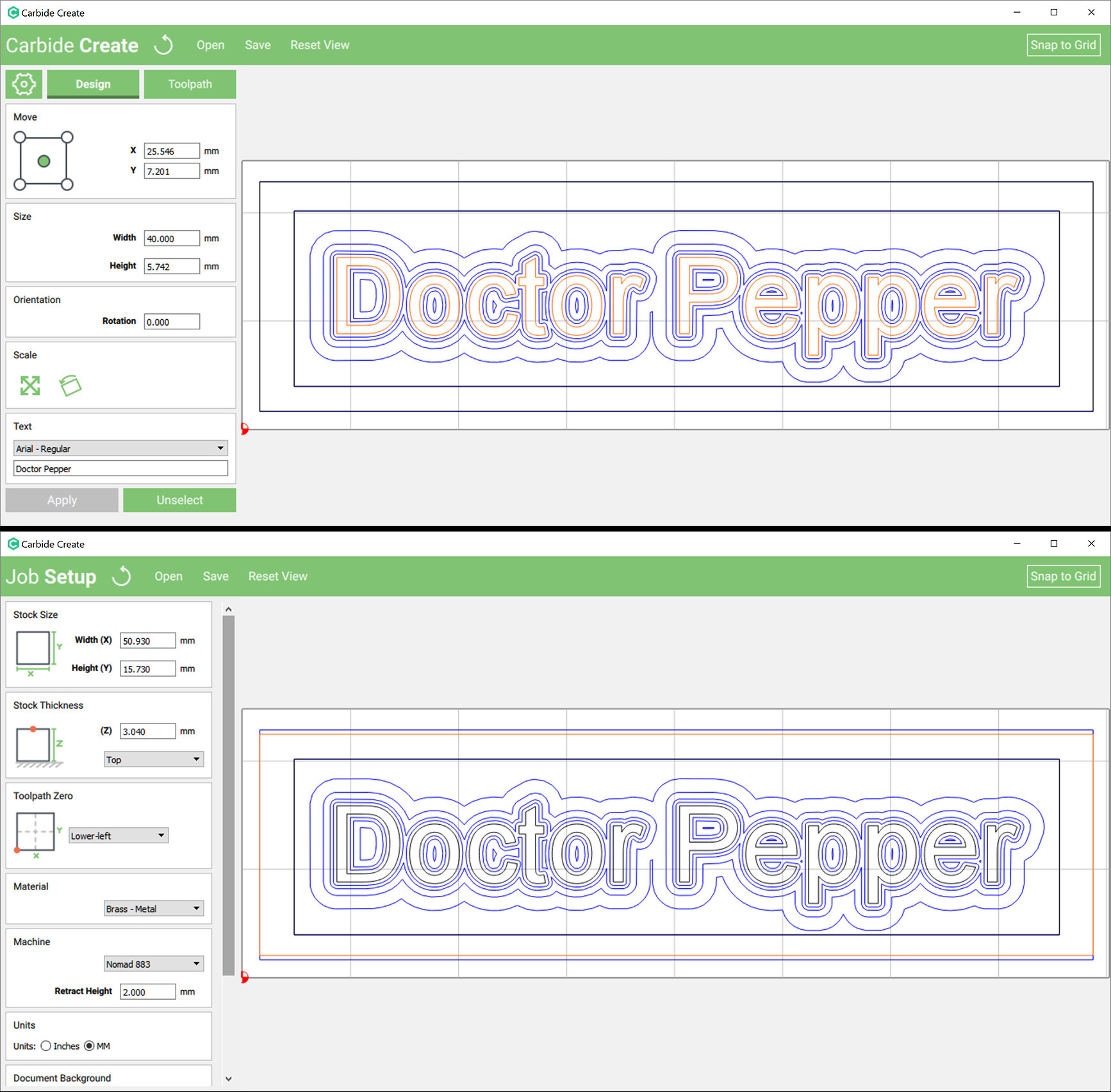
Thank you WillAdams for helping. I was hoping you could point me to where I could flip objects negatively or convert the text to paths within Carbide Create. I have attached a screen capture of the text portion I was using in my test.
Here is the text portion options along with the projects options (2nd image).
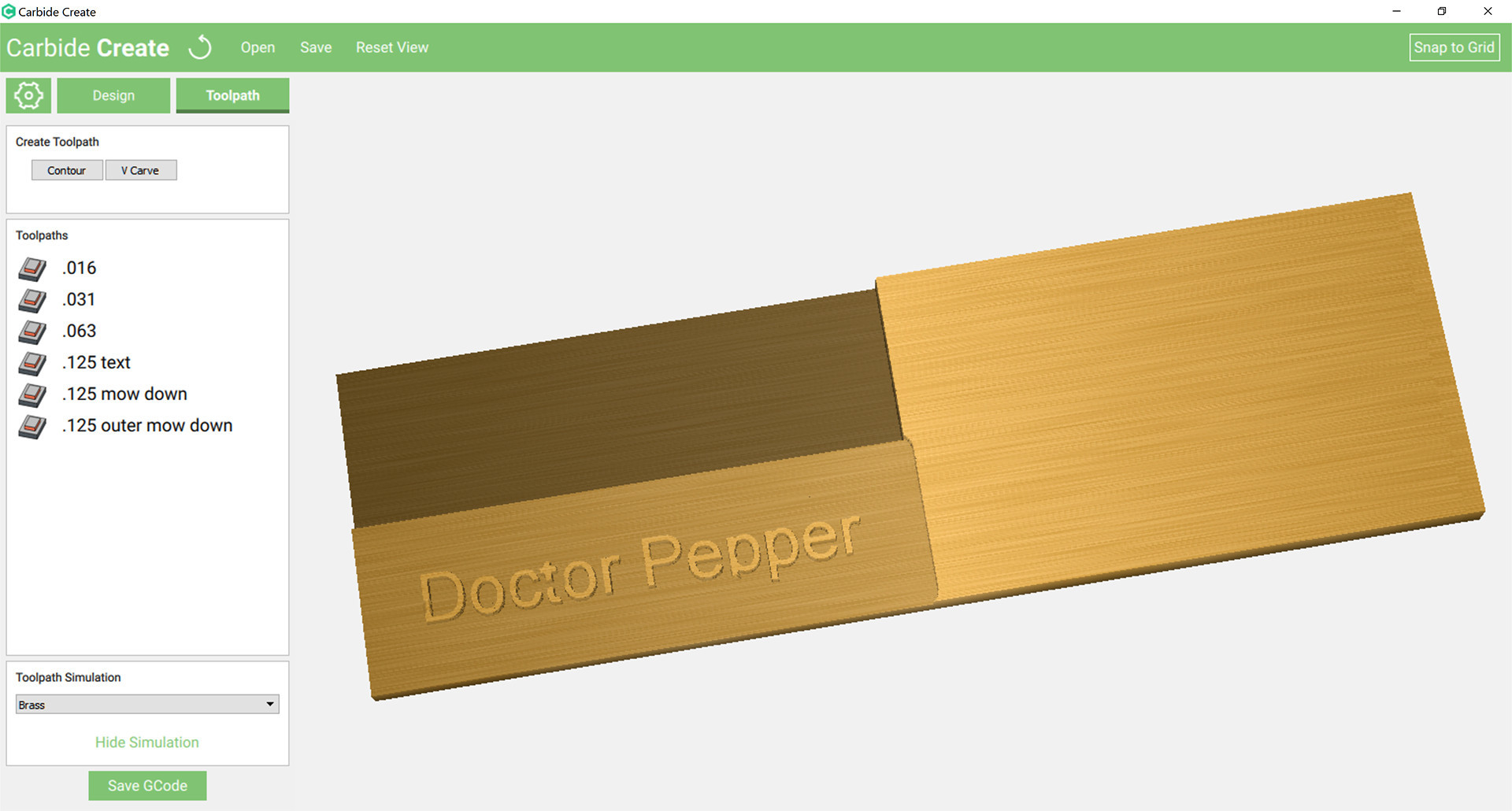
Oh, and here’s a bug in Carbide Create when doing the “Show Simulation”. It shows extra material to the top and right of the entire project. Plus, some of the letters are damaged such as part of the “p” in the double “pp” portion.
I have had similar problems with the simulation.
About point 2… As I understand they want Carbide Create to be only used by carbide 3D comunity (SO3, nomad) so generated code will only be understood by Carbide Motion. There was I way (I think) to extract pure Gcode from the file using CM (once connected to the machine…) but right now I cant find how.
My biggest request with Carbide Create are TABS!!!
Not sure how to explain my request, but I’ll try. If one of you can boil it down or use CNC terminology all the better.
I need to cut multiple holes of exact same settings multiple times out of the same sheet. 9 holes of 3/4" diameter.
In Carbide Create currently I have to select the first hole, set the tool, set the depth per pass, step over, feedrate, plungerate, max depth and offest direction.
I need to set these parameters for each hole even though they are the same (except for path name)
Is there something I’m missing, or could there be a setting that would capture and duplicate all these settings?
I agree @dorf_online! And while it is possible @WillAdams by selecting all paths and using one setting, it adds a lot of unnecessary movement (and time), because it moves around to each element for each change of depth, and it also makes it impossible to pull a single element out from that tool path if needed.
I was thinking that something along the lines of grouping/nesting could work well (and could also help clean up the UI a bit if groups were collapsible). Something similar to grouping layers in Photoshop. Basically you could create a series of paths, select the ones you want, and group them into a set. You could then apply the tool settings to the entire set. It would keep all of the paths separate, so you could delete/enable/disable/etc, but still only have to manage the tool settings in one place.
jfo, thank you for understanding my request and adding the part I missed about selecting them all under one tool path. You are correct, the ONLY reason I don’t do that is because of wasted time and movement.
Those are some good feature requests that I would like as well. Some other features that would be nice:
In the JOB SETUP mode:
Grid options:
As an option it would be nice if the X, Y Grid could auto size to the width, height that you pick for the project. As an example set the project to 103mm by 103mm and you will find the grid is not proportional. The problem with this is that the “Snap to Grid” is not usable at this point due to the grid not being symmetrical.
As an option be able to set the grid slices. ie. 3 slices per inch, 1 per 2mm, etc.
Remember the defaults. ie. I do NOT have a “Shapeoko 3”, like mm instead of inches, working with “acrylic-plastic” more times than not but CC always reverts back to the defaults.
In the DESIGN mode:
When working with point “edit mode”, it would be nice to see an X, Y for each POINT so you can match other points to the same X or Y. Instead you only see the X, Y for the entire blob of points.
When zoomed in, it would be nice to have scroll bars so you do not have to zoom out/reset view then zoom into another point. I find I waste a lot of time zooming in/out/in/out to try to get to a portion that is off the screen.
There is no way to simply draw a line (two points) as a cut. It disappears immediately.
In Photoshop you can press and hold the “Shift” key and drag a point up/down or left/right and it will keep the point steady. ie. if you move a point in the X direction, the Y will stay firm and not drift up/down. This would be nice in Carbide Create as I find I have to constantly zoom in just to see if a point is lined up with another point.
Copy an existing object and paste it down elsewhere. This way you do not need to enter all of the dimensions for a similar hole, box, etc. (Mentioned above by “dorf online”)
If I click the “bottom-right” point of a box in the “MOVE” section, it would be nice if it stayed there until I change it to another point such as the center. Perhaps I am not understanding the box mentality and am using this wrong.
In the TOOLPATH mode:
If you start out making changes to your depth, inner, etc, and then pick another drill bit tool, it resets depth, inner, etc. I waste a lot of time not realizing that everything was reset.
The “Tool” should default to the last set tool, speed, feedrate, etc. It is more safe to assume that the same tool and settings are to be used for the next hole, box, etc being drilled than defaulting back to the defaults.
Under the “Tool” the “Set speeds automatically” keeps getting turned back on with a speed of .0001. When I don’t catch this the simulation can go on over 10 hours if I let it. Even cancelling takes just as long as letting the process complete on its own.
“Max Depth” keeps getting set to values that are larger than the entire project. Not sure where they are coming from.
want to +1 this issue. I think a very simple solution would be an single on / off option in the toolpath window that allows you to group cuts by depth or by curve. That way you could cater to both. Default should be group cuts by curve, would eliminate so much extra motion. So in a single toolpath, finish the cut for curve 1 before moving on to curve 2 etc.
When can we expect software upgrades for Carbide Motion and Carbide Create? Where do you find the release noted for each update? Does anyone know what could be potentially in the next upgrades?
I think Tabs will be useful, but I am living without them. Never-the-less, it is time consuming to prepare for full cut through. I like the method suggested to me from Tony (if I remember correctly) which involves painter’s tape on the bottom of the workpiece and also the waste board there under. Then Supergluing the the assy together. Has worked well for me but I worry about milling through all that gunk.
How about putting the saved settings into a .xml file rather than in the registry. It would be nice to be able to change them without editing the registry. Also save the most recent directory or at least let us set the directory it goes to when you click the Open menu button.
+1 gcode export from program
+1 tabs
+1 stl import
also S03 option to have the spindle speeds that match the more common router speed settings. or at the very least have the feed rate change based on the spindle speed. currently does not seem to affect the feed rate when i change the spindle speed.