What is wrong with the latest Carbide Create update?! I design a simple rectangle for a profile cut with filleted corners, save the code for cut, then it cuts two filleted corners and two 90 degree corners on the rectangle. This is extremely frustrating as it’s now done this on two pieces of wood wasting a shit ton of money on material that I can’t afford to purchase again for a few weeks.
Is anyone else experiencing this? It’s also pausing on one corner of the four edges and burning the wood as well as randomly dipping in the profile after rounding a corner.
I too am having a carbide create issue. I’ve spent a good part of the day working on it.
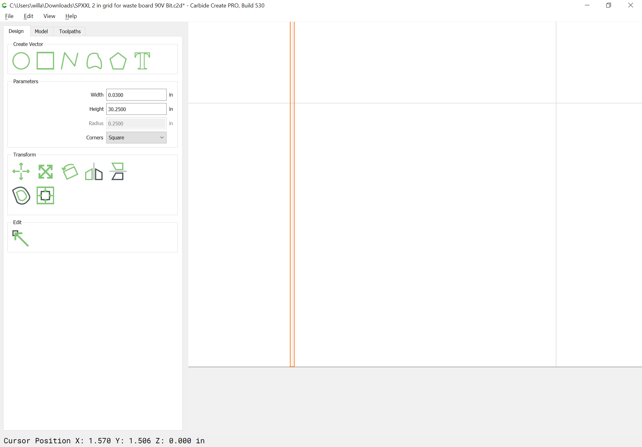
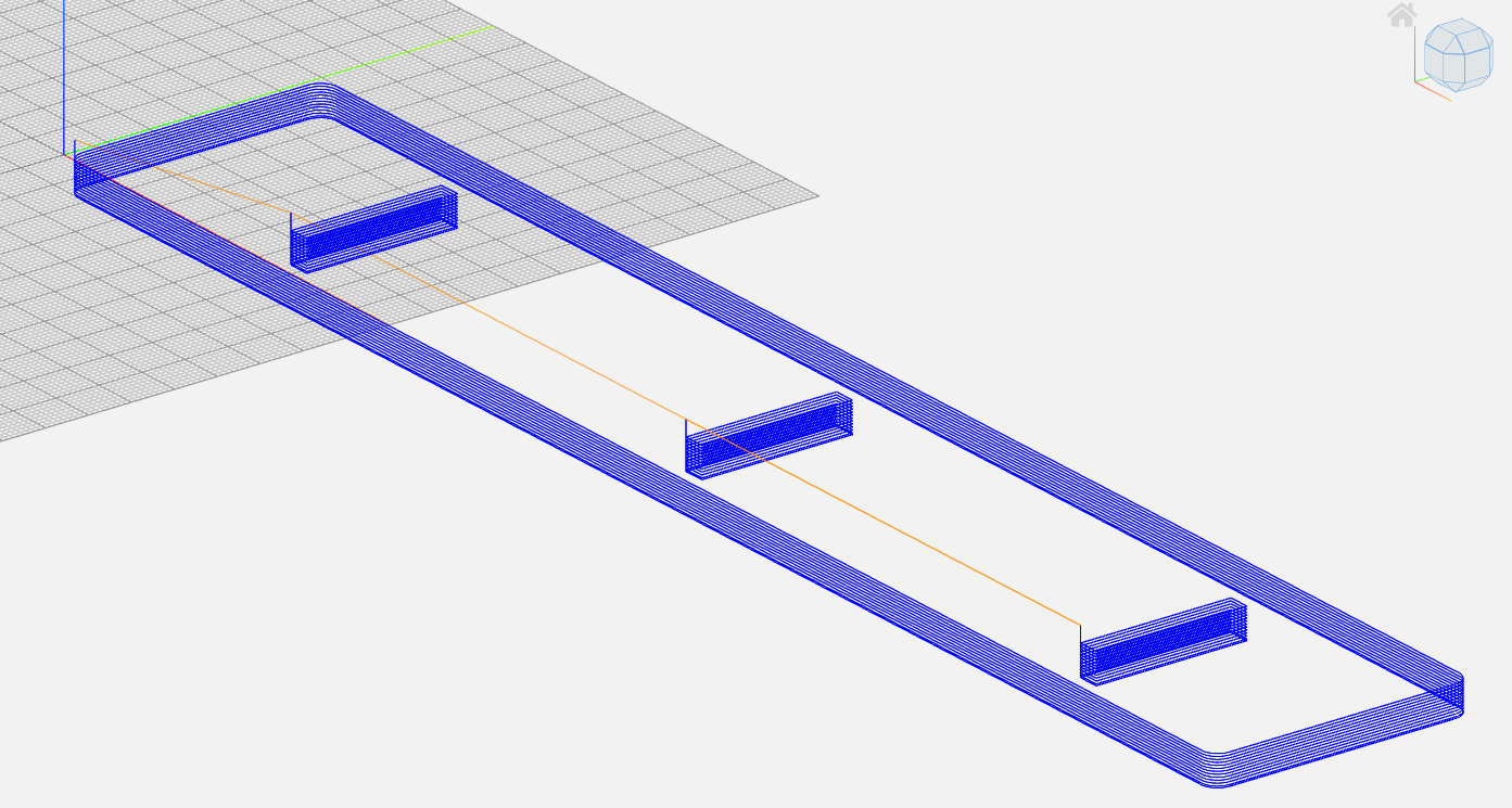
I am trying to create a (what I thought would be a simple file) 2 in. grid to cut onto my SPXXL waste board in CC.
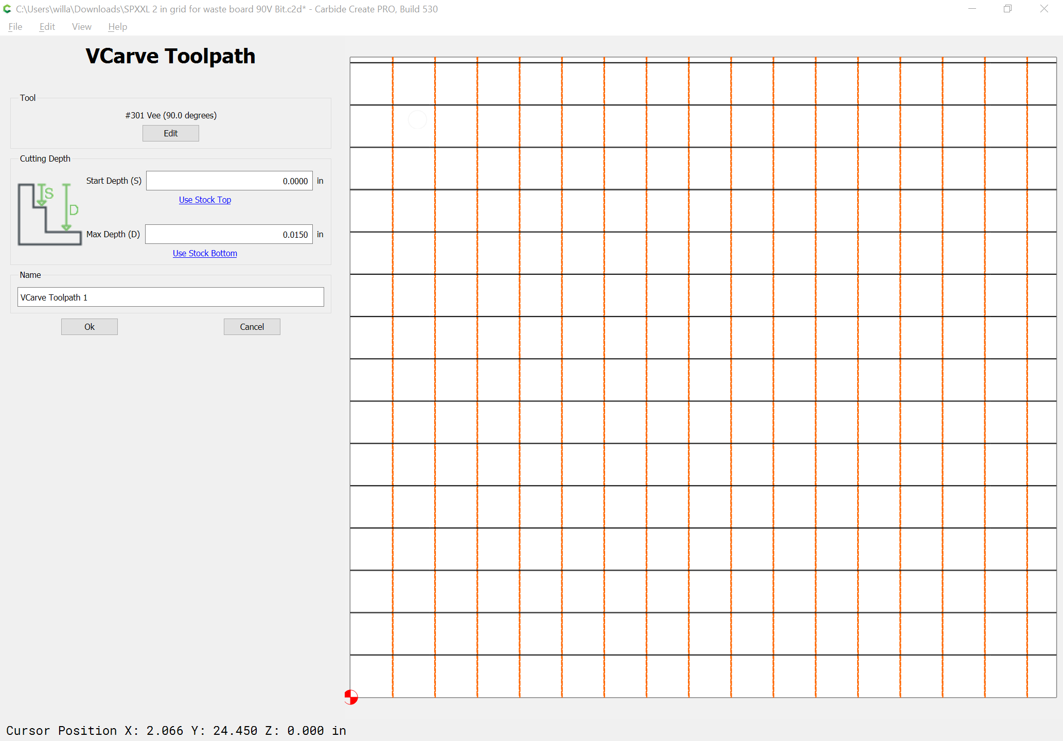
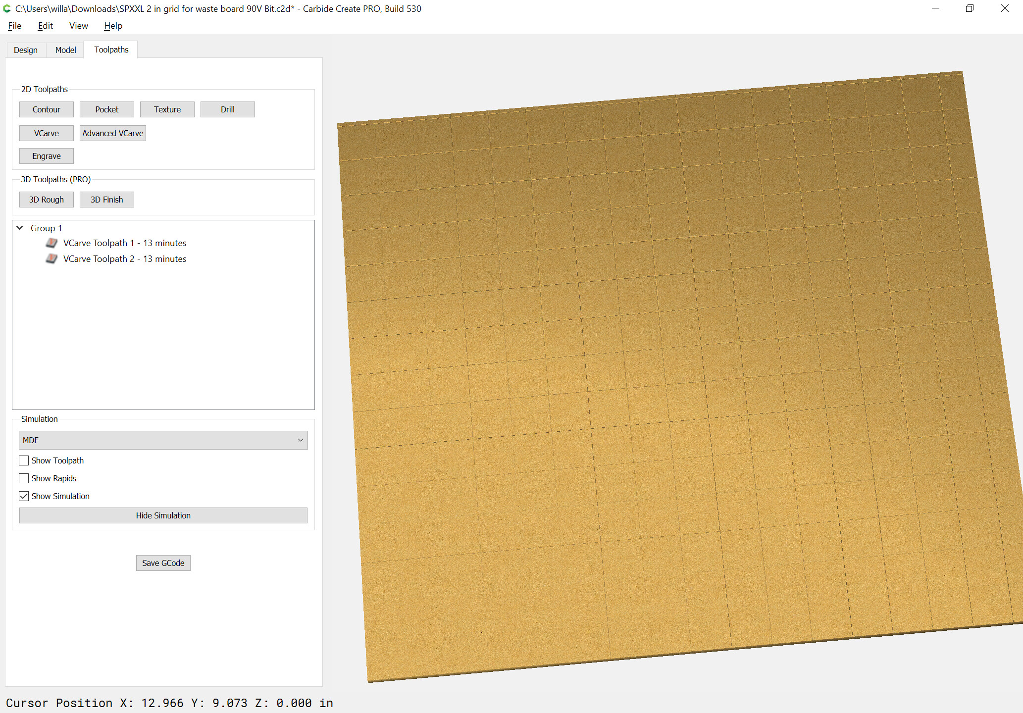
It does not show the tool path in the Simulation?
Attached is the file.
HMF… The one thing I didn’t try.
Oh… Very skinny rectangles.
I assume you made one then copied it and placed them on the line?
Can CC rotate the rectangle or did you have to create the perpendicular rectangle as well?
Wow, I am learning a lot here lately. I try to figure it out myself when possible.
Tomorrow I’ll be surfacing and gridding my waste board.
Cross your fingers and toes.
If so inclined pray for me as well.
I’ll need all the help I can get.
Sorry dude, I kind of stepped into your question and got in the way.
Everyone here is very helpful. I am sure they will be able to help.
I try to help when I can.
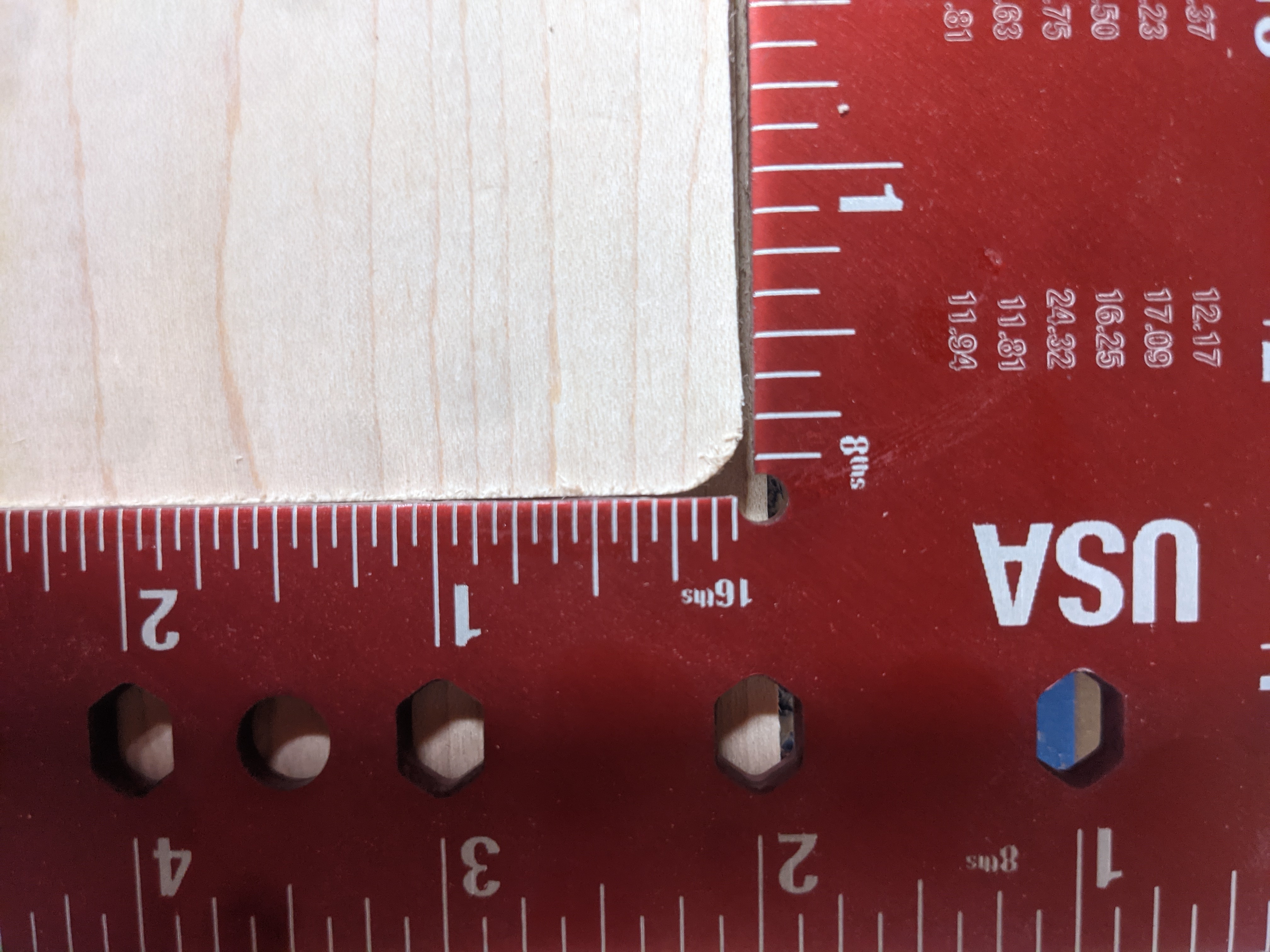
How are you setting your X and Y zero? It looks as if the bit never touched that horizontal path in the first picture. Is it possible your work piece shifted in one direction after your zeros were set or you never got a good zero on the corner?
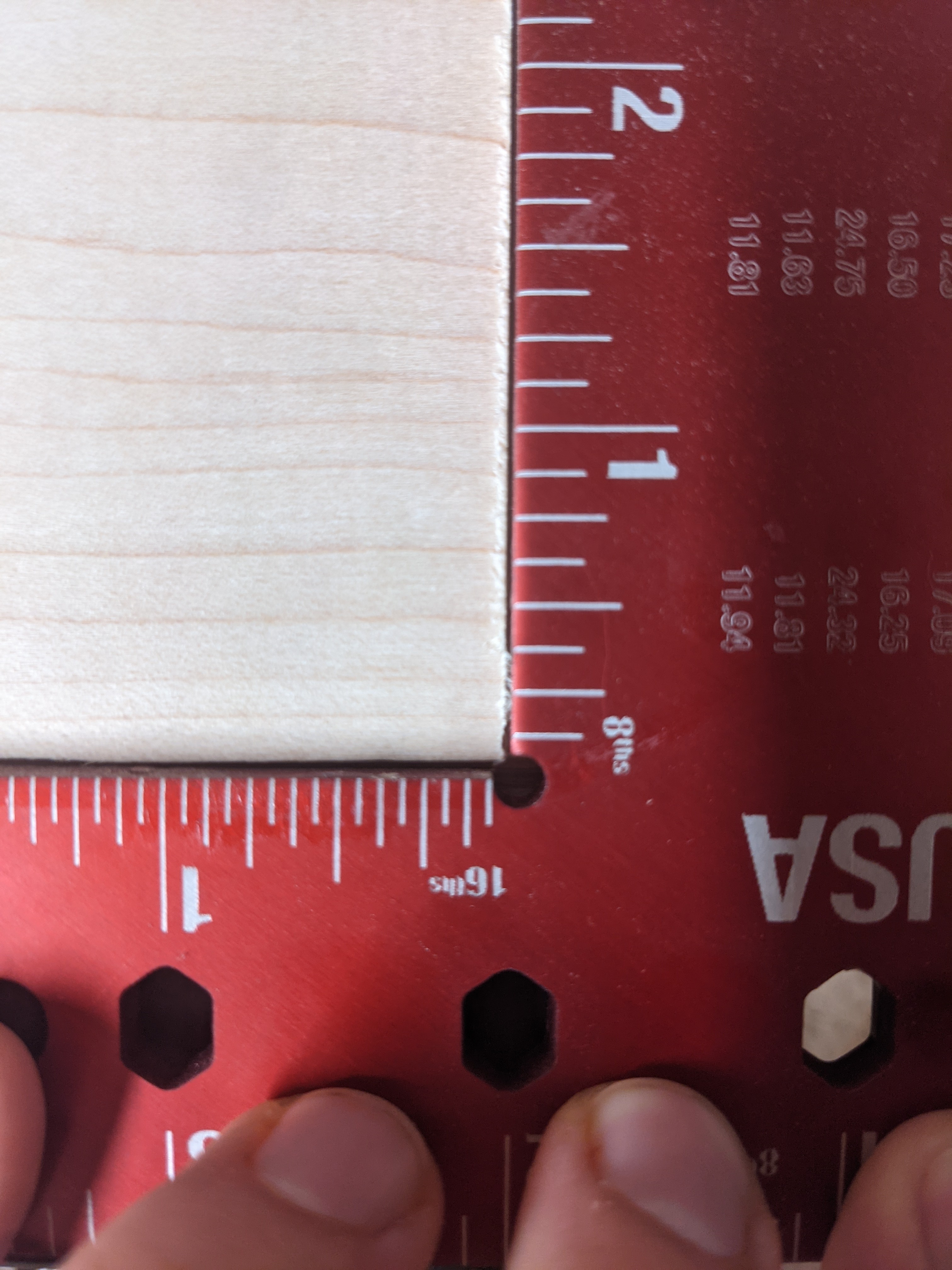
Now if you look at the picture with the straight corner (that should have been round), it seems like the right edge was machined (part circled in green) but the bottom edge may have been left untouched ? (part circled in orange):
If this is the case, this could explain the two missing rounded corners (I suppose that the other missing corner is at the left of the one in that pic ?)
If your stock was a little smaller than you think (or programmed), or if the X or Y reference shifted for some reason, the endmill may have cut air on one side, in which case it will have cut those two corners in the air, outside the stock.
Does this sound like a likely scenario considering the setup you used ?
If you have MDF scraps you could try and rerun this job, making sure the stock is significantly larger than the end piece, to verify this hypothesis
@Julien the orange and green corner referenced were cut by the Shapeoko. It was not an outside corner of the raw material that was left uncut. The ruler I used was covering up the outside material.
Allright. I really think you should rerun that exact g-code file you uploaded, in a scrap piece of wood/MDF. You don’t even have to let it run to completion, the first pass should suffice.
Since the G-code has the movements for all rounded corners, there is no way for the machine to somehow ignore those. What can happen is losing steps along X or Y for some other reason (obstacle, hitting a mechanical limit, inadequate cutting parameters, …), but then you would probably not get such a perfect corner, and the final piece would not have the right dimensions. Is there any chance that the G-code file you ran was not the one you attached ? (it happened to me on multiple occasions to mix various versions of my design and gcode files…)