I am new to the CNC world and I am experimenting, but I have run into a snag with Carbide Create. I am trying to create tool paths for the image I created in AutoCad. It is below:!
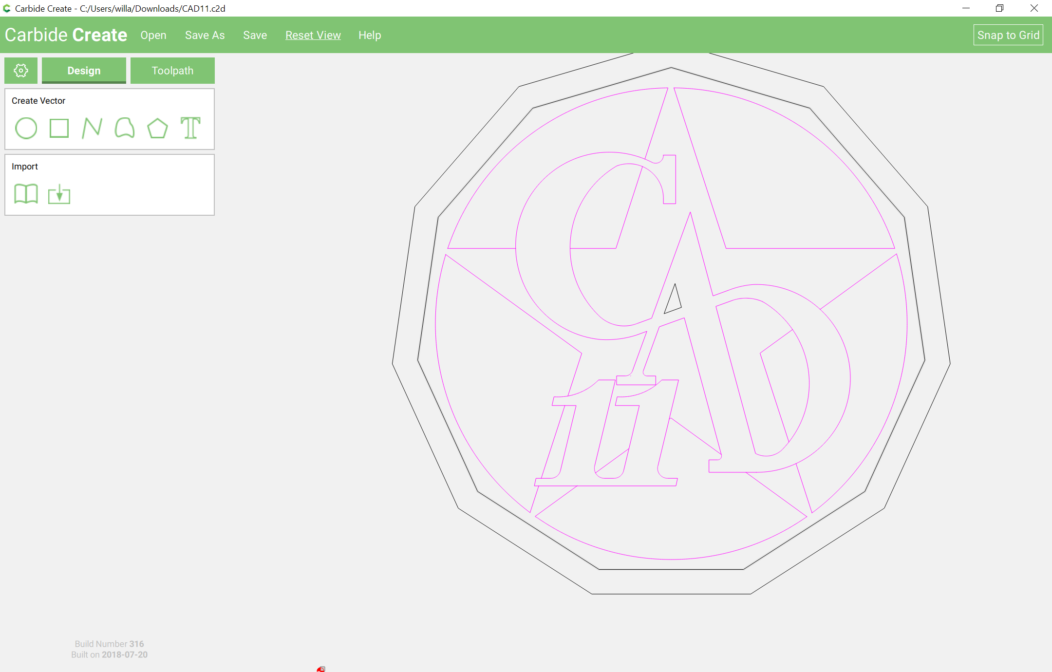
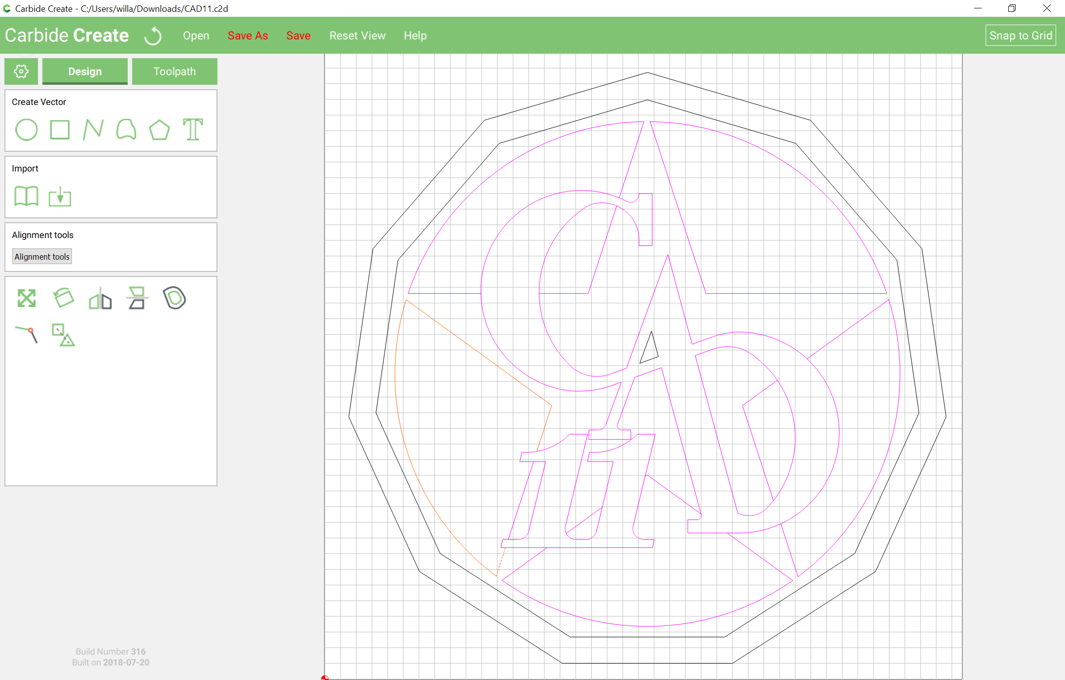
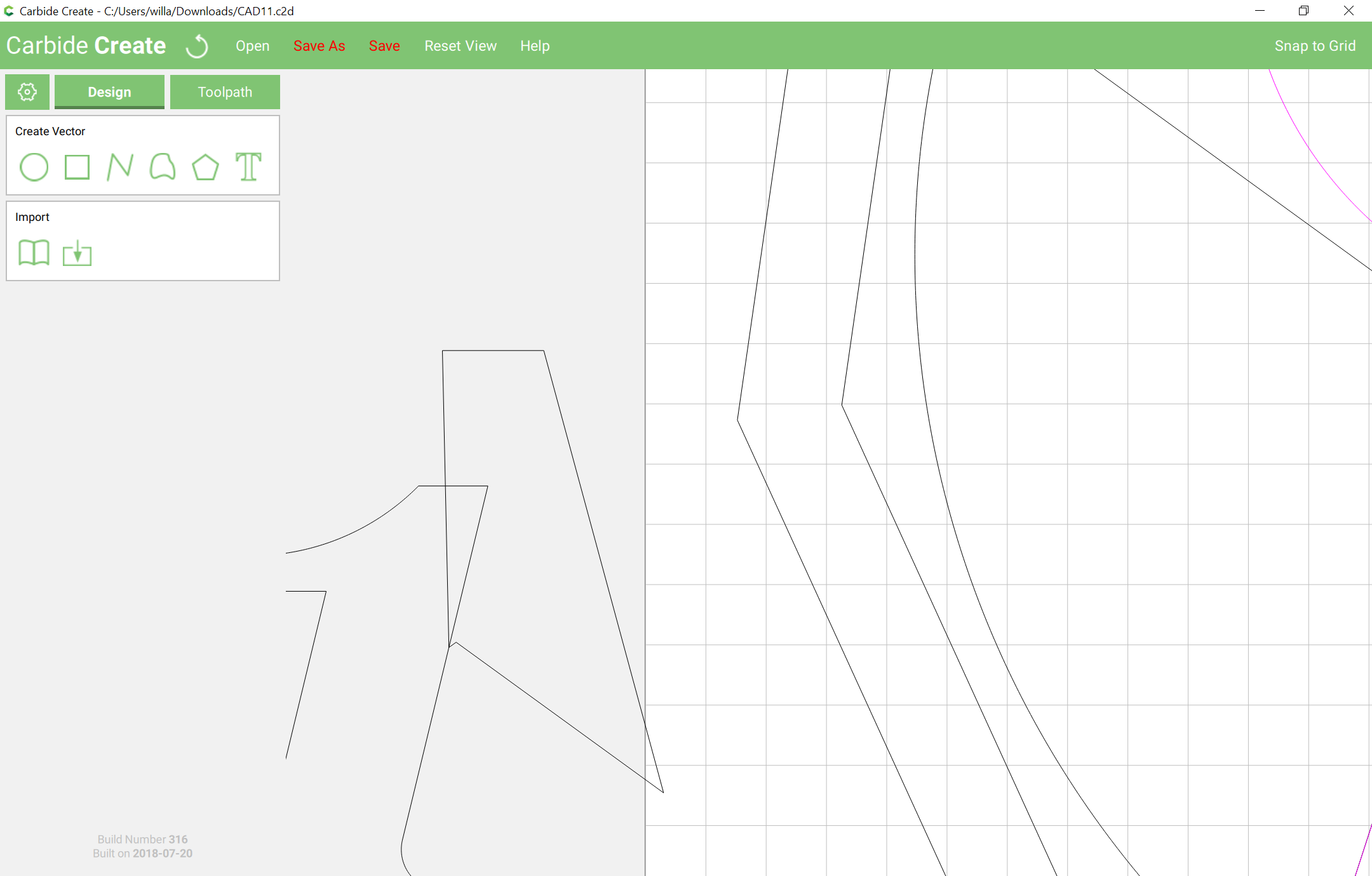
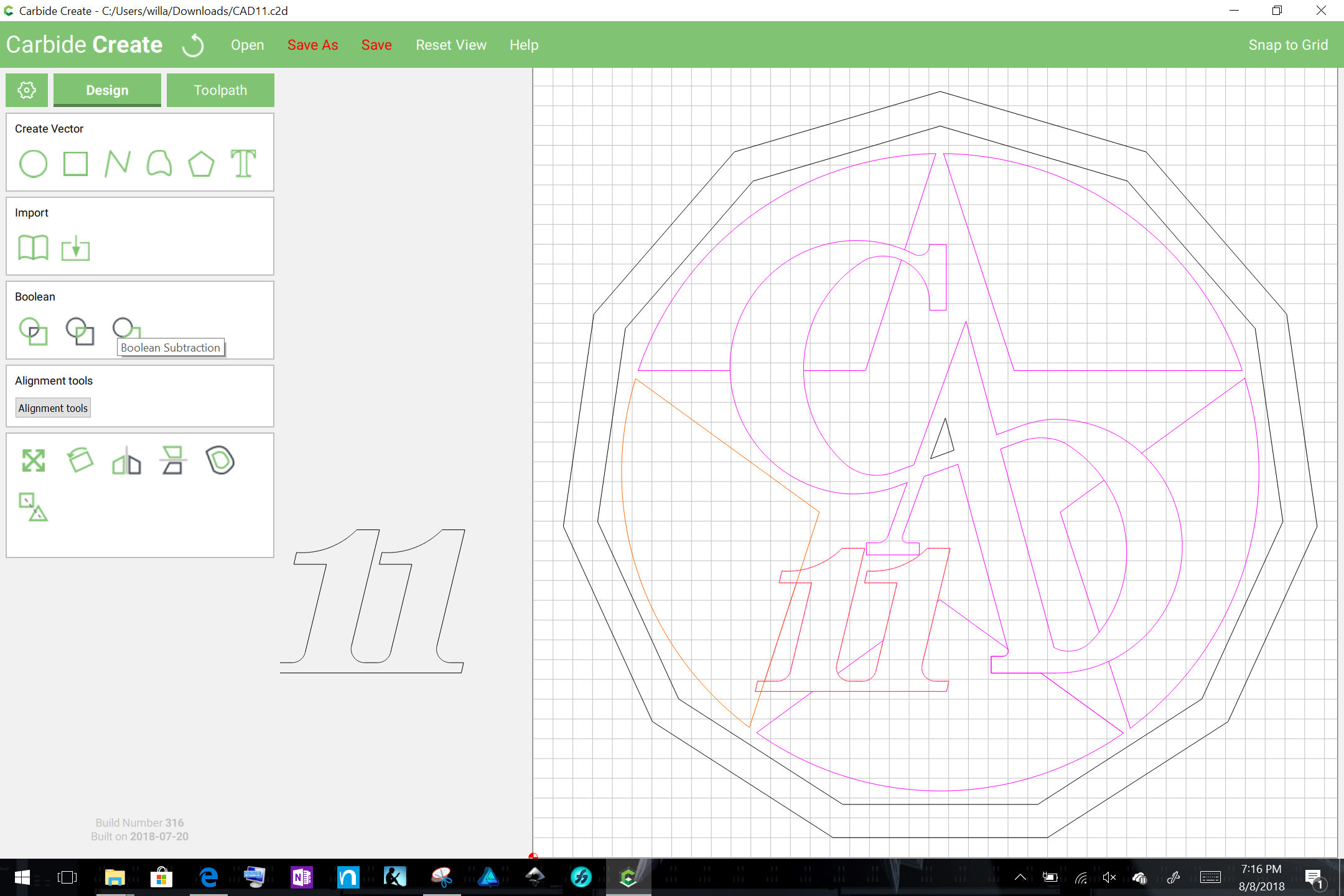
Although this is just an image I have saved it as .dxf (without the colour) and tried to create tool paths that ultimately create three different depths. The white being the deepest cut, the orange next and the black being the top of the material. My problem is that when I import it into Carbide create it just seems to select what it wants to and also some of the lines are purple (Which I believe means there are incomplete or dangling lines) But I have gone through very diligently and cannot find anything. I am wondering if this is not something Carbide Create can do…
Should be doable? I’m not super well versed with Carbide Create yet, but having run into a snag with a few objects imported from .svg you may want to draw lines/objects yourself with the curved line tool in carbide create.
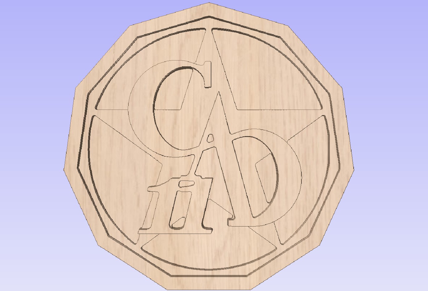
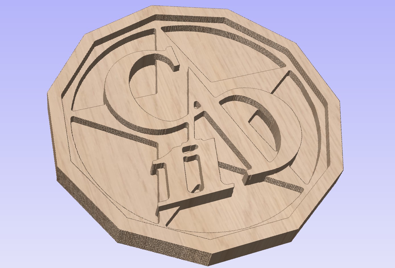
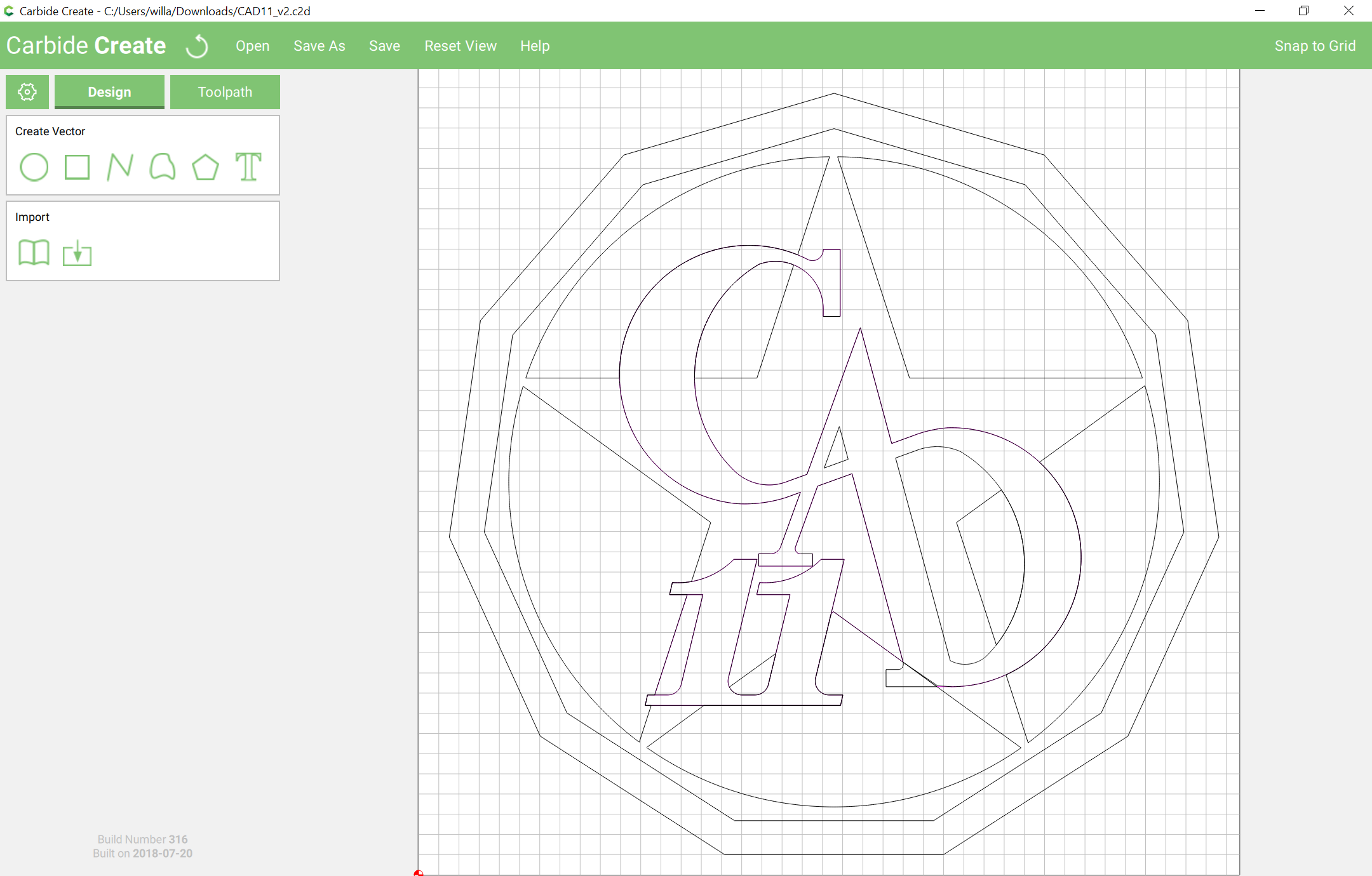
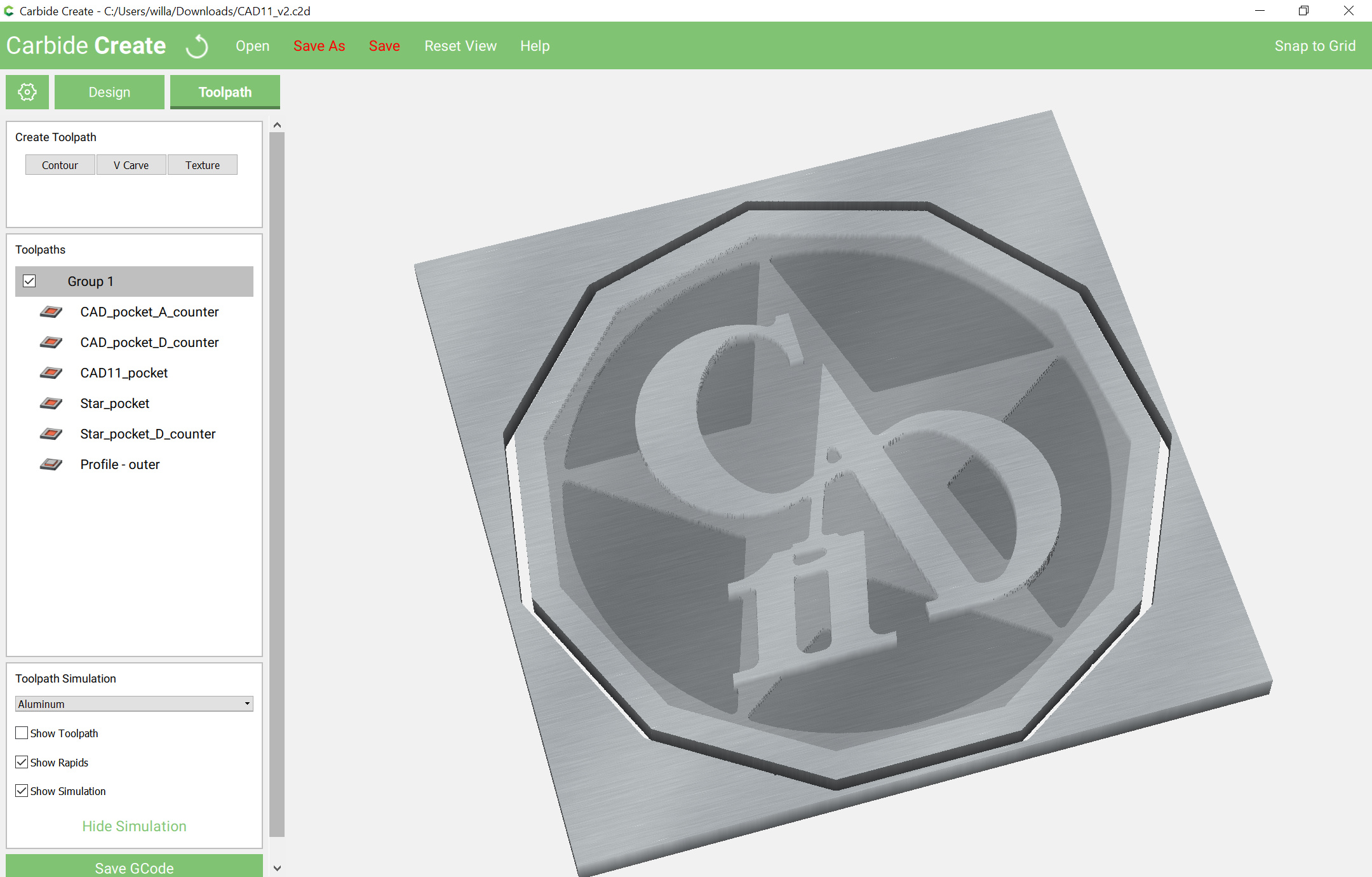
Great looking logo, I like how the C and D are one long curve. One issue you’re going to run in to with this image is going to be the sharp inside corners of your pockets, once you do get it into CC. The endmill, being round, can only give you round corners. This is the logo done at about 8.25" across, with a 1/8" endmill.
From the Z
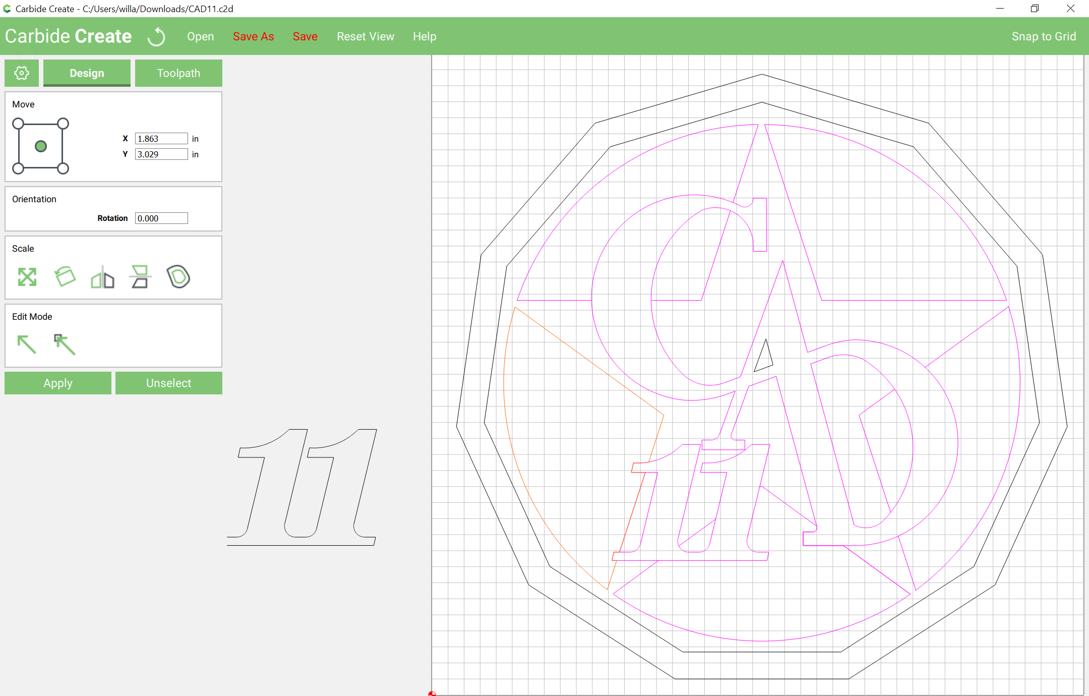
then click on the “Join” icon to combine them into a single path, then go into edit mode and drag nodes on top of each other so that they will then allow joining and closing of the path:
Repeat this for other elements — using Boolean union as needed to combine things. When one arrives at a point where one has elements which need to be combined: