
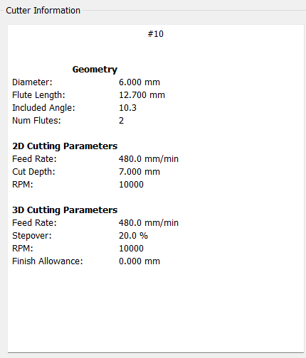
What tool are you using?
How is it defined?
Upload your .c2d file and a screengrab showing your Edit Tool window?
sure!
CornerProblem.c2d (29.5 KB)
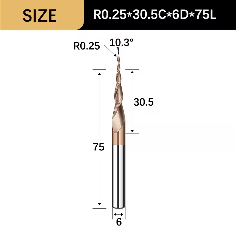
Also, link to the tool source/specifications?
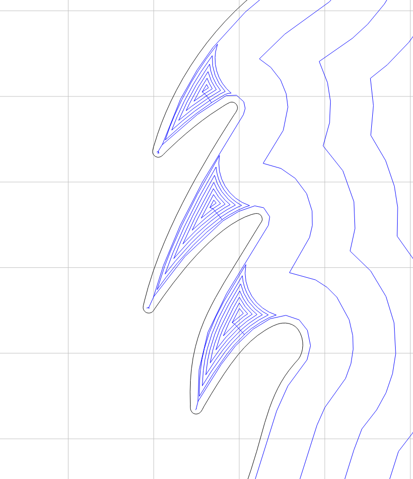
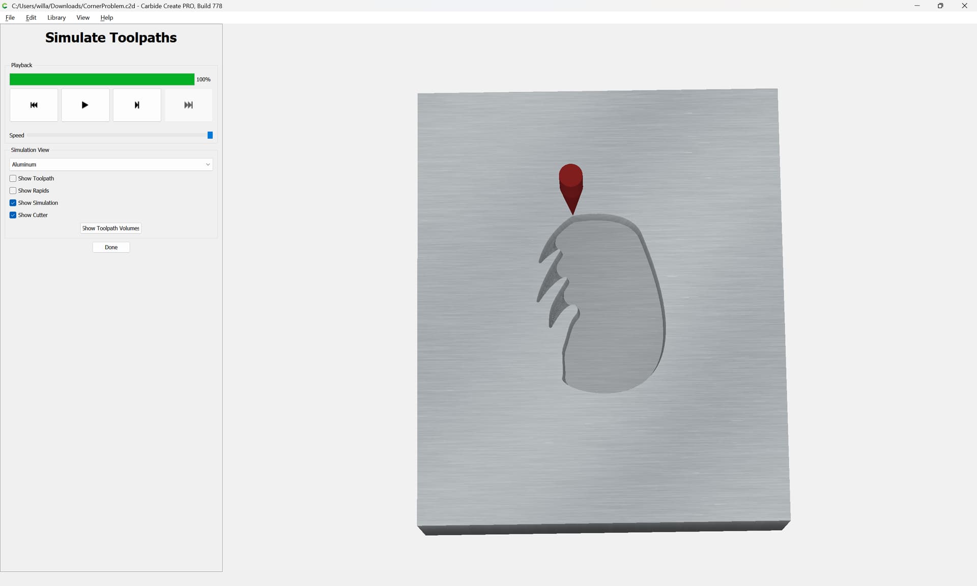
The 3D preview is fine:
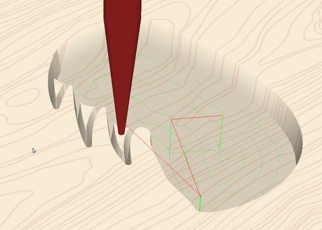
and a 3D preview of the G-code in a 3rd party tool matches:
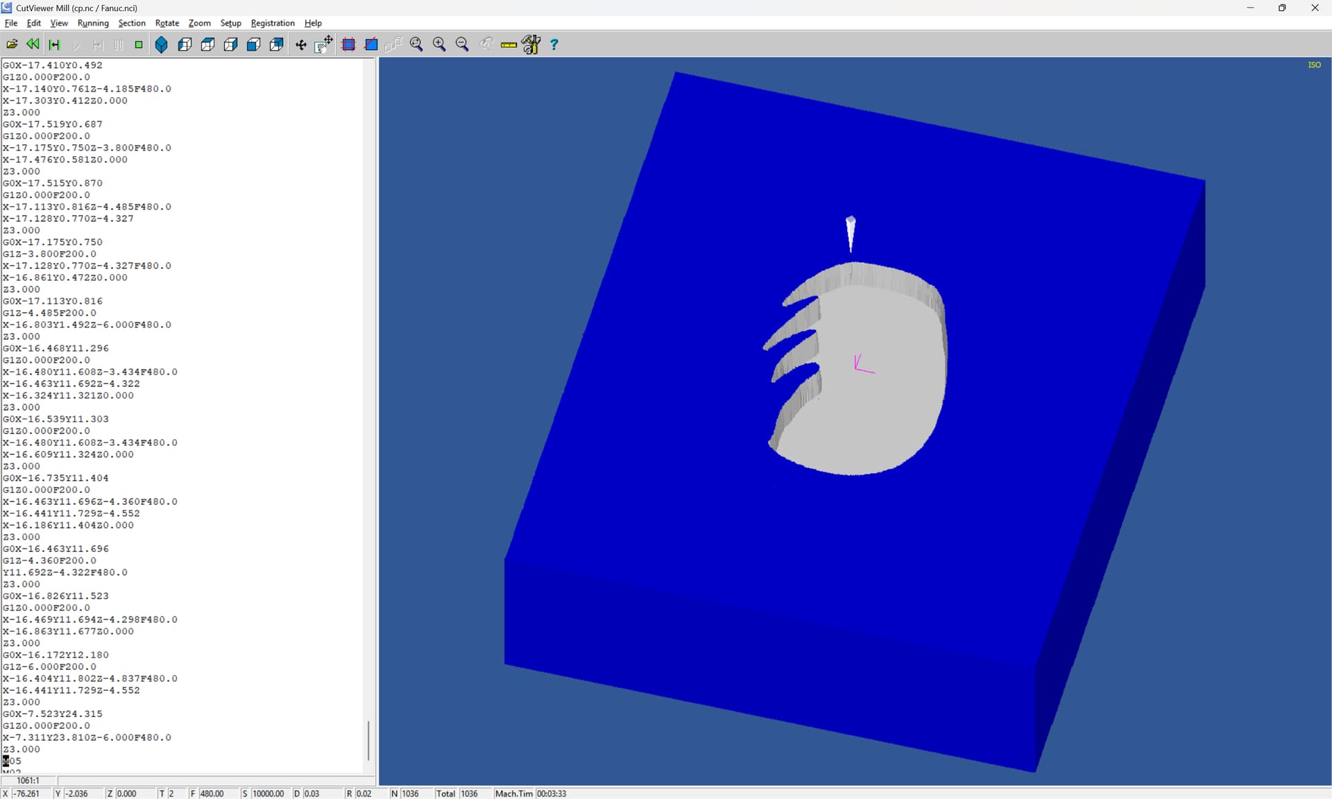
so I suspect that there is something wrong with the tool specification/definition, or feeds and speeds causing tool deflection.
Try drawing the tool up in profile, then spotting a pair of holes spaced to make an easily measured width at the surface between them, then measure the space between at the surface — if it doesn’t match, then do the math/measurements to calculate the angle and try that.
EDIT: and as noted by @DAH , Carbide Create does not support a tapered ball-nose tool geometry.
If my math is correct, that tool is 2.5 mm shorter than a true V tool so your zero is set too low. Are the circles about 0.5 mm diameter?
You can also look at it as the tool being too wide / having a tip diameter rather than a sharp point.

If you offset the boundary in by the radius of the tool tip (0.125mm), the size should come out right.
However, even leaving that off should not give the results he’s seeing, it would just be 0.125mm bigger.
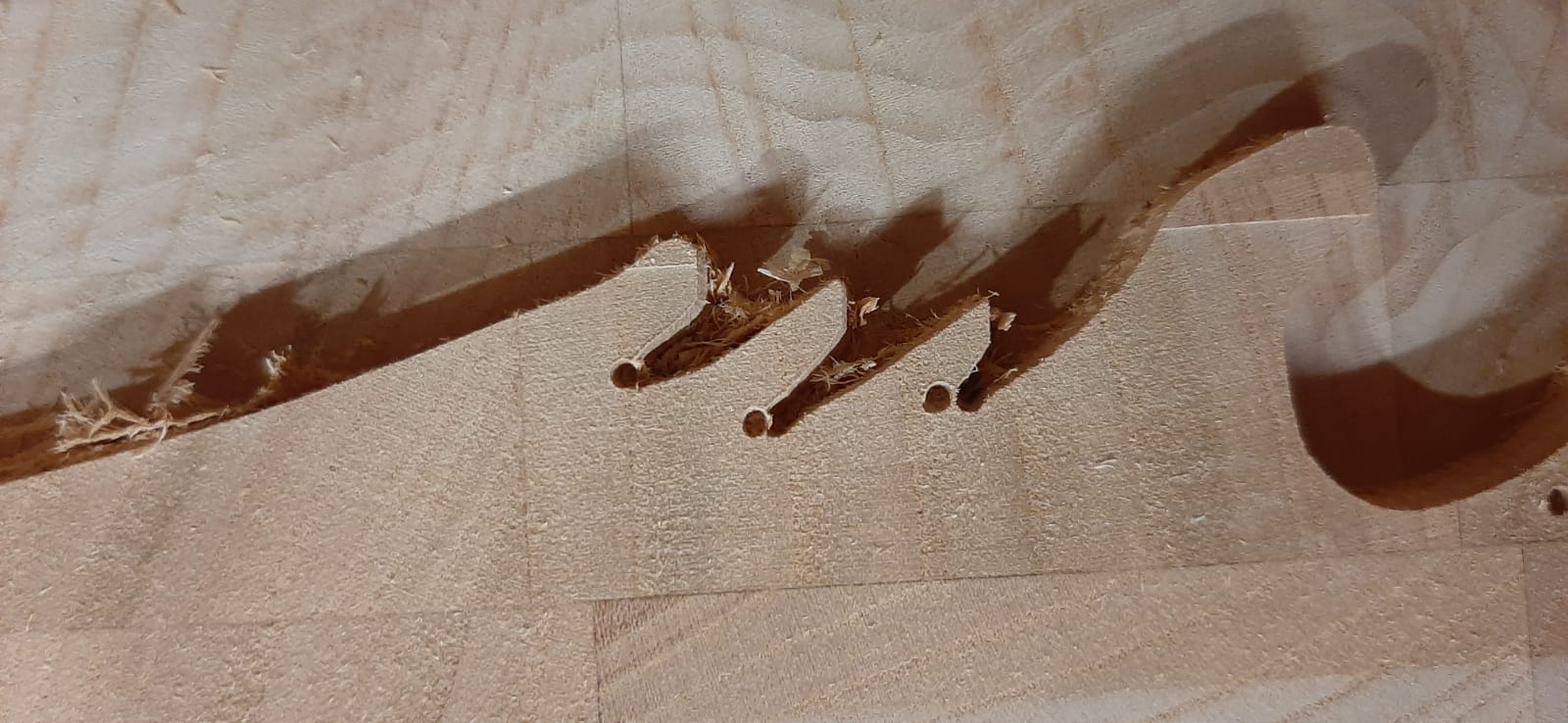
It almost looks like it didn’t finish. It picked out those corners before walking up that wall and never got to that point. V-carve behaves a little goofy in the way it orders the operations.
Or, it lost some steps somewhere in the process & those corners are in the wrong spot.
A little metrology (measuring the part) would reveal something. ![]()
yes, all of them seem to be the same size, which is 0.5mm. How do I calculate the true V tool so that Carbide Create thinks it has a point rather than a small 0.25 ball nose?
As mentioned, offset your boundary inward by half the diameter of the tool tip & use that curve to program.
Try doing a couple V-carves without clearing tools at 2mm & 4mm before the final cut with the clearing bit.
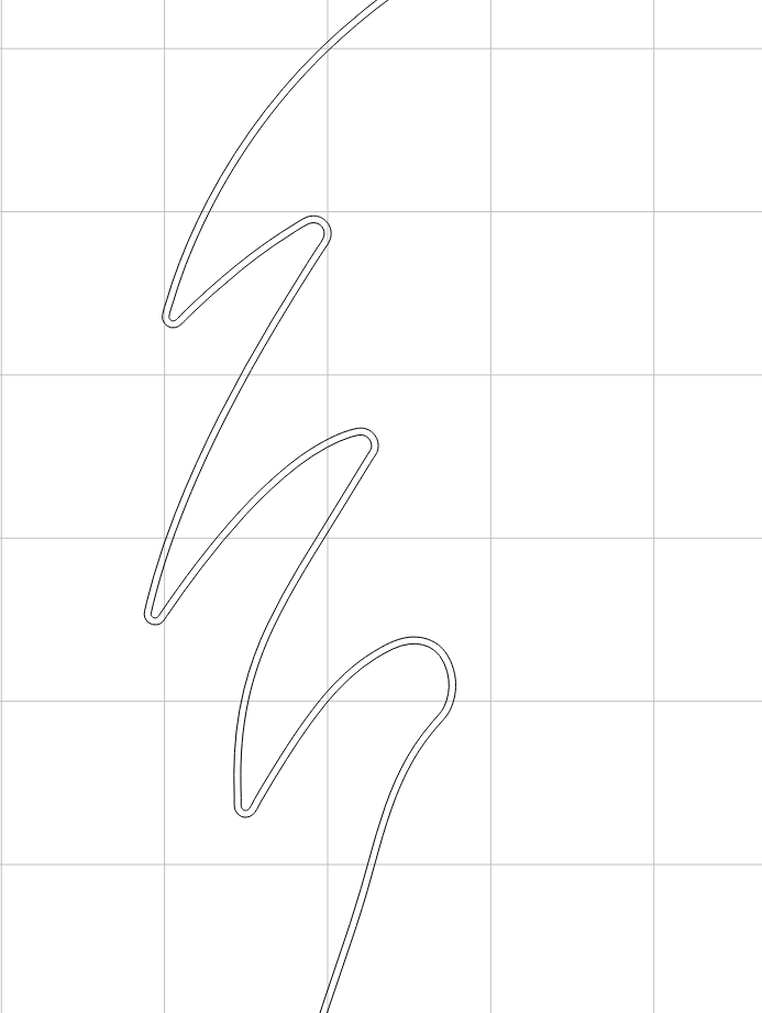
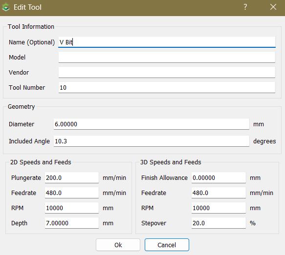
here’s what it looks like with the offset, but I don’t think that will solve my issue with the holes. I can only edit my tool with these parameters:

One thought is raising the bit by the hole depth and using that as a Zero point, but I don’t think that’s a good option.
So my question is how to calculate and edit the tool so that it thinks that it is a V-Bit with a 0mm tip radius rather than a 0.25mm with only being able to edit the bit diameter and degree?
CC does assume the bit has a sharp point. It doesn’t support tapered ball mills, so you have to improvise. If you’re finishing 3D cuts it’s a 0.25mm ball. If you’re V-carving, it’s a 10.3° Vee.
Offsetting the vector(s) just gets it to the correct size. If you measure across your cut somewhere with a known dimension, it should be 0.25mm too big.
If the holes are in the correct position, perhaps you stopped the path & didn’t let it finish?
If they are in the wrong place, then the machine lost steps & your zero moved. Taking smaller cuts can prevent lost steps.
If you step through the simulation, notice it cuts the periphery with the Vbit before cleaning out the center. It does some strange things when it has regions that have to be cleared with the Vbit.
thanks for the reply, I really appreciate it!
No, I always let the code run until it’s 100% finished, and the holes look to be in the correct position.
I did some calculations and came up with a solution, which is to put in a larger degree than the bit is, which should hopefully fix the problem with the holes.
The bit now is 10.3° and increasing it to 11.2° should hopefully fix it, but an easier option would be better.
If anyone is having the same problem as me, I found a simple fix that kinda worked for me.
If the flute length is wrong (in my case it was) then type this into your command prompt (windows + R) %LocalAppData%\Carbide 3D\Carbide Create\tools and click on your custom tool library excel sheet. Then edit the tool flute length and it should be better, hope this helps!
and also oil your machine! The holes went away after some grease and oil
This topic was automatically closed 30 days after the last reply. New replies are no longer allowed.