Until you start adding more components, then it changes back to the default (Mine keeps switching back to Cherry, which is also too dark to see details).
The hardest/weirdest thing for me to grasp was that the 3D in CC Pro is not a geometric model, but a gradient bitmap / height map. And the tools were just geometric parameters to create the bitmap.
The next epiphany would be the vector you select for 3D toolpaths is just a boundary, and it cuts any/all 3D geometry within that boundary. So you can model what Will shows above, but only cut a portion of it.
You don’t have dimensions, so I’ll guess overall 3x3x6. I’ll start with a 12x12 workpiece knowing I need some extra space for the 3D model, and I still want to zero at the lower left corner of my actual stock.
Draw the pocket for the part with vertical walls

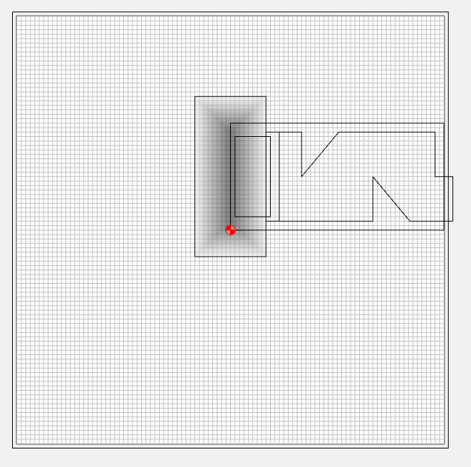
This is the actual box
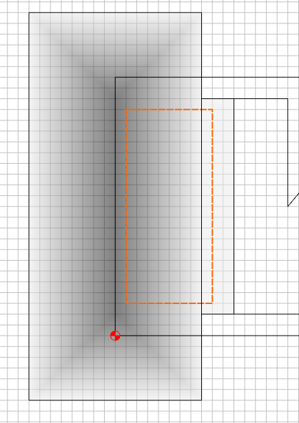
Draw the rectangle to build your pyramid / model. I also added another rectangle to make a ledge to prevent the 3D toolpath from falling through the back of the box.
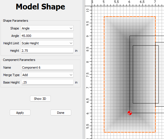
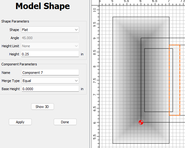
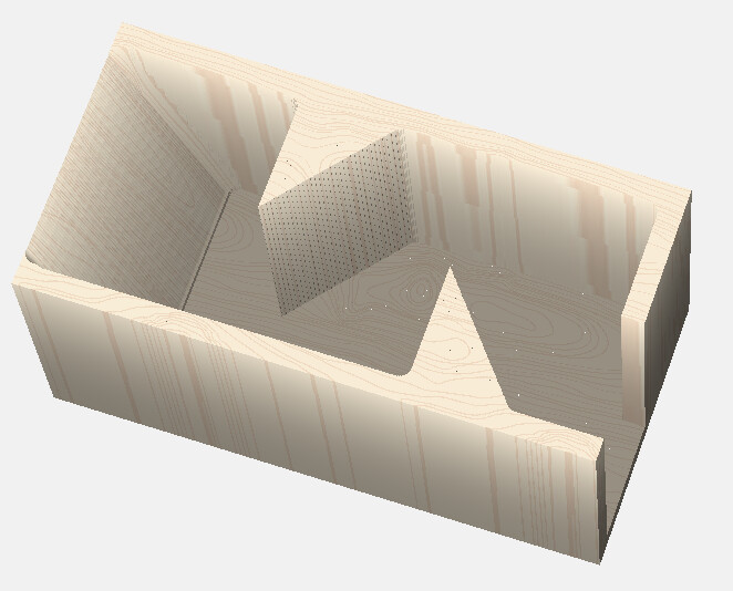
Model the pyramid. The angle doesn’t matter since it’s scaled. 2.75 is the 3" height minus the 1/4" back. The 0.25 base height starts the taper 1/4" above the table.
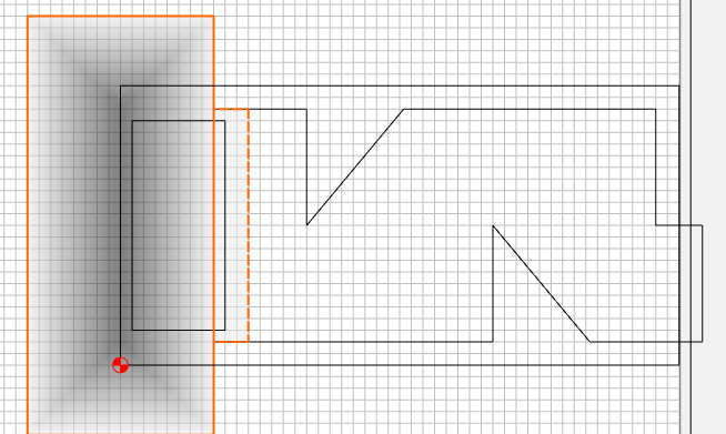
Make the ledge 0.25 high, and use the Merge Type: Equal. This will prevent the modeler from adding the edges that coincide.
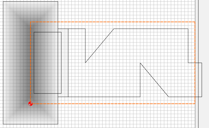
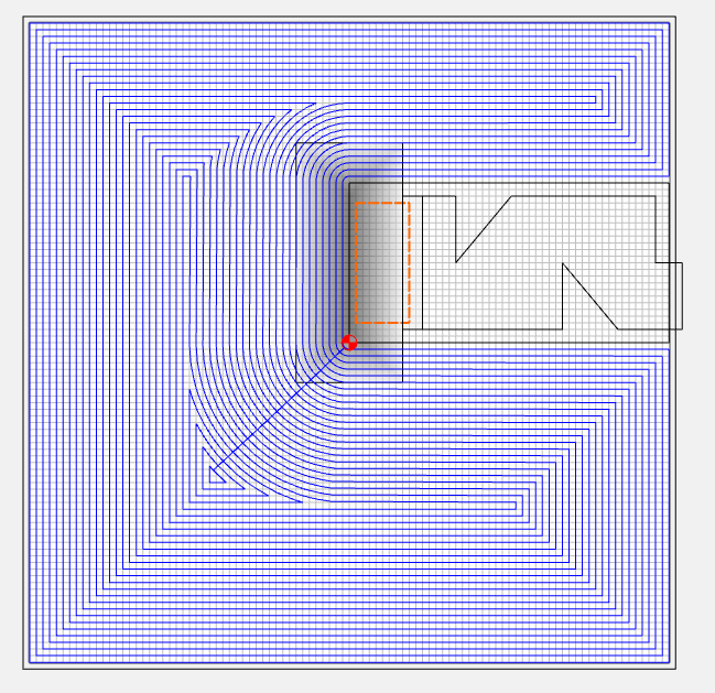
Now design the 3D toolpath boundary. 1/8" offset from the inside wall of the box. 3D paths drive the tool ON the boundary, leaving the radius of the tool outside the boundary.
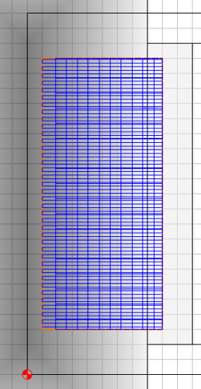
Mill out your main pocket
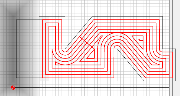
Rough & finish the angled surface using the boundary
I created a bogus toolpath outside to mill away the extra workpiece stock that really isn’t going to be there…
Leaving…
Justin_Dice_Box.c2d (72 KB)