Hi all,
I’m designing a compact dice rolling tower that will be cut on a CNC and require minimal assembly. I am trying to figure out how to make a “forward angle”. I would like to design this as two mirrored pieces and just glue them together to create a sealed inside (see drawing). I have cut topo maps and am familiar with cutting 3D shapes from grayscale or STL. However, this seems like it should be simple and less “hacky” than generating a grayscale image in photoshop or modeling an STL in another application.
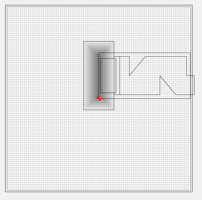
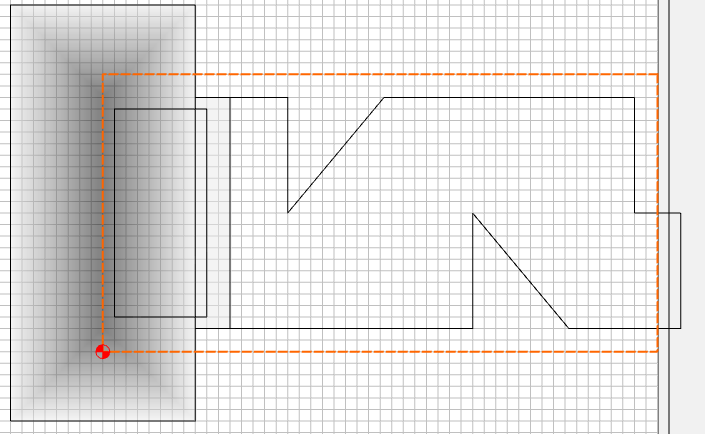
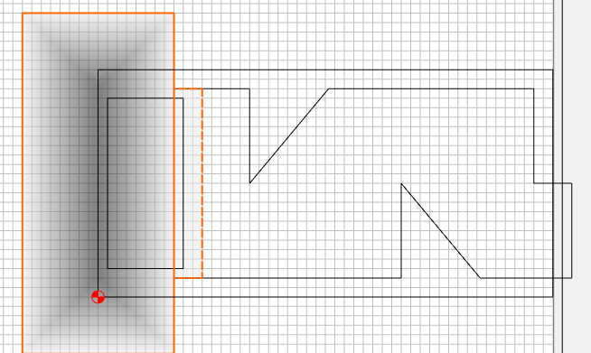
Here’s a diagram:
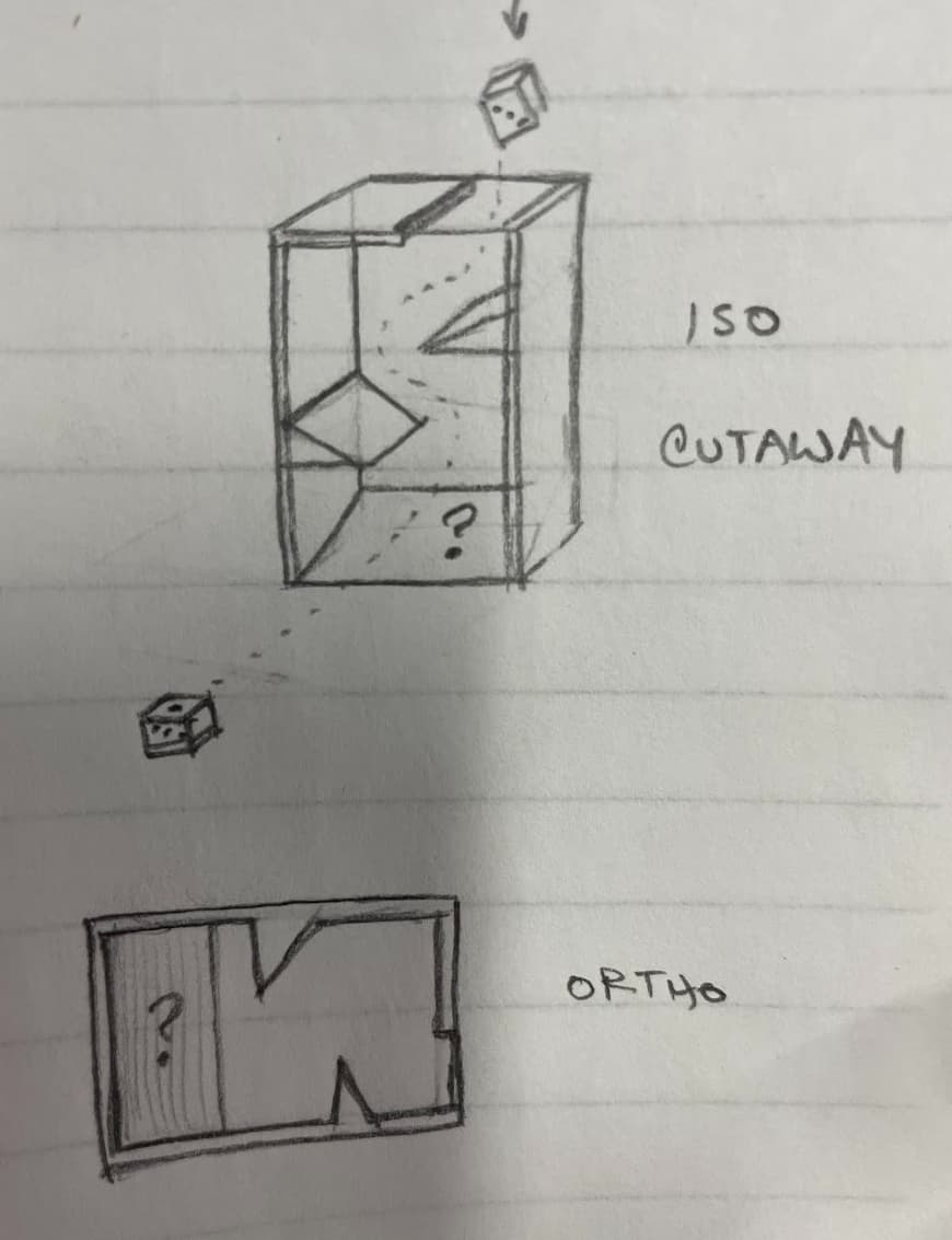
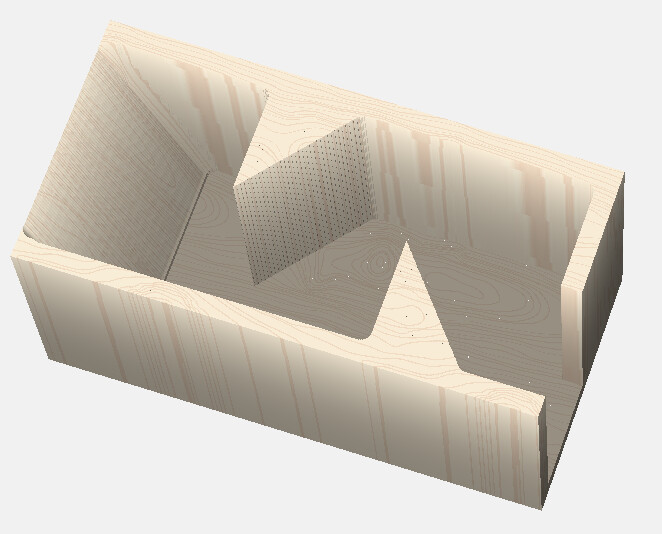
In the isometric cutaway sketch, you’ll see that the die is dropped in a hole in the top, bounces off two angled surfaces, and then is ejected in the front by an angled surface. This is the surface I’m struggling to create.
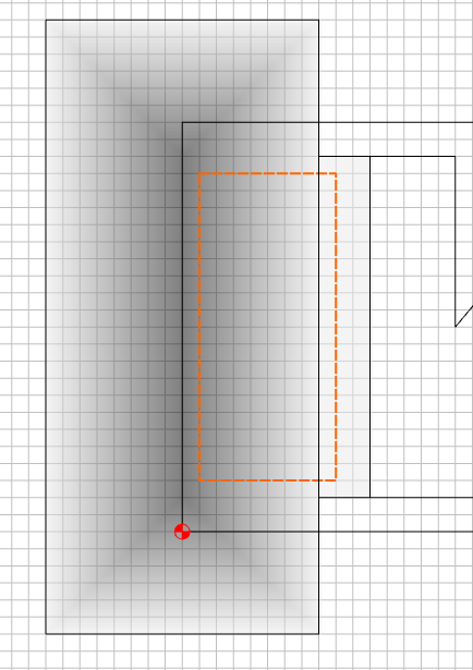
In the ortho view, you can see that cutting the first two angles is easy since they are 90 degree cuts into the work material. But the final angle needs to ramp with a rough and finishing pass.
I could:
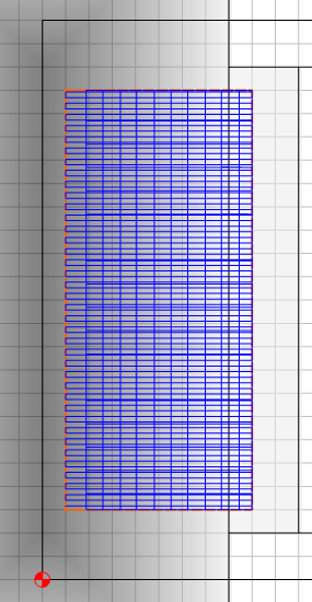
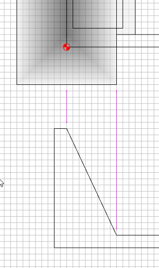
- Create a grayscale gradient in photoshop that results in a linear angle
- Create and import an STL file for the forward angle
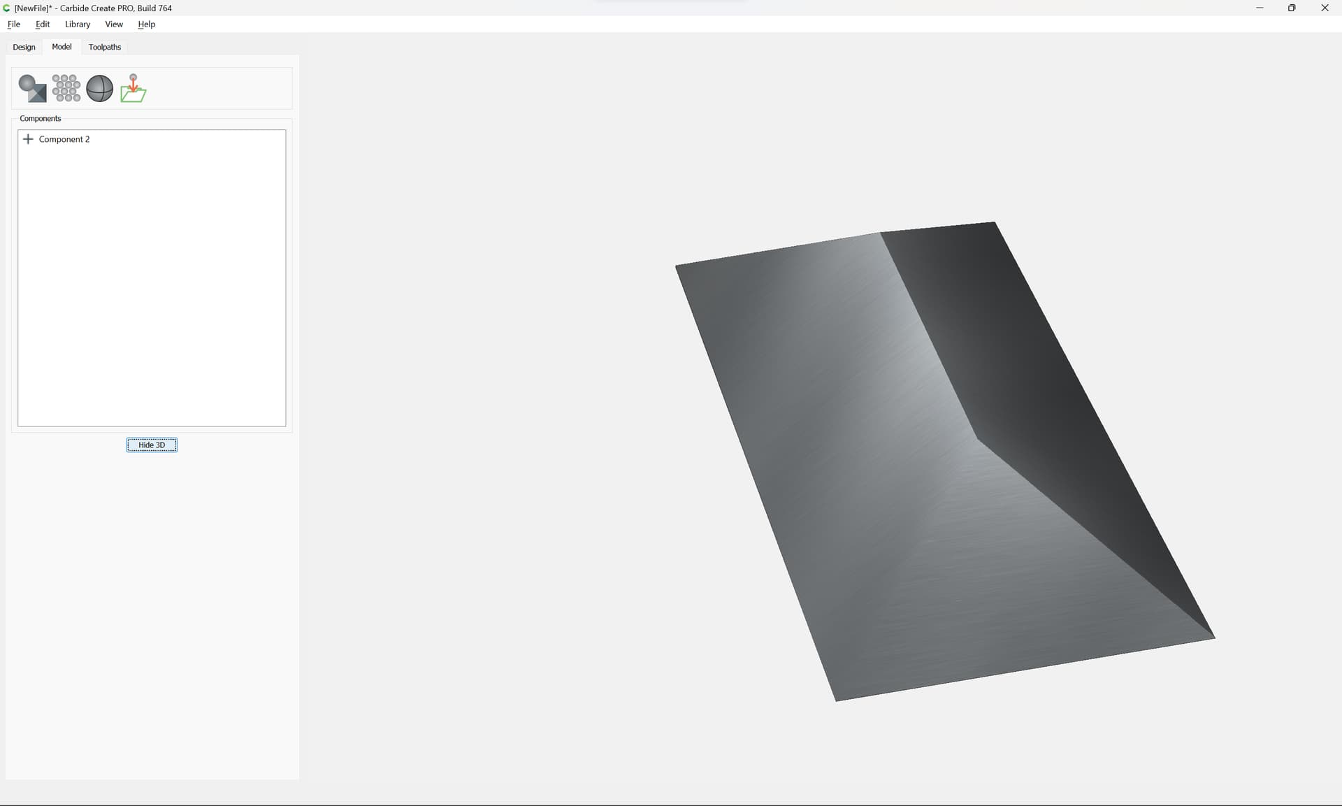
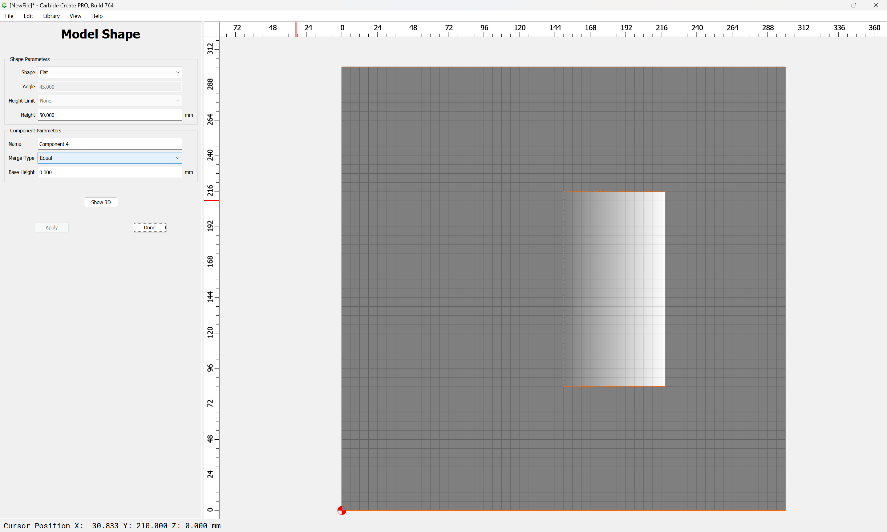
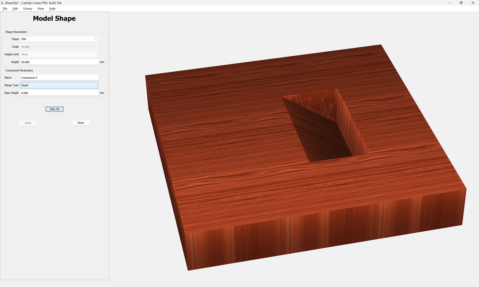
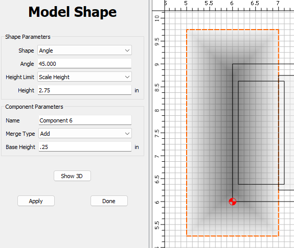
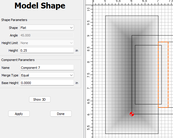
- Use 3D shape components?
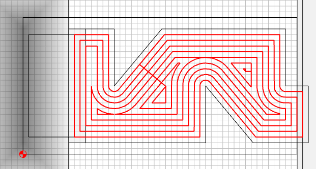
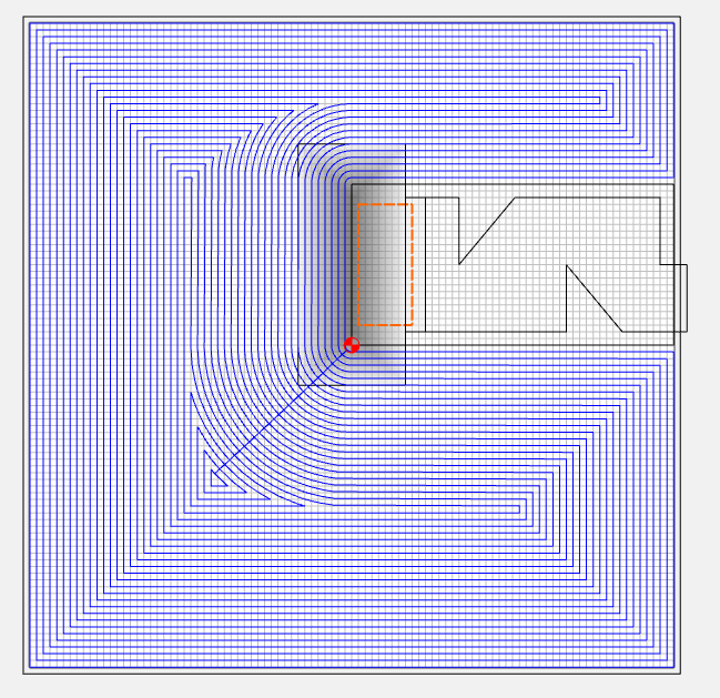
The first two seem hacky but I can’t make sense of the 3D shapes. I would assume I could create a round shape in “subtract” mode and subtract it from the work material but this results in no 3D preview and a toolpath that cuts all the way through the work material.
Is there an easier way to do this?