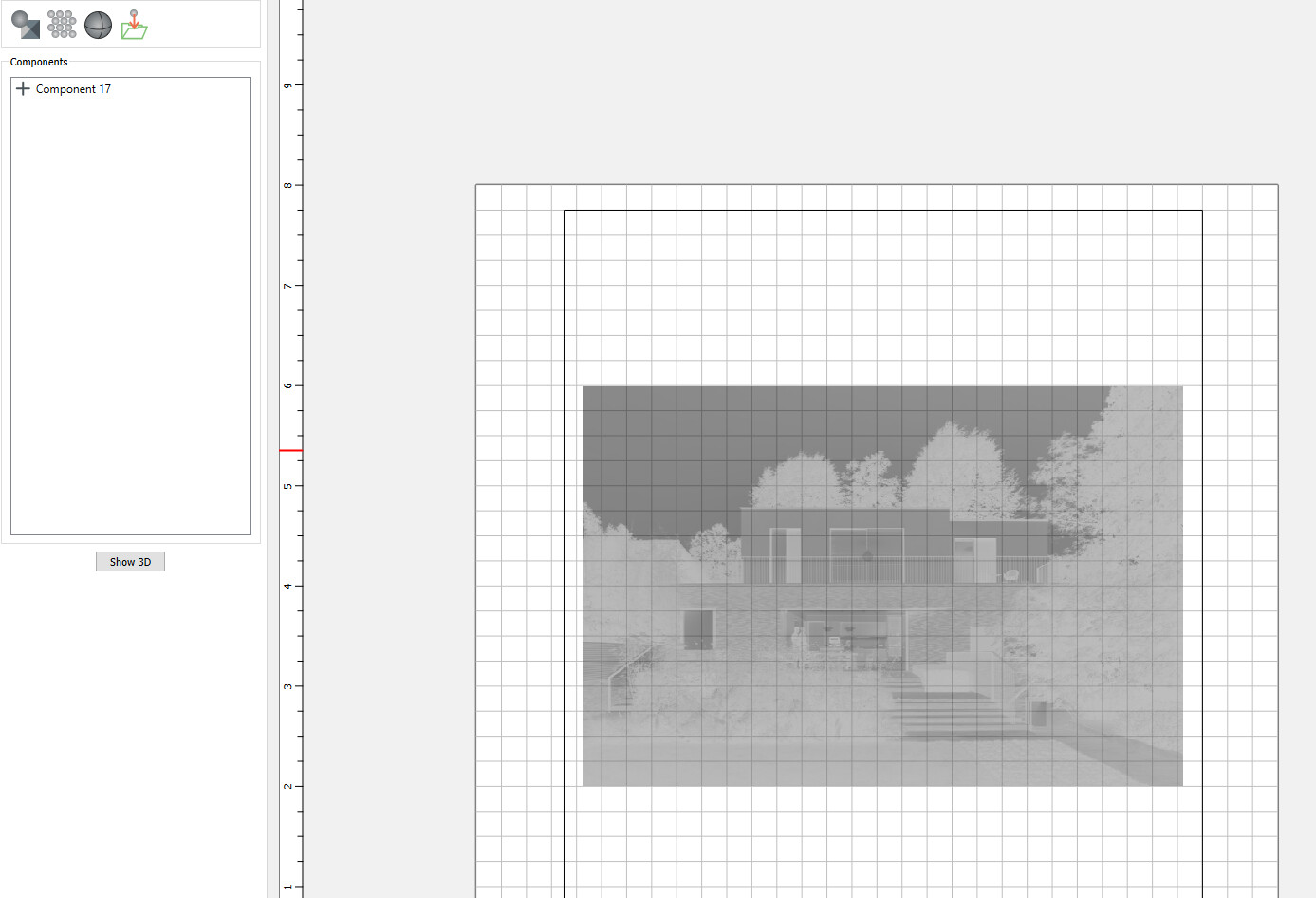
But now if I simply want to cut this out…I got to my ToolPaths. Click 3drough and it doesn’t I have a valid layer. This seems like I’m missing something really simple. I’ve been watching the tutorials but it seems it doesn’t make that part obvious. https://my.carbide3d.com/gswccpro/06/
Ohhhh, I see, you have to explicitly put a (square) vector around the image and then the 3D Rough and the 3D Finish will make their paths based on the grayscale image.
So next stupid question… at the https://my.carbide3d.com/gswccpro/06/ 8:40 mark he shows the rings and they are essentially only at the “surface” of the piece. I think he did a height of 2mm of his rings and then made a backer of 3mm giving a total depth of 5mm. To me this implies that the total depth of his entire cut out will be 5mm. His Stock to leave is .5mm. Did create his initial stock to be like 6mm (leaving .5mm) so it only looks like its at the surface?
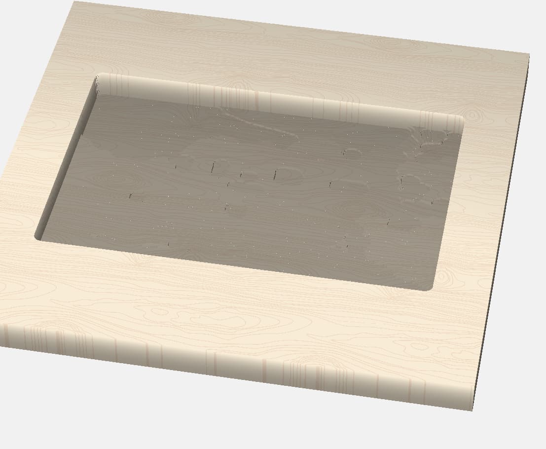
Well in my roughing toolpath selection it shows “stock to leave” is .0197" (or about .5mm) at default. But my toolpath cut out looks SUPER deep.
Obviously I can do some math to change the “stock to leave” setting but seems like there should be a way of cutting only as deep as the backer (3mm) + image (2mm) into the stock? Or did he have just a super thin stock (6mm or so) and it only looks like that?
Short, is there a way to make it only cut to a depth of the depth of the image + the backer? Or is there a reason why its done this way?
so when you make the 3D model side, you can (and should) put a “base” under it (its in the bottom half of the dialog)… and this is where it gets slightly weird.
You defined the stock depth in the project settings, and for best result, the sum of the height of the model and the base should be this stock depth value
so if you have say 0.75" stock, and the 3D model is 0.2", you put in a 0.55" base value
(think of it as a block that goes underneath your model)… 3D models build from the bottom up, unlike most other things in CC which go from the top down… the stock depth value is where these two meet.
Ohhhh that makes sense. Thanks. I just tried it and it works. The name I assume is “Base Height”.
I’m still trying to figure out how the “Include Ambient Area” plays into this as well. I’m watching the video and have watched it like 5 times I feel but can’t understand how to think about it if I have the base thats 1" thick and I’m only cutting .1" deep with my image.