Hi all,
I’ve been using Illustrator to do my guitar designs for a few years now, and now that I’ve become one with the Carbide Borg (and happy to have been assimilated), I’m running into an odd issue.
I’ll export my design as an SVG from Illustrator, then open that SVG in Carbide Create.
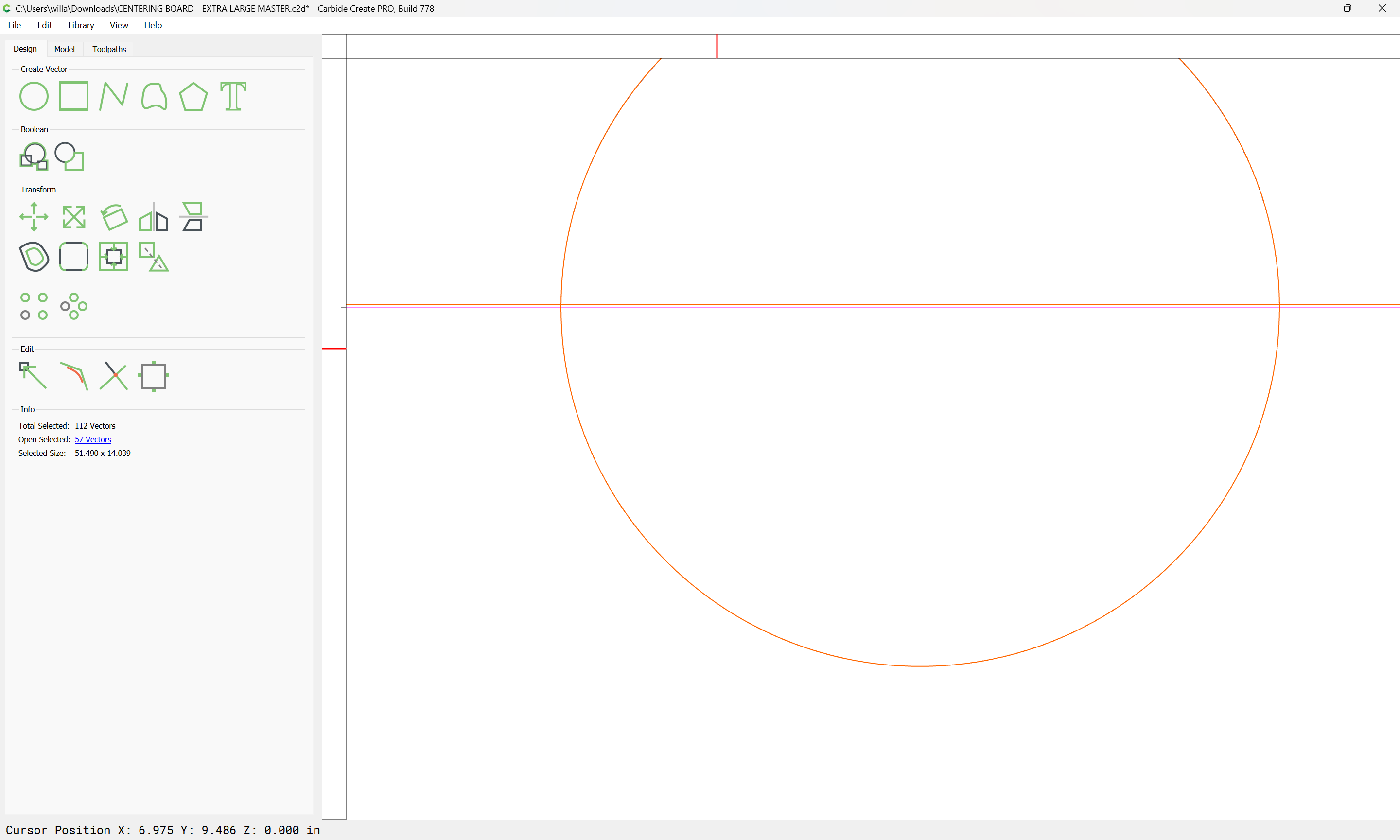
I have a set of indexing holes that align with a specialized wasteboard I made specifically for my guitar shenanigans. What I’m finding though, is my round indexing holes are not coming into Create perfectly (and therefore, I can assume, neither is anything else). For example, an indexing hole in Illustrator set to 0.2508" x 0.2508" will come into Create as 0.2508" x 0.2505", or something like that. I know that we’re talking a few 10,000ths up to a couple 1000ths of an inch, and most likely it will never be a real issue, but I’d still like to understand what might be happening here. Would love for this to be a perfectly 1:1 process from design through implementation. Anyone else run into this and/or have a fix?
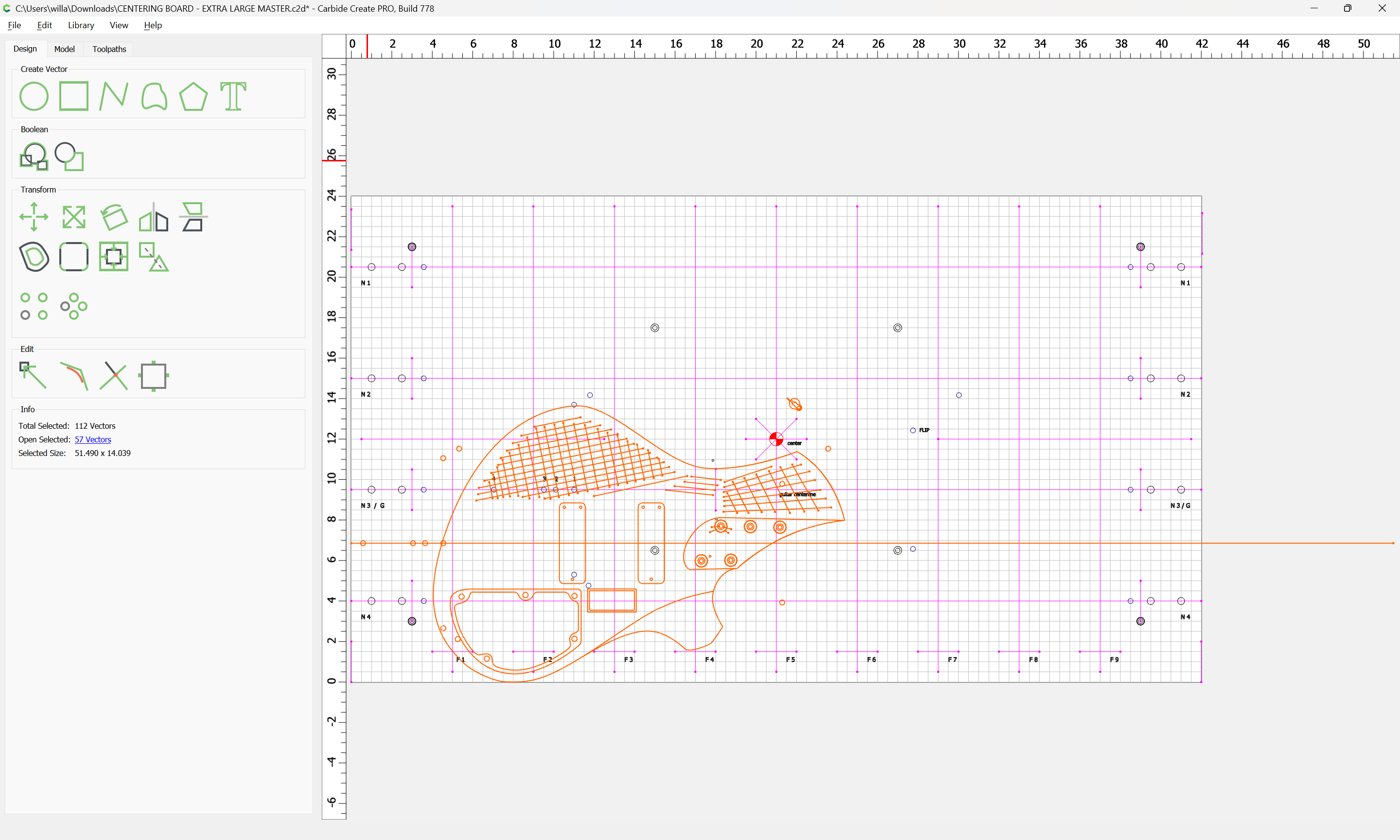
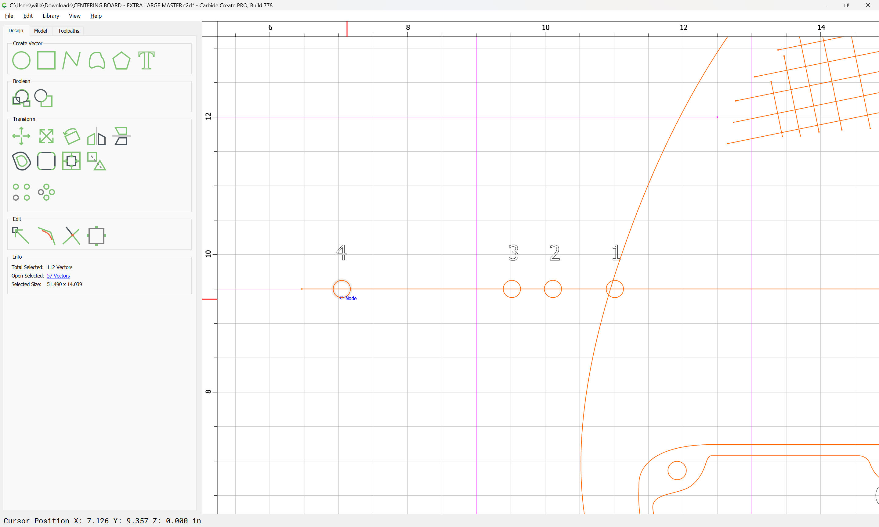
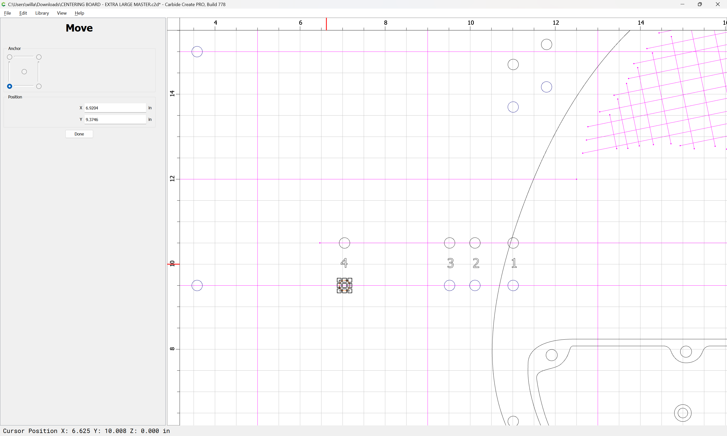
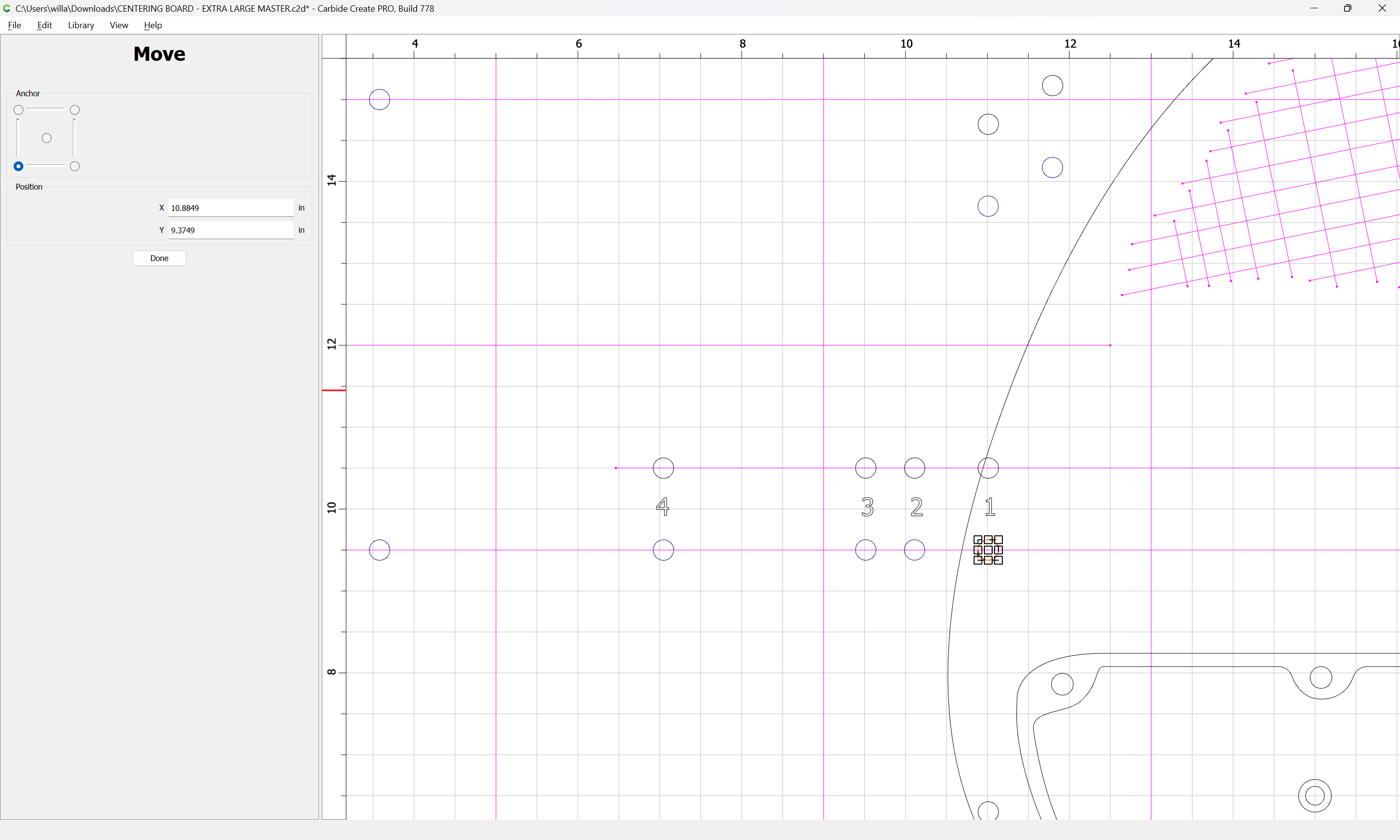
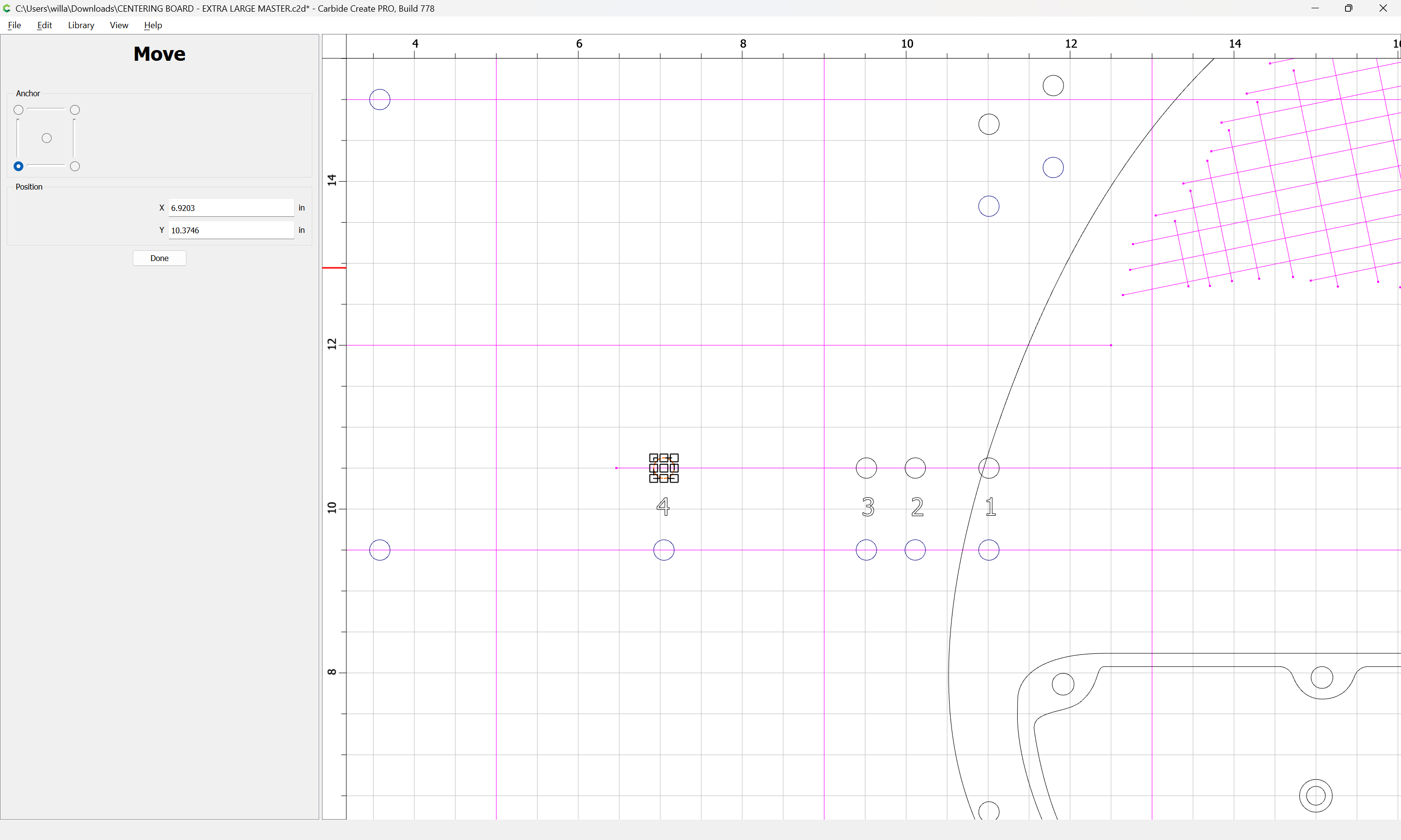
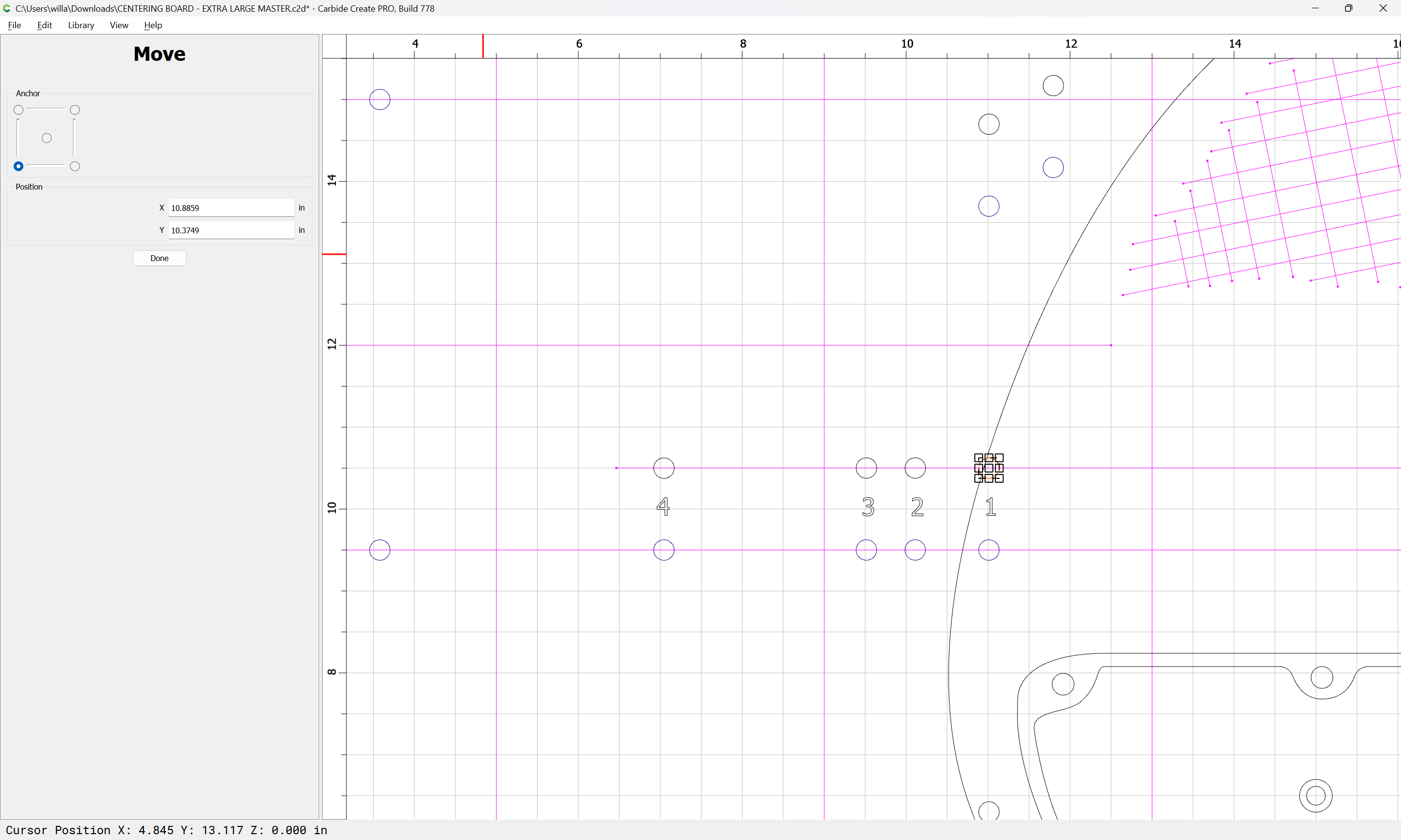
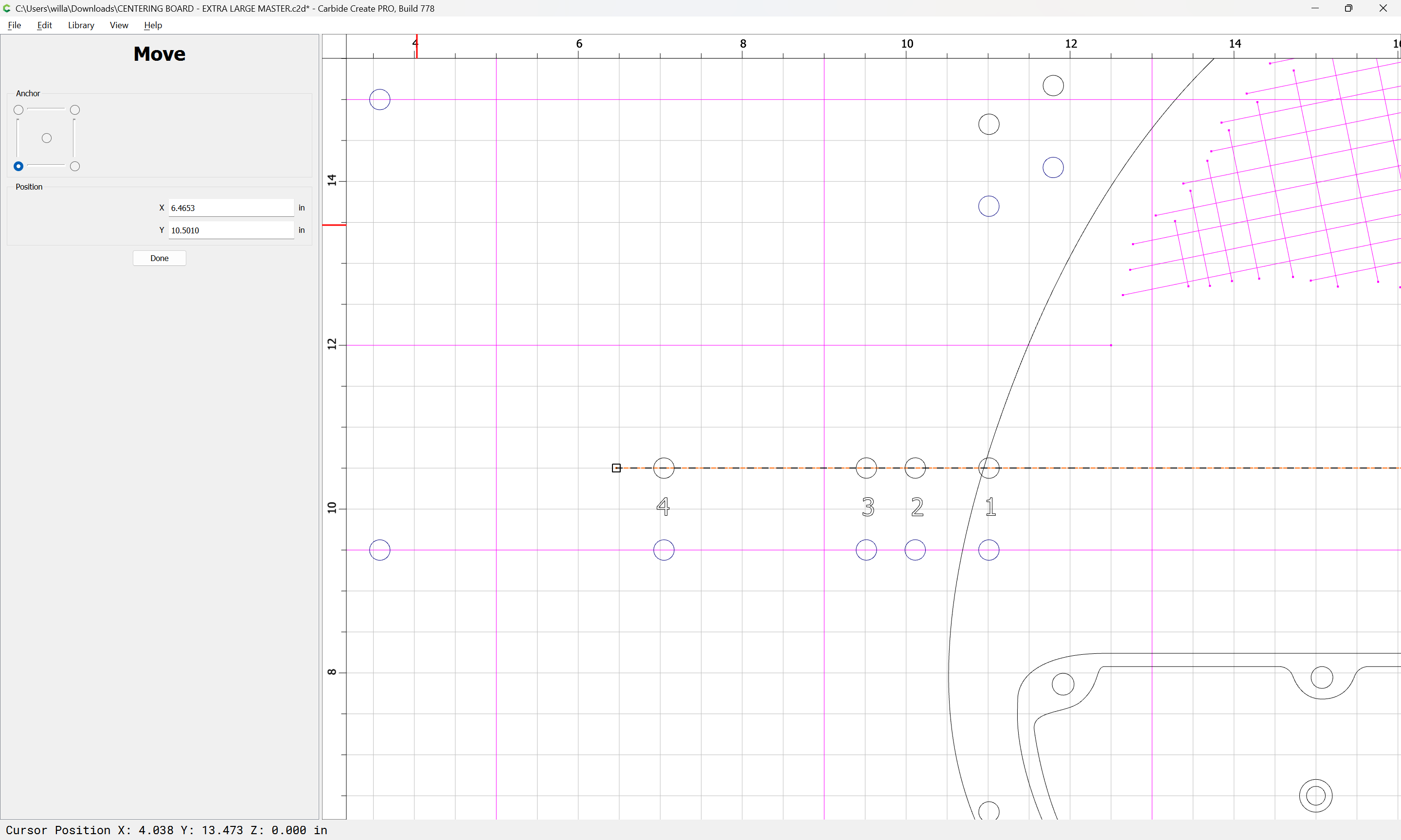
They are, but let me elaborate a little more - I’m attaching the centering board I’ve created that’ll allow me to knock out four necks or nine fretboards in one go, but also allow me to use those indexing holes to precisely align a body and cut pickup cavs/neck pockets, etc, then flip it over and do the control cavities. I know the array of holes seems a little weird, but that’s because before I got the CNC, I used a series of acrylic templates I cut on a laser table and that pattern of holes was ideal for that purpose. I decided to keep the extras in the new design in case I need to revisit something with those old acrylics. Anyways, if you open up the body SVG or Carbide Create file, copy all, then open this baseboard and paste the holes onto a new layer, if you perfectly line up (for example) the farthest left hole on the centerline to hole #4 on the board, then go and look at the lower left hole near the guitar’s lower horn, you’ll see things don’t perfectly line up - it’s off by a tiny bit.
Again, I really don’t think this small amount is ever going to present a problem, but I’d love to know why it’s happening. CENTERING BOARD - EXTRA LARGE MASTER.c2d (544 KB)
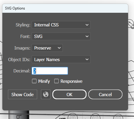
Is this related to Carbide Create expecting all vector files to be created at 96dpi? I have had this issue on several occasions previously when exporting vector files into Carbide Create. I was told that all vector files were to be created at 96dpi if you want 1:1 size equivalence on file export from any vector creation package.
My own understanding was that vector files were resolution independent but when creating .ai, .eps and .svg files in software like Illustrator or Affinity Designer, one should ensure that the resolution is set to 96dpi when exporting files to Carbide Create. Doing that has fixed all my size transfer issues and the files are accepted into Carbide Create at the precise size I create them. This has worked for me with files that were created to three decimal places.
It could be, but I’m having one helluva time finding where to set Illustrator to, well, anything when it comes to anything other than printing. The SVG export doesn’t have that option, and when I set the print parameters to 96dpi I still run into the problem in Carbide Create. I’m going to keep poking around but I think I’ve got a suitable workaround for the time being.
Hey - sorry it took me a minute to respond. Life got crazy.
Some of the oddness when zoomed in all the way turned out to be the centerline in my Illustrator drawing was set to .25pt instead of .1 (hairline), and for reasons I don’t fathom, sometimes it would snap the index circles to the top of the line, sometimes the bottom. I was expecting it to always snap to the actual path. Very weird. I’ve fixed all that, but the root issue still persists. It occurred to me, however - as long as all my designs have whichever of the numbered index holes required for that particular design - then I can pull in the .svg file, -just- use the numbered index hole for precise placement, then use that and one or two of the other baseboard index holes which exist on a different dedicated layer and are always consistent.
I’m not explaining this as well as I’d like - but in essence I created that baseboard design with all the index holes and centering lines, and I duplicate it as a starting point for every instrument. I’ll load the svg guitar file onto a new layer, now just match up the centerline/one of the numbered holes, and when I create to toolpaths I use the -baseboard- index holes, which will always be exactly the same.
I’m still going to see if I can sort out why there’s an inconsistency between Illustrator and CC, but for the work I’m doing it really has no impact.
Interesting read! I’ll have to experiment with the different methods and see if one solves it.
I’ve been doing the plain export option, always have minify and responsive off (tho I might try minify on and see what transpires). I changed the decimal up from 2 to 4, but that didn’t seem to make a difference either.
There should be an option in Adobe Illustrator to set measurements to the path itself, rather than the outline of a stroke, which should yield the desired results. (That that is not the default is just one of many reasons I loathe Adobe Illustrator).
And of course, Illustrator’s language within the Preferences is anything but logical. I’m totally with you, if it wasn’t for some external forces necessitating me staying with Adobe, I’d dump the whole lot and go with Resolve and Affinity. I’m probably going to grab a copy of Affinity regardless and see what that’s all about. I hear very good things.
In my opinion, this is a really good move. Affinity Designer was written from scratch and does not have any of the legacy baggage that Adobe software is beset with. Illustrator was frequently behind the curve when it came to Adobe’s much vaunted updates which usually fixed… almost nothing.