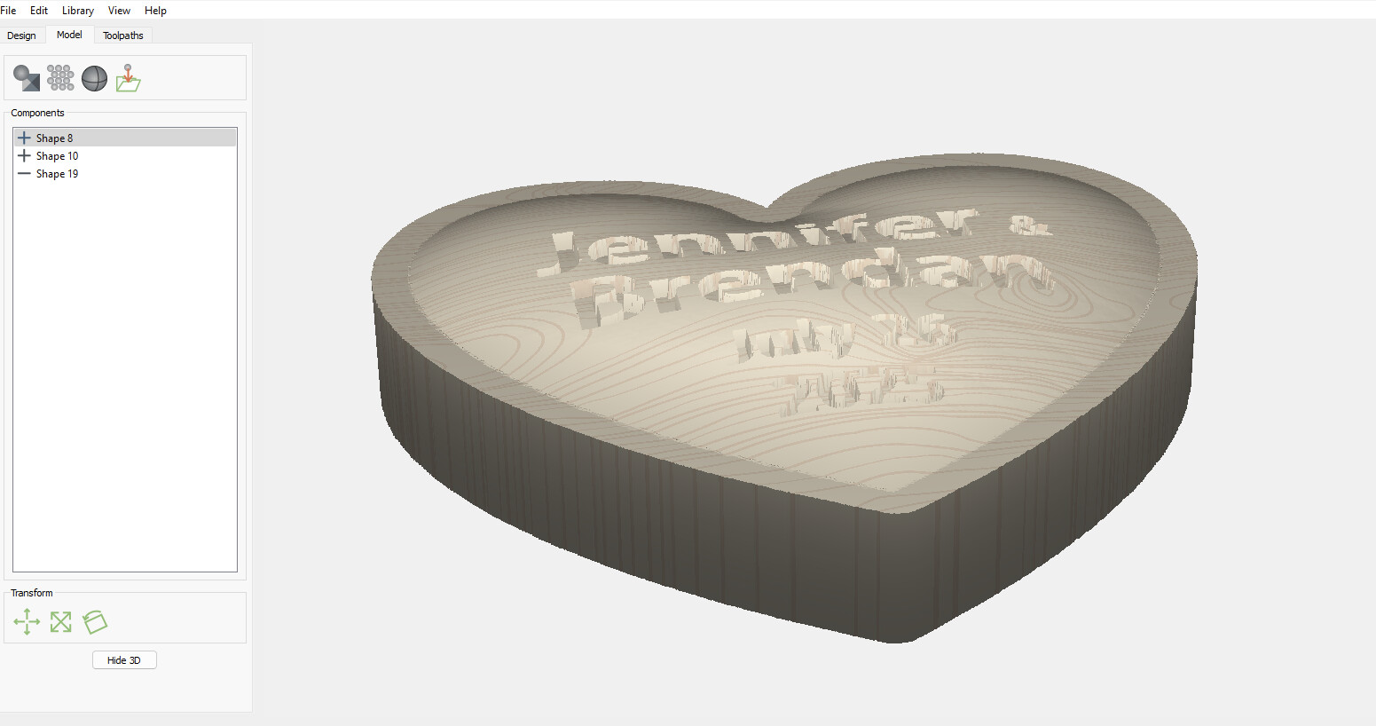
Trying my first 3D carve with the newly released Carbide Create V8 Pro. Took me a while to figure out how to design what I was looking for but got it looking right in the modeling preview tab.
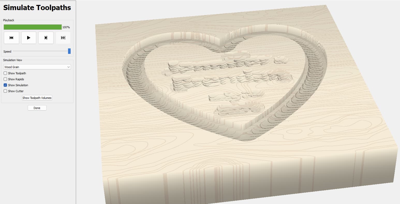
However, when I go to the toolpaths and select my 1/4 bit for roughing and 1/8 round for finishing, the 3D preview looks nothing like the modeling preview.
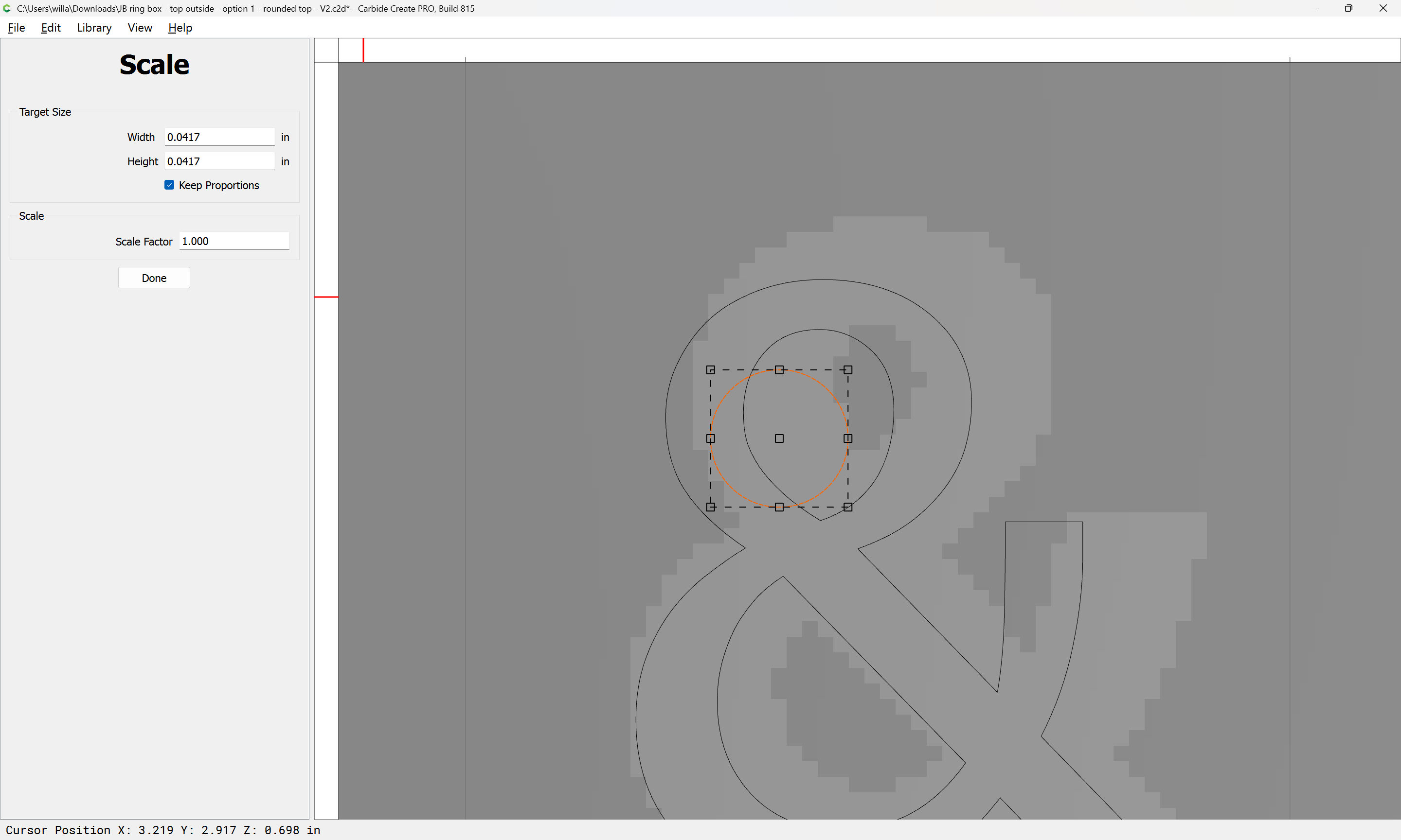
Looks like the smallest part of the lettering, the smallest part of the Ampersand (&) is about 0.035" (0.85mm). You’ll need a tool smaller than that to finish it.
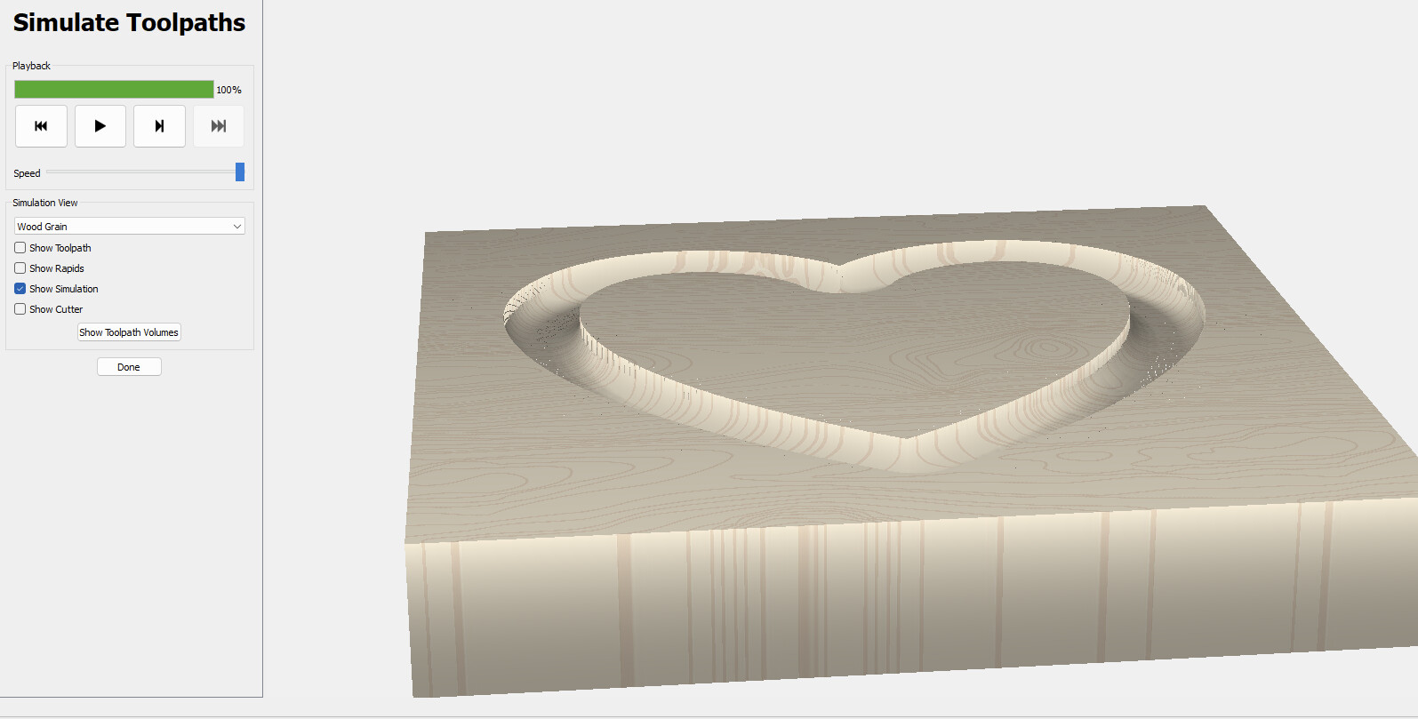
I would remove the text from the model and only cut the dome shape, then cut the text as a 2D operation deep enough to get the lowest letters on the outside edges the depth you want.
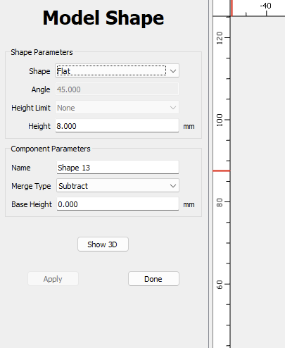
Thanks again Will. I’ve done as you suggested and for the most part it does work now. I increased the size of the text but I can’t seem to get the depth of cut I would like, at least in the toolpath simulation. No matter what height I pick in the window below used for the text, it does not change in the simulation. I will mention that when I view it in the Model 3D it appears quite deep but not on the final simulations. Any thoughts?
You will need a tiny tool which is able to fit into this — you will also need for the tool to have feeds and speeds such that it will not break plunging into the narrow recess.
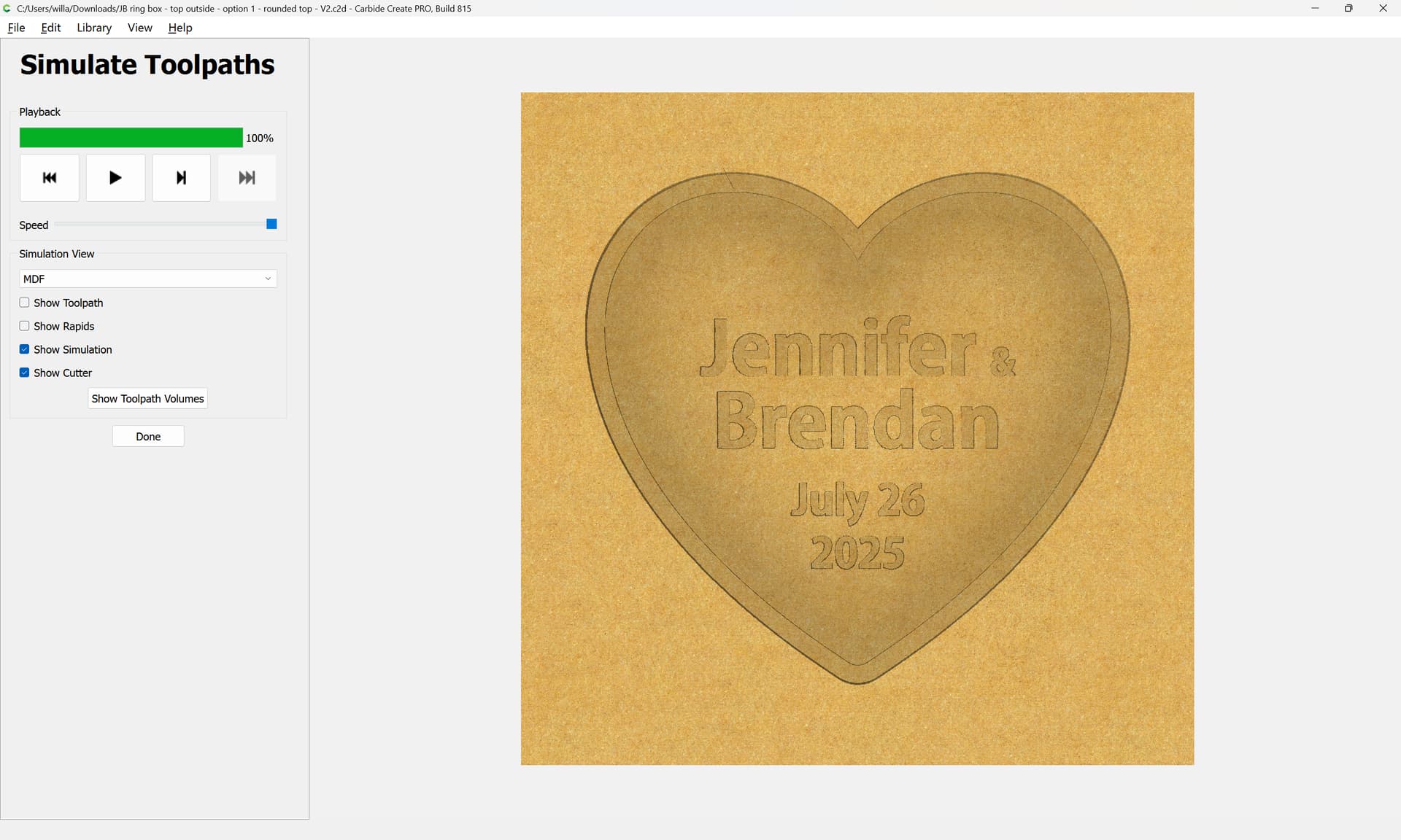
I still couldn’t get the clean text when incorporating it into the model design. I tried what Tod recommended, removed the text from modeling and pocketed the text as a 2D operation using a 1/32 bit. That worked. It doesn’t follow the curve of the heart but it works in a much faster time. Was able to use a larger ballnose bit for the finishing pass.
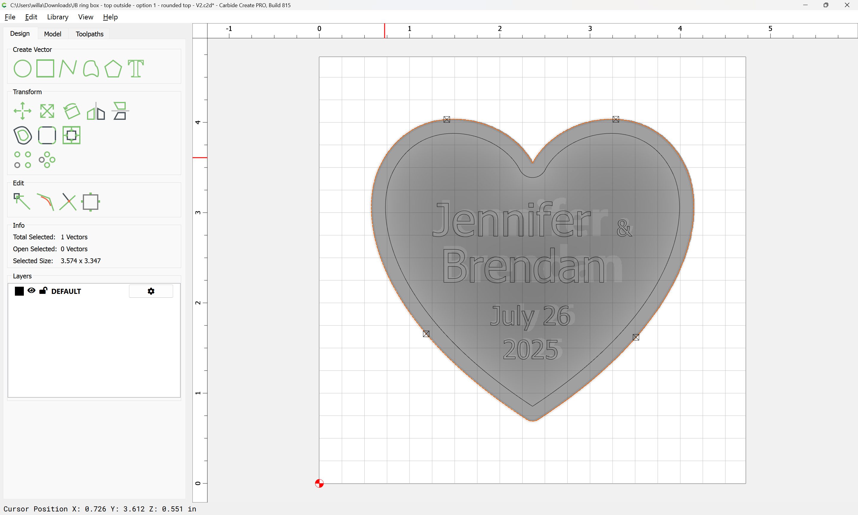
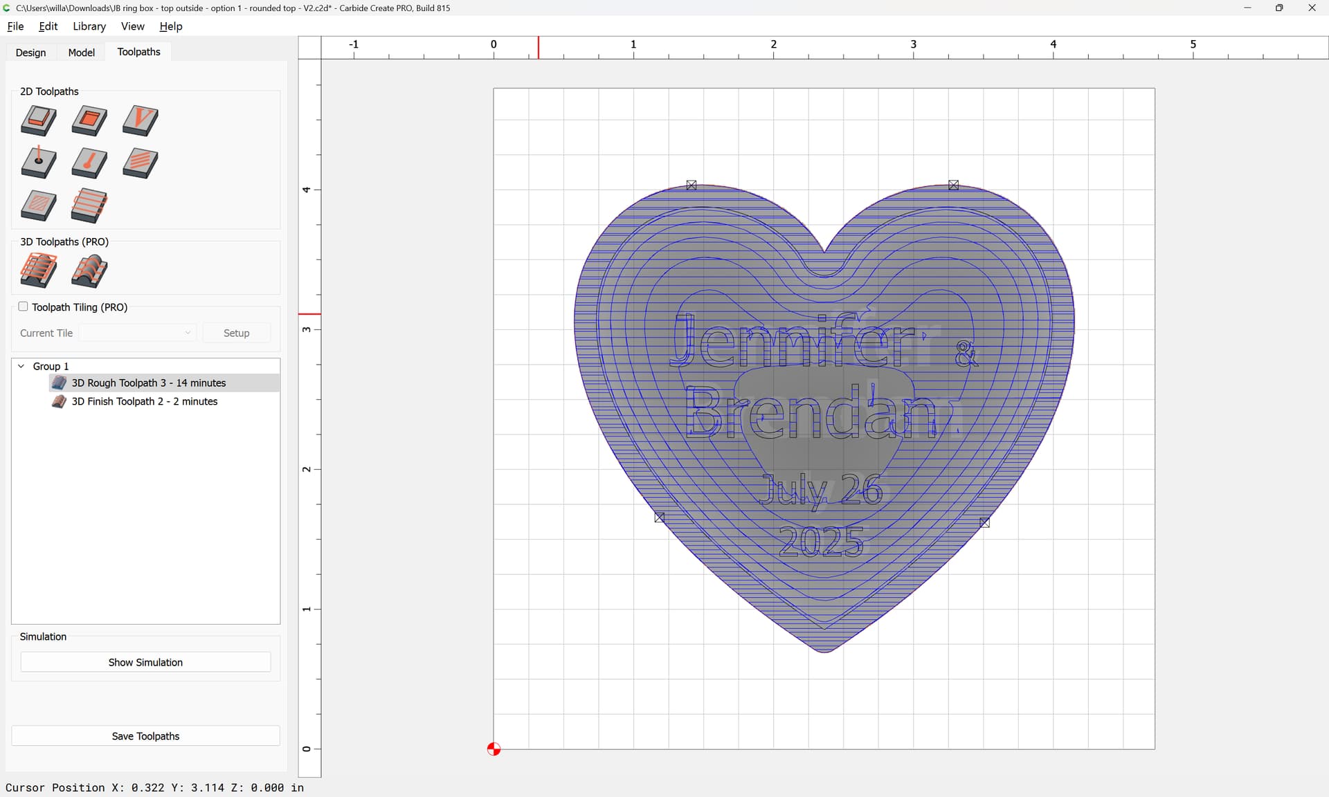
The rough and first finish pass apply to the whole outline. Another finish pass is added for the lettering. To create an outline for this, choose your text model and Create Outline Vectors. (For some reason you had a text outline which did not correspond to the text model.)
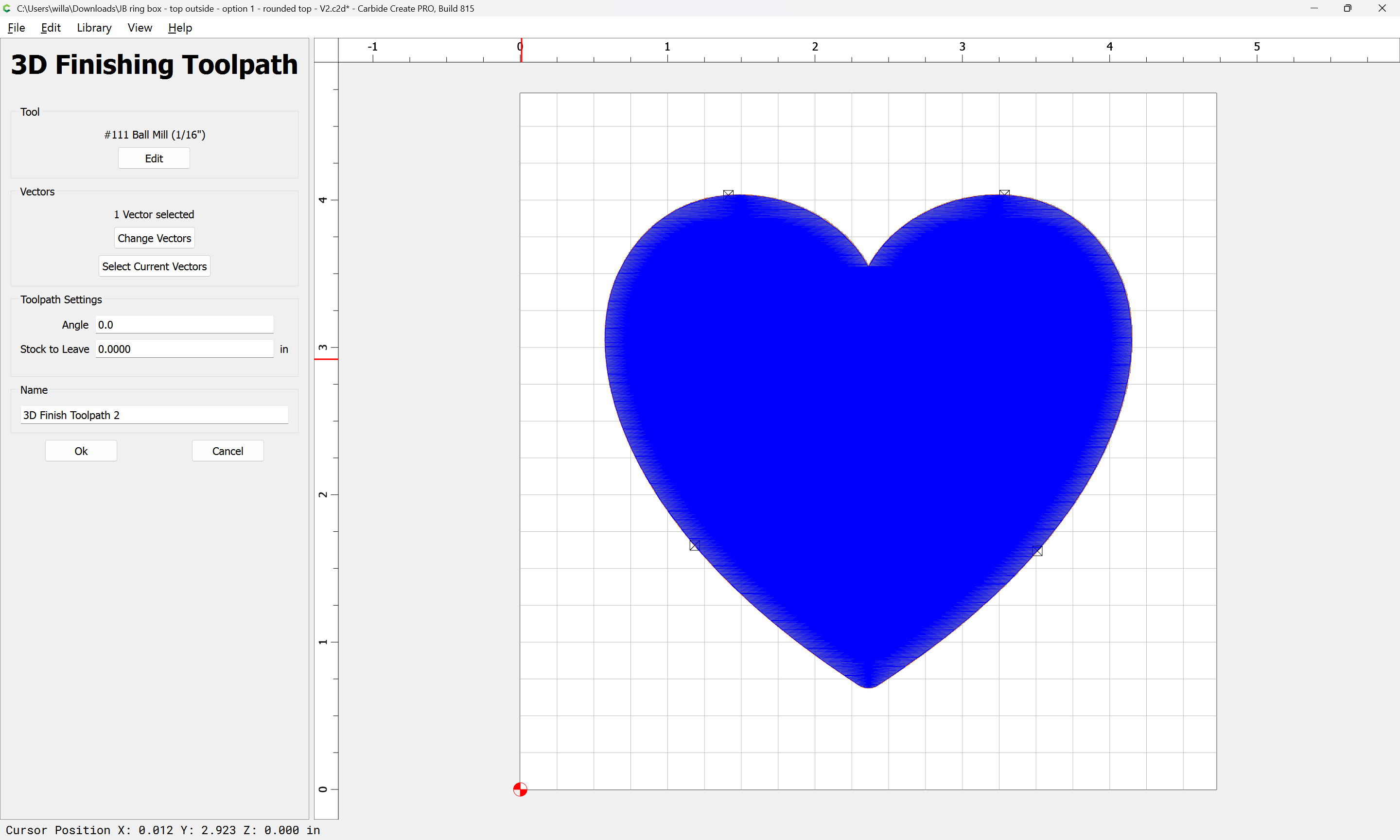
I work in mm, if you’re working inches some substitutions to my bit choices are using a 1/16" for the first finish pass and a 1/32" for second pass on the text. My file shows cutting the outline with a 1/8" bit most of which won’t cut the full 3/4" of your stated material thickness. I’m on a Nomad and only use larger bits when shallow pocketing flat inlay insets.
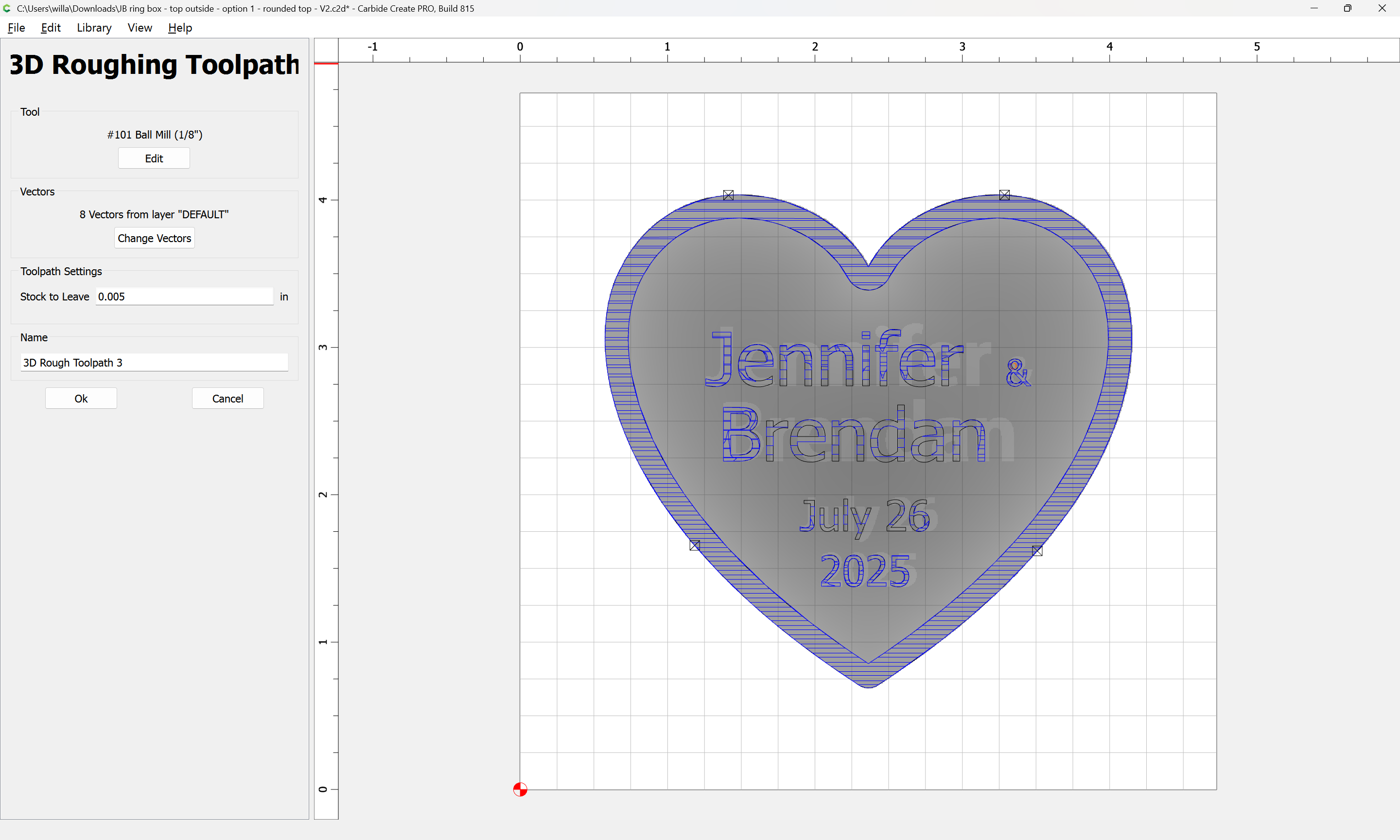
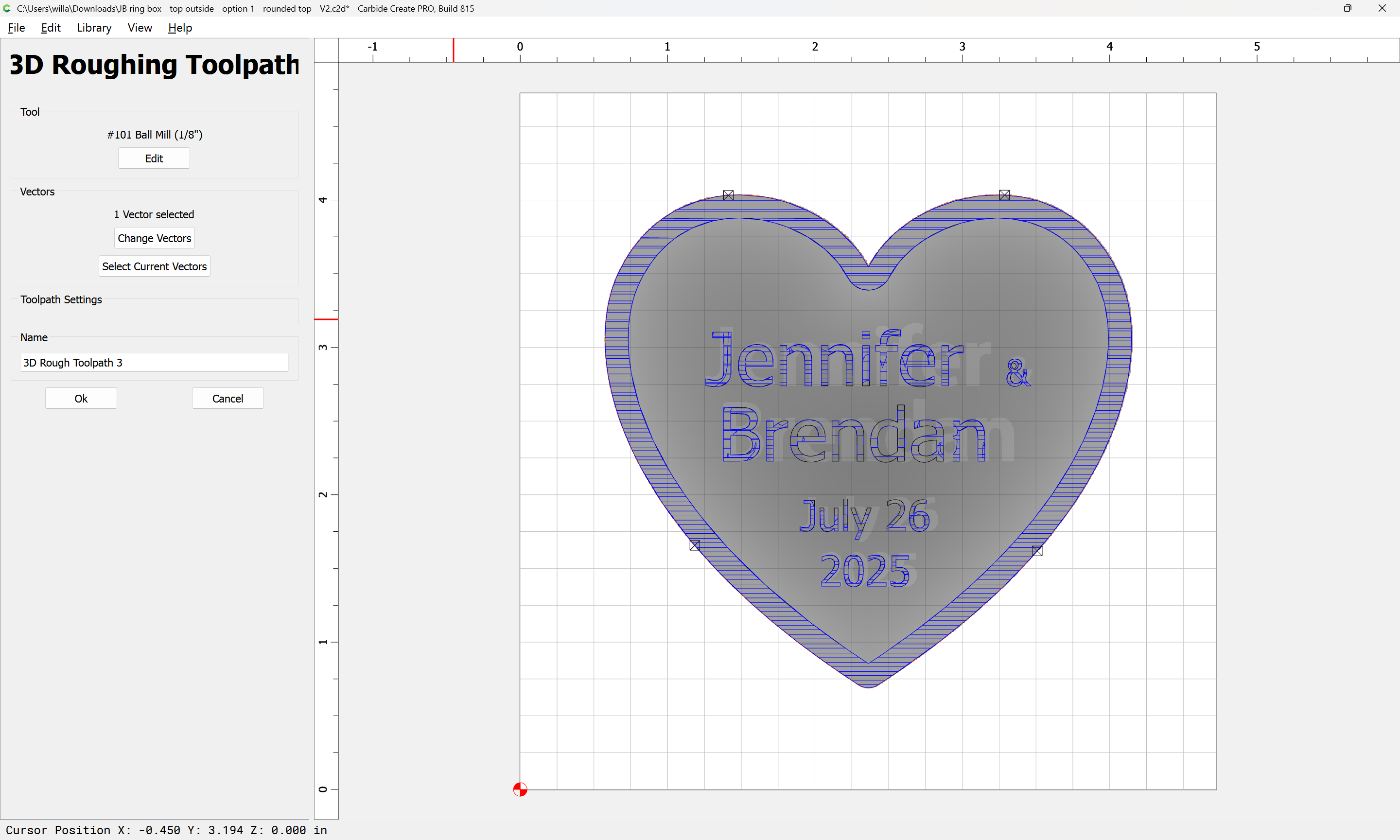
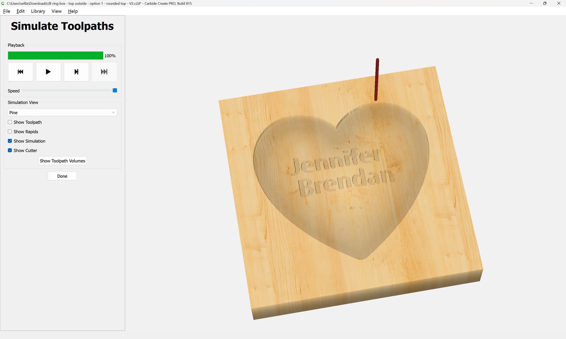
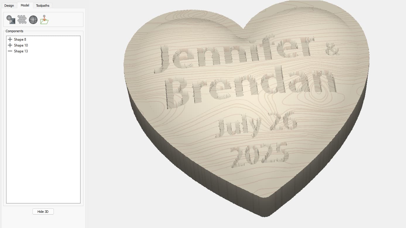
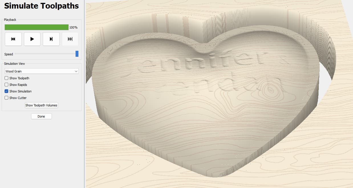
So I’ve gone back to a previous iteration for a couple of reasons but it elicits a big question. The text is done in the Model tab and here is the 3D preview of it.
The text is barely visible. Certainly not the depth it shows in the Model tab preview. I ran the file and the text is as it appears in toolpaths.
Any ideas why I do not get the depths as shown in the Model preview?
Thanks.
Yes. I tried doing a 2D version of the text and used a 1/16 bit then a 1/32 for the Rest machining. No issue going the depth or width of the text. Very curious results, or lack thereof. The current version uses a 1/32 finishing bit as I mentioned.
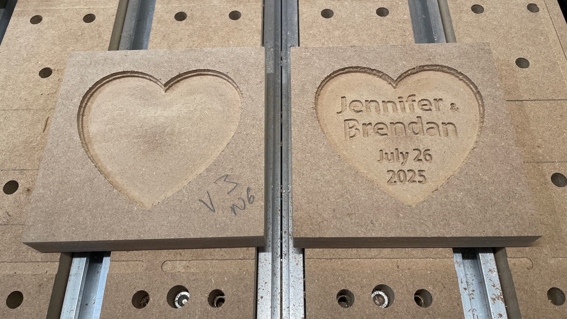
Attached is a photo showing you what I did. I contacted Carbide Support for any thoughts they might have. A number of them helped with one suggestion to reduce the height of the model. Flemming sent me his version of the file which worked, the one change was his use of a straight 1/32 round bit. I took Flemming’s advice and changed the material thickness, then ran the file again but used the tapered bit I had been using. The result was the sample on the left. Nothing had changed. Then it hit me. I made all the changes he suggested including choosing the straight bit, but when it came time to insert the bit, I substituted my tapered bit. Result was the sample on the right.
William pointed out that Carbide Create does not support tapered ball geometry so the 3D preview would not be accurate. Unfortunately, the end result (sample left) was exactly what Carbide preview showed. Somehow, substituting the tapered bit while having picked the straight bit made all the difference.