I am trying to remove the circuit board from the black metal box so I can solder wires onto gdn pin and pwm pin which will support my laser. I removed the 4 small Allen screws .but the circuit board has a long retangle metal piece sandwiched between the black box and the circuit board?? I don’t want to damage the circuit board .but cannot solder unless can remove the circuit board.
Any suggestions
That doesn’t sound right. Can you upload a pic?
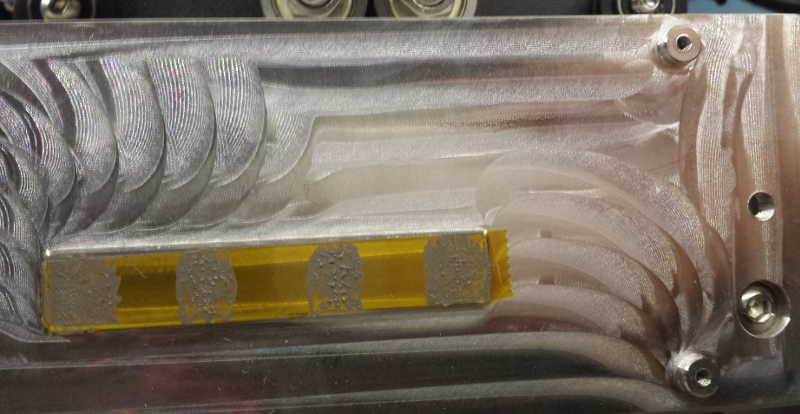
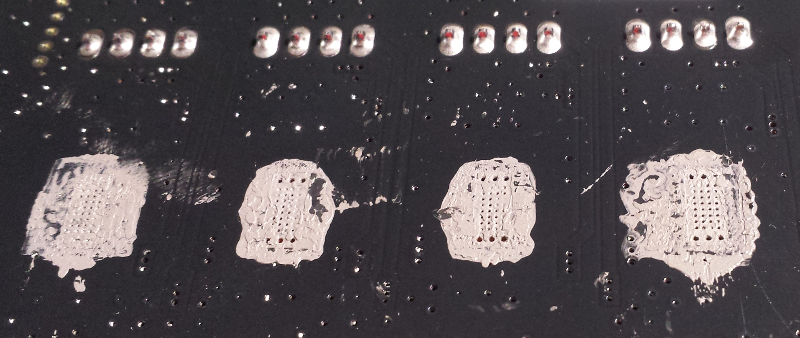
There is actually a narrow strip of aluminum that does protrude from the aluminum plate the board is mounted on. The only thing holding the PC board to the aluminum plate is thermal paste. That strip of aluminum is directly opposite the stepper motor drivers and is for sinking the heat from them away to the aluminum plate.
When I swapped out controller boards, I just applied some force to a corner to put a rotating force on the board instead of pulling on it and it came off easily.
EDIT: I just looked at my spare board. There are four screw holes around that area, but I don’t remember having to take any screws out of the center of the board to replace the board.
EDIT 2: Figured it out. My spare board is V2.1, which has screw holes around the stepper motor drivers. The V2.3 and V2.4 boards do not have the screw holes.
2 Likes
@MadHatter Isn’t the heat sink block between the board and controller PCB and the big heat sink plate attached to the extension? The sheet metal box should come right off.
@Tgh If that’s what you’re seeing, then @MadHatter’s advice is sound…I was confused.
Here is a pic of the large aluminum plate the controller board is mounted to. If you remove the four screws at the corners, there should only be thermal paste holding the board to the aluminum plate.
1 Like
There is no aluminium plate v2.4 circuit board then a long retangle piece of metal glued under circuit board and seems to be glued to black metal protective box.
My instincts tell me to somehow free up the bond between the black metal and the underside of the heat sink.???
I think it’s time to agree with @neilferreri and ask for a pic.
1 Like
I’ve done the same thing (soldering on a connector to access the PWM pin for my spindle drive). I believe my PCB was “stuck” to the plate with some sort of double sided tape.
I was a bit hesitant - but with a bit of gentle plying it popped off without damage - and it seemed to stick back into place once I was finished the mods.
Just go easy - no big nasty screwdrivers prying on things!
1 Like
Where did it release? Between circuit board and heat sink ??
Or heat sink and black metal box
As I recall its fairly easy to remove the black metal box - just a couple of socket head cap screws hold it on. So take that off first.
Then I think there might be a couple more screws holding the thickish aluminum block (heatsink) to the extrusion. Again, going my memory here - but remove the heatsink from the extrusion by whatever holds it there (it might have been the two screws that held the black cover as well.
Once you have the PCB (with the aluminum heat sink attached) free and in your hands, just gently flex the board away from the heatsink.
And keep these parts in a clean environment so the adhesive doesn’t get coated with dust so it can be restuck.
1 Like
Ok @Tgh I understand. Assuming you have the latest enclosure the board is held down with 4 screws, and in addition to these screws there is an aluminium heat sink which is stuck to the rear of the board and the enclosure.
To remove the board, remove the 4 screws then apply low heat to the rear of the enclosure case (hair dryer should work a treat). Gently lever the board up, applying more heat as required. This should release the board.
I did this a couple of weeks ago and it works a treat.
Keep us posted,
Luke
1 Like
Great suggestion Luke, I used a hobby heat gun on black metal enclosure box . With a little persuasion from a thin gasket scrapper I was able to loosen the bond of the double sided tape used to hold that heat sink to the black box.
Installed my 2 pin pwm socked and solder to circuit board . Reassembled and all working .
This forum is so helpfull Thanks again.
Tim
Many thanks ,
2 Likes
@Tgh, I’m glad you got it working, but can you please share a pic? What black box has a heat sink on it. Maybe I have an older version?
As one of the many revisions the latest electronics enclosure has a heat sink attached to it/the board. I’m not sure exactly when the change hit the shelves, approx 3 months ago,
2 Likes