Build 513
I have to uninstall Motion and re install in order for it to plunge cut on initial run.
Used Probe to zero the cutter.
Seems have to re install Motion after shutting down laptop.
any ideas?
becoming annoying
Could you describe the procedure you’re using for setting zero?
4 Likes
Hey, Garth, how about a reply…cause I’m really interested in this odd problem of yours and how to fix it.
He sent me a PM: Here is his reply. I still have some questions:
From 1957 Chebby:
I use the Shapeoko probe to set the X,Y and Z. In the past it has produced great results.
I used that method and ran the file. The machine started. The initial run put the router bit just shy of the material surface. No bite of the material.
I stopped the run and viewed the code. Didn’t understand it and could not see where the Z numbers affected the depth of cut.
Uninstalled Motion.
Reinstalled Motion.
Initialized the machine and set the Corner, and Z dimensions using the “paper thickness” model.
Zero’d all X,Y,and Z.
Loaded the file and began to run it.
Same result. The router bit ran just shy of the material surface. No bite of the bit.
A day earlier I ran the Probe after initializing the machine. Loaded the file.
It ran, but did not plunge into the material. Did a few non biting passes.
Depth of cut was to be 0.760 on material that was 0.730.
The Router finished the run after only reaching a cutting depth of 0.641.
Two days previous I followed my same protocol, and it performed flawlessly.
Build 513 seems to be buggy.
-
Where are you making your CAM? Carbide Create or??
-
Can you attach the file OR a link to it?
-
Is the Probe OFF the edge of the material OR on top of the material?
-
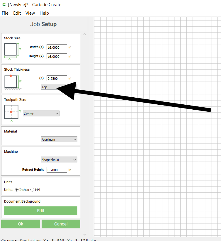
Where are you setting the Z Top or Bottom? (See Photo)
3 Likes
Didn’t mean to waste your time. I had some issues that had to be attended to.
The file is prepared in a CAD program, saved as a dot DXF. Opened in Carbide Create where the
toolpath is prepared.
I use the Shapeoko Probe and it is on the top of the material indexed to the left bottom corner. The Z is set to the bottom of the material.
endplate and bits.c2d (141.3 KB)
In the file you attached it isn’t:
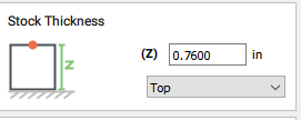
If at any point you did set it to “Bottom” in CC but continued to use the Probe on the top of the material, that would explain your issue (in that situation, CC expects that would actually zero on the bottom, and add the thickness of the material to all Z moves. So if you declare “bottom” but actually zero on top, you end up cutting air)
2 Likes
Thanks Julien,
Changed the stock thickness to “bottom”. No change.
Changed the units to inches. No change
Motion: Zero’d the bit using a piece of paper on the top of the material corner.
No change
Motion: Zero’d all the axis’ and zero’d all offsets. (everything indicated as negative zero, -0.000)
No change
The spindle will manually move to the spoil board.
The toolpaths were created in “Create”
Looking at the file, there are “Z” instruction, at the beginning, and that is for 0.260. I can discern other “Z” instruction.endplates and pockets.nc (59.5 KB)
In frustration I bought Cut 2D Pro. It has a utility that coverts a Cut file to run on “Motion”.
It still behaves the same.
Still cutting air
Uninstalled and reinstalled Motion 5
Final step Rebooted the PC.
Ran the file, Z was 0.700
I am stumped
your NC file only has positive Z, e.g. it’s set for zero at the wasteboard.
if you had it set for zero at the top, all the Z’s would be in negative space
(fwiw http://www.ncviewer.com is a great resource to see what this looks like)
3 Likes
Garth, I don’t see anything wrong with your g-code. Make sure you are setting the zero to resting face of the stock (The bottom of your material / the top of your wasteboard)
If you want to be setting your Z-zero to the top of the stock, you need to change your carbide create file back:
@Garth, sorry if I was unclear before, I meant that your problem was probably because of an inconsistency between where you declared (in CC) the zero reference would be (top or bottom) and where you actually zeroed (which I understand is on top).
Whatever you choose, you MUST zero where you told CC you would, so that the G-code and how you are zeroing are consistent.
First get the probe out of the equation. As @KevinCarr1996 said, reset to “top” in CC, zero on top surface manually with the paper method, does it work then ?
If it works, then add the probe back in the workflow, and make sure to either sit it on the lower left corner with the lip overhanging AND choose the “Probe XYZ”, or if you only want to set Z zero, sit the probe fully on top of the material and “Probe Z” (only) and set X,Y manually.
This is quite important, because if you happen to mix the two (probe position and whether you probe for Z, or for XYZ) you will get wrong results and this can result in the effect you described in your first post, the endmill cutting air 2mm above the surface.
This topic was automatically closed after 30 days. New replies are no longer allowed.