I find the cursor coordinate read out in the design screen very helpful. I would also like to see that same system employed in the simulation screen, so that I can troubleshoot some aspects of my designs that do not show the way that I had expected.
Can you share an example of what you’d be looking to troubleshoot with the coordinates?
In the Vcarve software when you hover over a spot in the simulation view it shows the coordinates. I use that to check depth at spots especially when working on an inlay.
1 Like
Send Rob a screenshot.
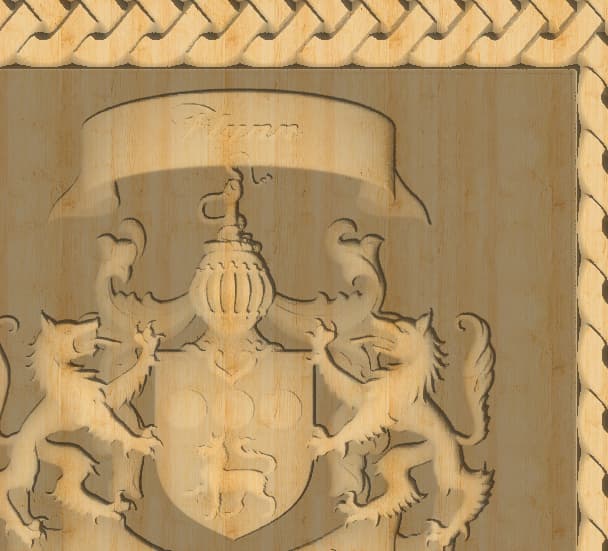
So, for me it is mostly a depth concern. You will notice on this image of a 3d carve from an STL, that the pockets in the neck area of the wolves are different. I’d like to know how deep the pocket areas are so that I can make adjustments with another tool pass.
1 Like
How does the coordinate readout look in context of the visual ?
Do you click or hover ?
So, it sounds like the main use from both of you is to find the depth at a particular point. (Which we already have for the model tab in the 2D view)
We’ll keep that in mind as we tweak other parts of the program to see how we can integrate that.
1 Like
In this screenshot I had my cursor where the red arrow is.
As you move around the coordinate values in the lower right corner are constantly updated.
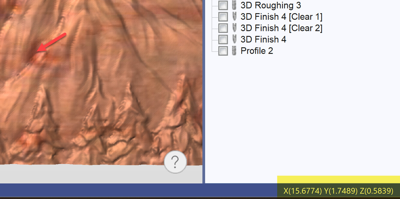
It does the same thing in the 2D view as well.
2 Likes
Thankyou! It will make it a lot easier to find the correct spot and depth than flipping back and forth with the 2D view.
This topic was automatically closed after 30 days. New replies are no longer allowed.