Ideally what I want to do is take my vector file and have my CNC carve this by just “drawing” the lines, but vary the depth according to the value (so maximum depth for black, minimum depth for white). I’m fairly certain Vectric Aspire can do this effortlessly, but I don’t have access to it. I use Fusion 360 for my CAM, and a combination of Fusion and various other softwares for the CAD stuff.
The only thing I can come up with is making a 3D model in Blender, and then just letting the machine cut the 3D model however it sees fit, but it’s not going to give me the nice smooth lines that I want. I just want it to draw a smooth line while moving up and down in the Z-axis. Any ideas?
Edit: Forgot to add - is this something Carbide Create can do? I’ve never used it.
How big is this going to be. Very small lines work best with 15 degree vee bit. A 60 or 90 degree vee bit if this is relatively small will barely scratch the surface. When you vcarve the vcarve bit tries to touch both sides of the line. So when vcarving try to use the bottom of material or the “t” which means bottom of material. If you restrict the depth on a simple vcarve it will not look right. Just be careful when using a 15 degree vee bit with use bottom of material. You can cut quite deep and on a lid of a box you could cut through thin material. So choice of bit is dependent on the size of the object and the thickness of the lines at the size you want to carve. So if the object is 2" a 15 degree would be best but if the object is 12" a larger 60 degree might cut best. Try both types of bits in the tool path and look at the simulation. If you can barely see the simulation then the bit you chose is too big.
I’m sure this is all great info, but you’re WAAAAAAYYYYY ahead of where my issue actually is in the process. Also, I’m probably not going to use a v-bit because I don’t want the line width to very as I vary the depth, but I’ll try a few things.
What I’m asking is how to communicate to the CNC to move in the way that I want it to ie. trace this line, but move up and down in the z-axis as you go, according to how light or dark the line’s value is in that spot. Fusion 360 doesn’t have a way to do this easily, or not one that I can find. I’ll see if I can figure it out in CC.
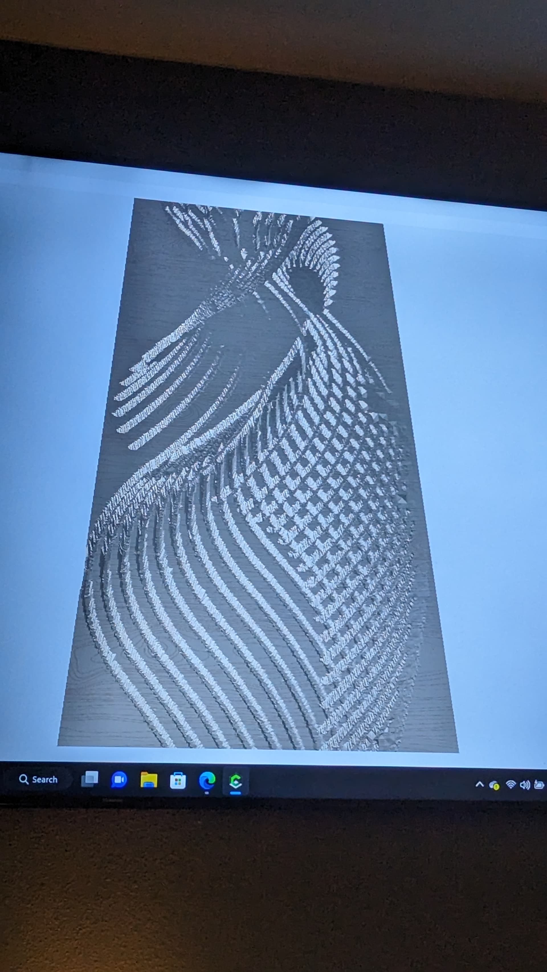
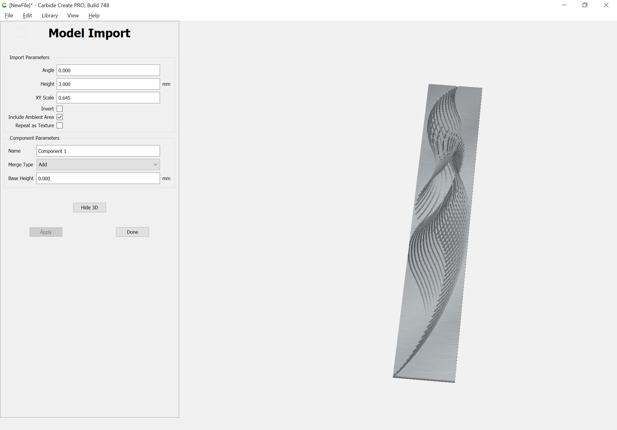
If you have cc pro you can do it in the modeling tab otherwise their is no way in cc that I’m aware of that create the texture your looking for.
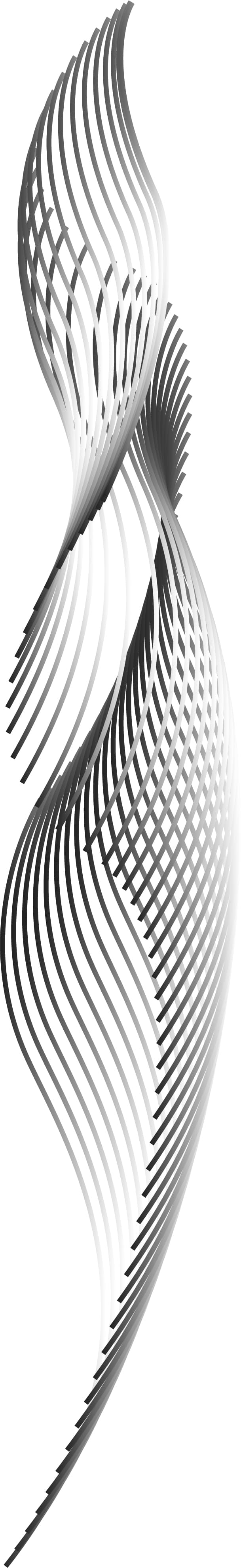
This is still rough I just threw it in the program to see if I could figure out where you meant
Will, I think that’s “half the battle” the way he describes it. CC 3D paths are still going to zig-zag/lace/raster cut the 3D shape. Even if he were to trace the image to get boundary around the lines/swoops, it still won’t follow the lines rather than cut across them.
He want to combine a contour cut (follow part) with the Z variation of 3D. He would need the centerlines of each curve modeled with the variation in Z. And then a CAM algorithm that can follow them.
If there was a way to vary the width of each line based on the greyscale, then he could program it as a V-Carve, but then use a ball mill on the machine. Corners would all have to be round since the V-Carve would want to pick out the sharp corners.
I would try googling “2d image to stl file” https://imagetostl.com/
Once you have an stl file, I’d run it through Fusion360 to convert it from a mesh file to a solid file.
Okay, I definitely feel better about not being about to figure out an easy way to do this. LOL.
I’m glad to see that CC Pro can do this somewhat, but Tod is right that it still wouldn’t be cutting along the lines the way that I want. Also, I’m not buying new software to do this, and there’s no use in me having a 2-week trial when I’m probably going to need to do this more than just this one time.
Here’s my plan b, which has now become plan a, apparently:
-Use the displace modifier in Blender to create a 3D model with the proper depths
-Export that model as an STL and bring it into Fusion, along with a DXF sketch of the image
-Use the ‘project’ 3D toolpath in Fusion to carve along the DXF lines while following the elevation of the STL
This sounds like a simple and effective strategy, and it is, but it requires the 3D model to have a VERY high resolution in order to come out looking smooth, and Fusion really doesn’t like such high resolution models. Also it requires doing finicky little steps in juuuust the right order to make sure that the DXF and STL files are positioned perfectly on top of one another, so it’s easy to think “oh let me just tweak this” and forget that it’s going to mess up the whole chain of events. So it’s doable, and I’m preeeeeetty sure it’ll work the way I want, but it’s annoying.
The other option, which I came up with last night while not being able to sleep because who in the heck can sleep when they’ve got a PROBLEM TO SOLVE???, is to just create a simple wave/ripple texture in Fusion, and then use the project command to carve the shape onto the wave. I’ll see if it looks better or worse having the texture actually carved into the whole piece and then carve the lines on top, vs having the wave only exist inside the lines and the surrounding wood to be flat, if you get what I mean. That might end up being what I do just because it’s so much quicker and easier.
Thanks for all the input, everyone. If I end up with something cool, I’ll try to remember to update.
I don’t understand. I already have my sketch, I don’t need to create it in Fusion, and the ‘Project’ toolpath doesn’t care about the height of the sketch plan as far as I’m aware. Am I missing something?