Recently got tired of low use tools taking space in my primary boxes, with the associated risk of damage when rooting around for other tools. So, I started making more cases.
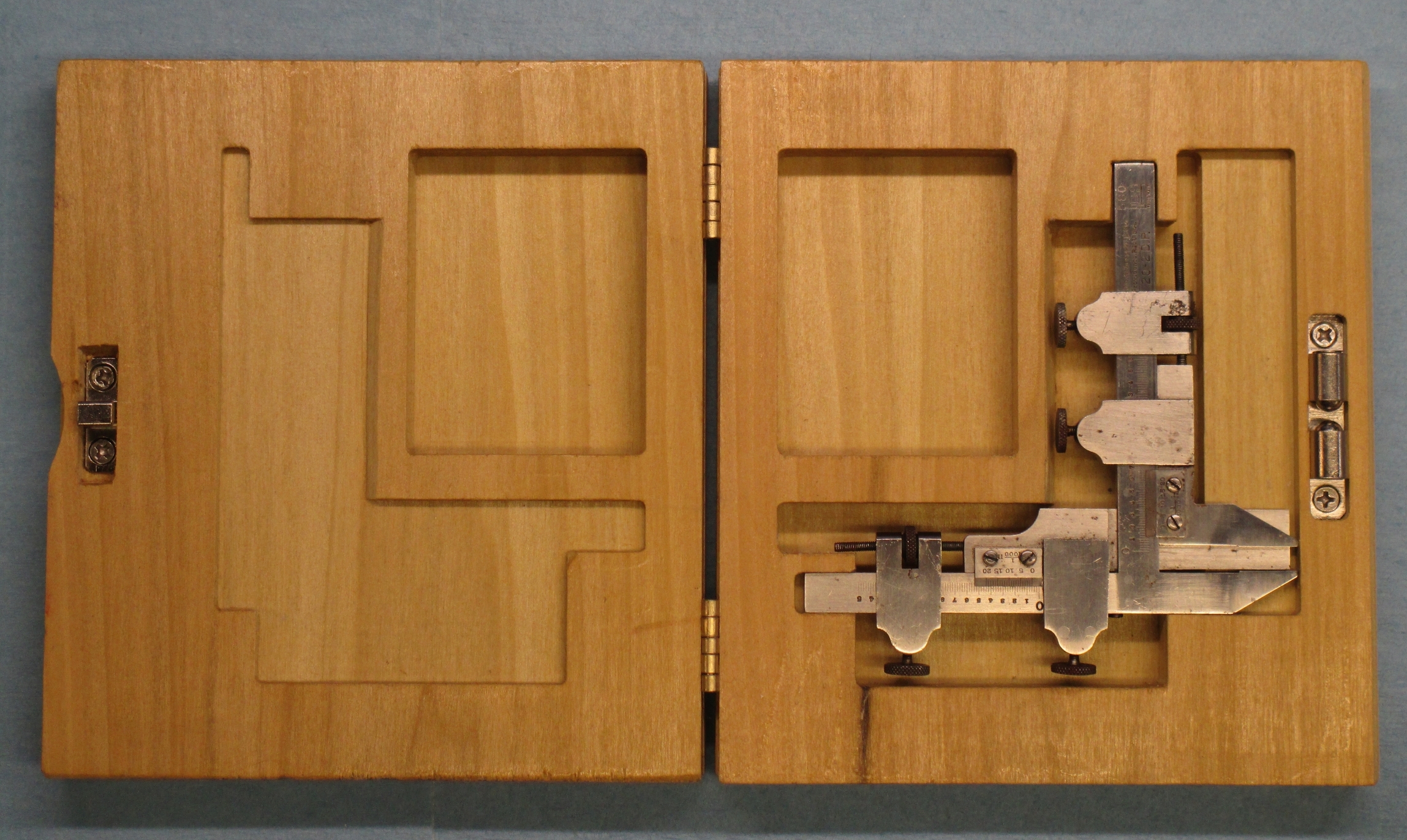
This is a gear tooth caliper. It is for measuring gear tooth thickness at the pitch line, but can also be used for a variety of other tasks, such as measuring tapers, Acme threads, and so on. Pretty much anything in its range where an outside measure is needed at a specified depth from a feature. I use it a few time a year, often in the field, and, as a replacement of comparable quality a several hundred dollars, I figured a case would be good.
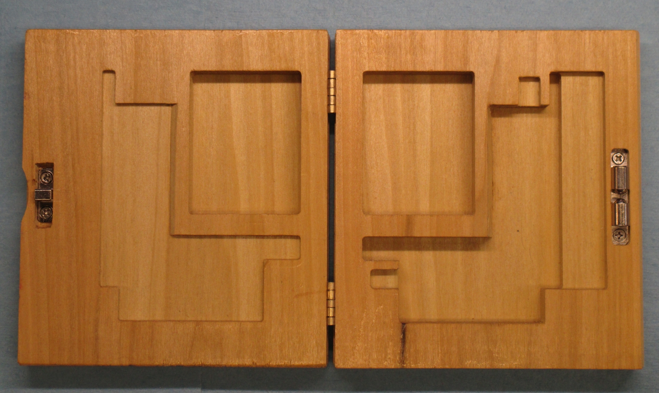
The model was built in Inventor, first as a model of the tool, then using that model to cut a void from a solid block, splitting the block (for top and bottom), making a set of rectilinear bounding boxes for the various cut levels, and projecting these to the appropriate surfaces left by the good model of the tool. First run was close, a little work with a chisel to fix a few things (and fix the model to match) and I didn’t bother re-running it, as it is fine with hand work.
The material is Poplar. This is a fairly soft, very porous wood. Prior to machining, I soaked the blanks from one end with dewaxed shellac until it came out the other end, then let it dry. This gave a bit more structure to the material, made the machined finish a bit nicer, and made finishing easier, as the wood was already mostly sealed.
First, we have the assembled case. The hinges are generic from the orange place. I bought about 20 packs a few years ago of the 3/4" when they were on the discount rack. The closure is from McMaster, and is a pretty common style today. The holes for the closure were piloted during the primary machining to insure alignment.
With the tool in place
And the top.

The lettering was done with a 90 degree, 1.5mm dia cutter. The design was on the inventor model, and I extruded the lettering into the surface and the CAM operation was “engrave”. This combo does a nice job, but the majority of fonts won’t work with emboss or extrude. No clue why, and Autodesk has no meaningful answer (“the font isn’t properly modeled”. Gee. Thanks. Tell me how to fix it…)
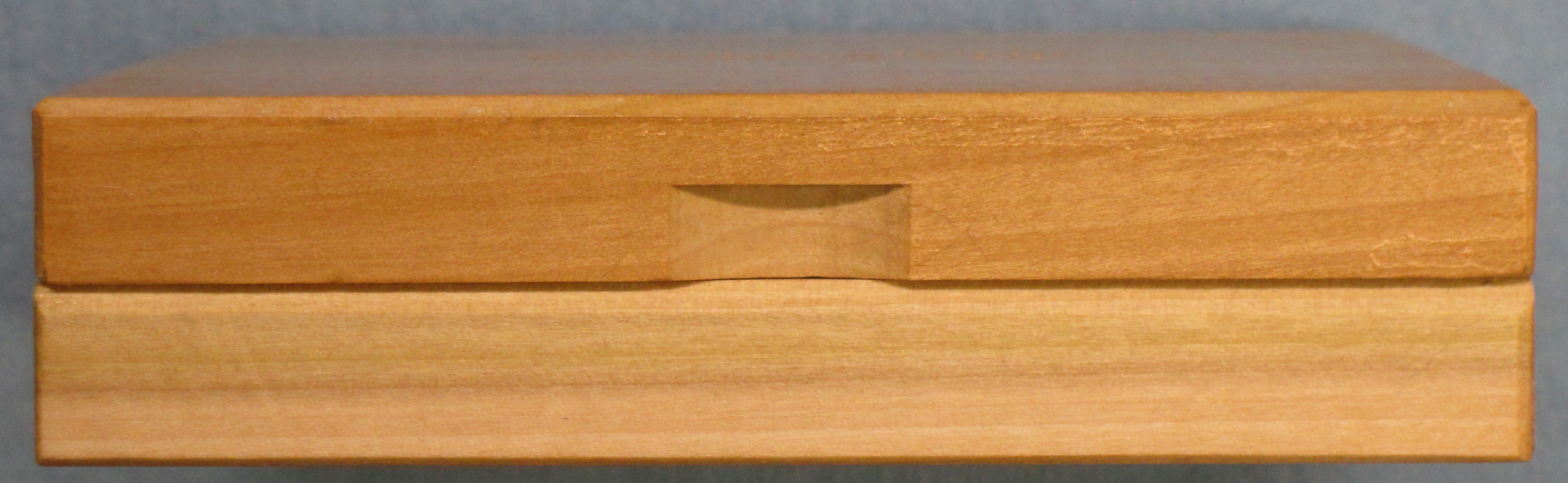
The finger grip for opening the case:
and how the hinges were set:
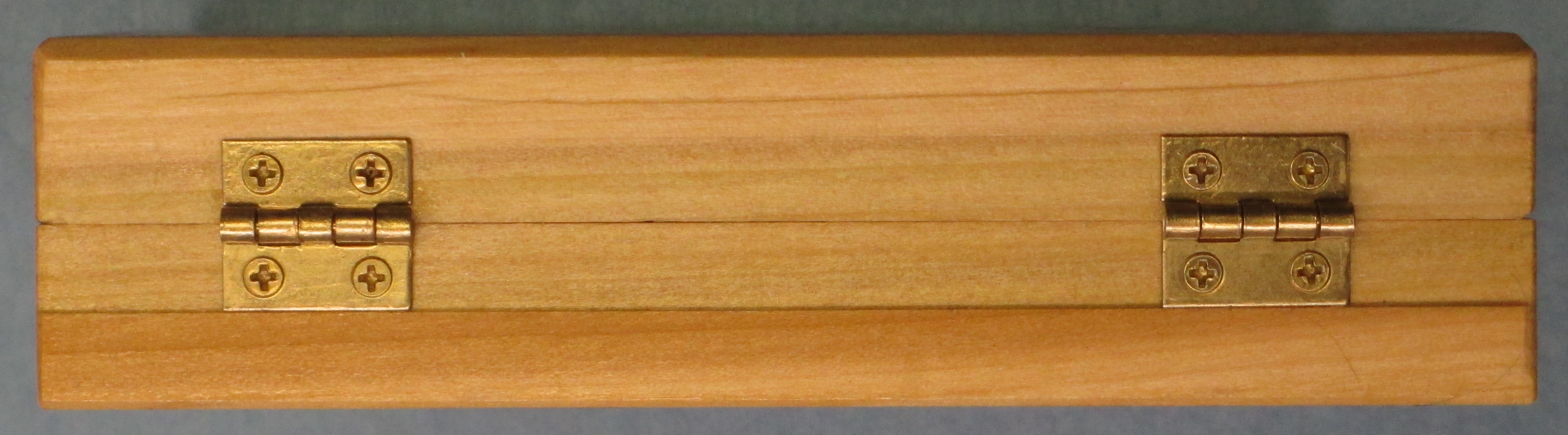
The hinges were set by placing a lip (rabbet, rebate) for the backs to seat to. This was milled at the same time as the interior, in one setup, and was on the registration edge for fixtureing, so no other cutting was needed on this edge. The outside profile was also done then. Mounting of the hinges was done by mounting the closure parts first to set the alignment, clamping the halves together in alignment, placing the hinges the same distance from the ends, center punching with a transfer punch in each screw hole, then piloting. While the parts were clamped, a few shots with a handplane took off the material on the edges where holding was done.
Final chamfering was done with a block plane, followed by sanding (220 and 400 grit), dewaxed shellac to reseal, final light sanding (800 grit), and shooting on a couple coats clear lacquer. Got a little orange peel in the lacquer because I rushed it (too wet). Its fine.
Edit: I didn’t put shots of the process building hte model, as I didn’t screenshot any of it.