I just finished this project, within which I made use of two key features of CC Pro: STL Importing and Tiling. This was a long project with fairly critical tolerances and a lot of complex curves, so, I had to develop/learn a number of techniques to get the results I needed. I thought I would share a couple of them with you folks.
NOTE: My way may not be the best way — it’s what worked for me. If you know of a better method, please tell me - or I will be forced to repeat my mistakes sometime down the road. But I’m sharing what did work for me on this project.
This is really long…but I hope you find it useful:
TILING
First, the most accurate registration technique for Tiling I could come up with:
I played with a number of registration keying strategies, lines, etc. and the most accurate technique turned out to be the simplest method possible. It’s a little time-consuming, but it’s dead-on each time:
It starts with an accurate left-side fence…that runs the entire length of your bed. Cut it with the gantry, so you know it’s dead accurate to the Y axis.
Then, the key is to lay out an extra piece of geometry in a waste area, exactly the tiling distance from zero - and drill a hole using any bit (I always used the first bit of the toolpaths) and a Drill Toolpath.
For example:
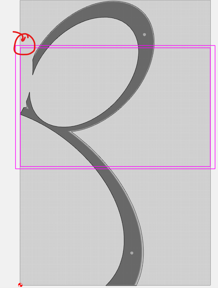
Given a geometry larger than the bed of my XXL (that has complex curves and plenty of them):
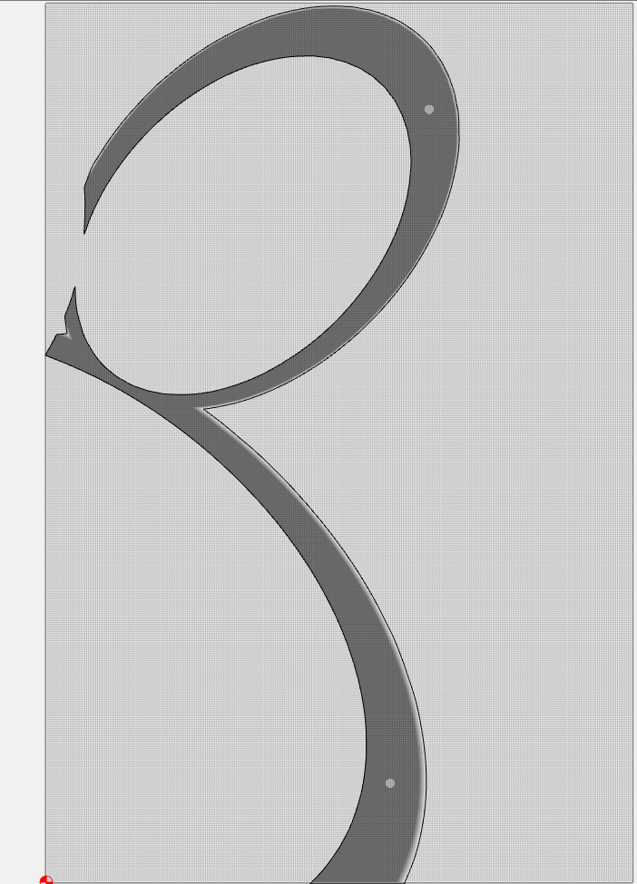
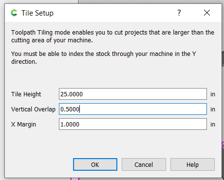
Now…do a set up of the tiling. Select a tile length that will allow you to place geometry in a waste area. For this example, I can choose 25"
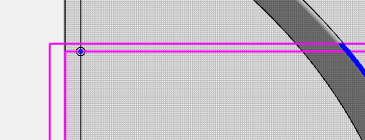
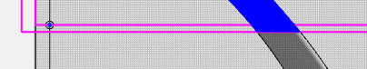
Which creates “Tile Zeros” where there is no other geometry - Here:
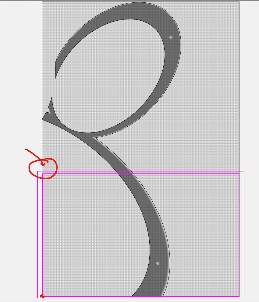
and Here:
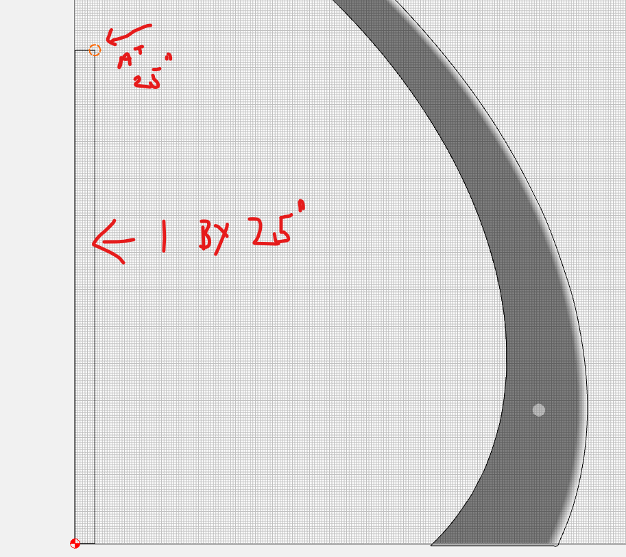
Now…just measure up 25 inches (my Tile length) and put a circle centered on the 25" mark
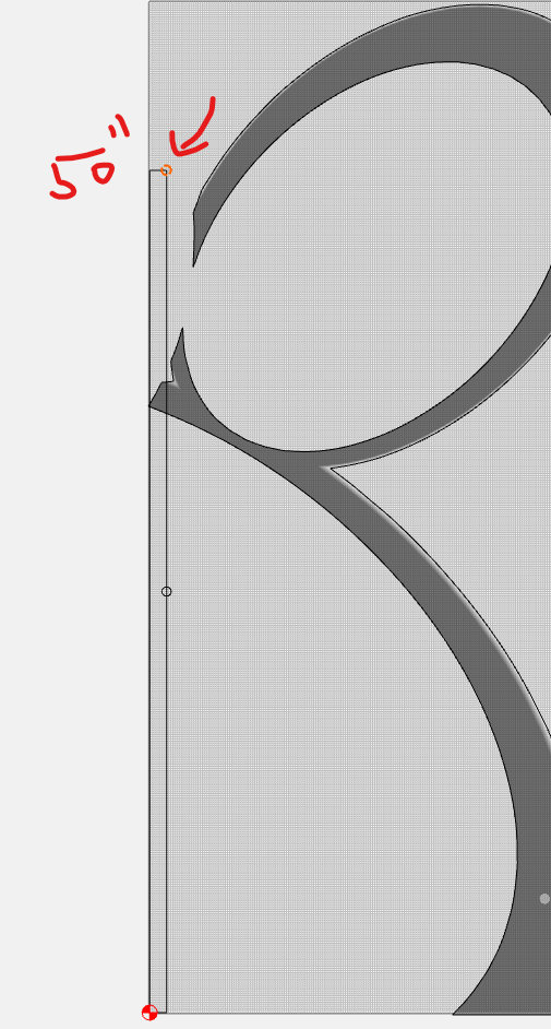
Do the same at the 50" mark (if you have 3 tiles):
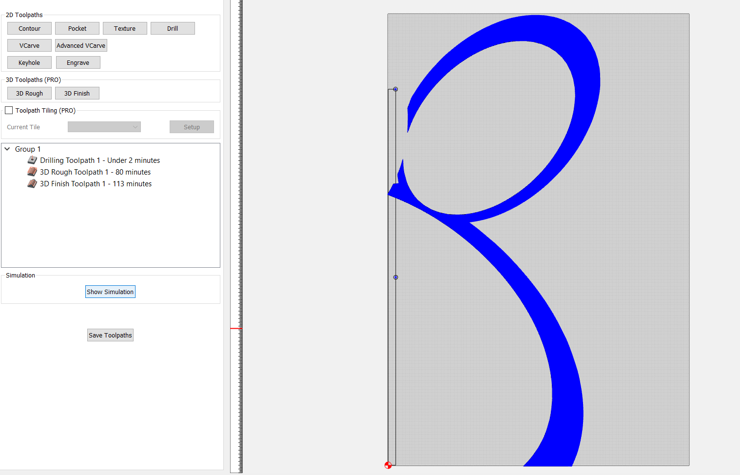
So…now we’re ready to make toolpaths. Just put a drill toolpath as the FIRST toolpath in your job for the two circles:
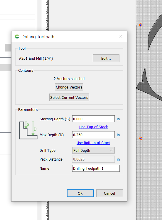
Then, do the rest of your toolpath work for the design:
Now…when you Tile your toolpaths, you’ll notice that the circle will always be cut first. And here’s the important part - because the drill toolpath is within the OVERLAP area of the Tiling Setup, it will be cut, in its entirety, for the the first tile…AND it will ALSO be cut (again) when the second tile is cut.
Tile #1:
Tile #2:
So…Cut Tile 1 - the hole is created…then, the rest of the toolpaths will be cut.
Then, move the piece, so that the hole is aligned with the Zero of your table…approximately - it doesn’t have to be exactly at zero…but it does have to ride the fence perfectly.
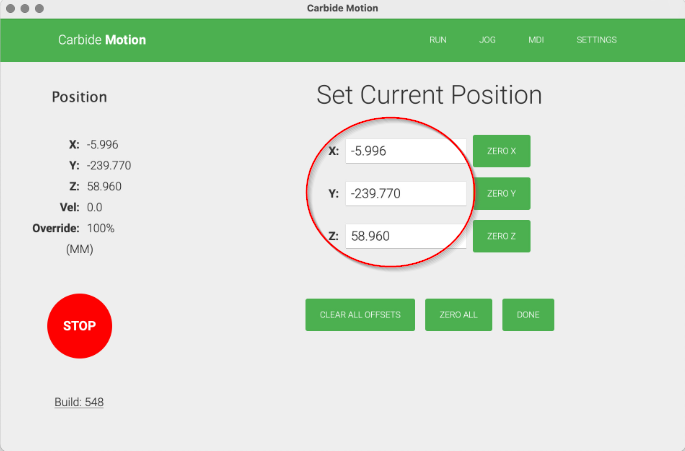
Now…here’s the trick: When you cut Tile 2, the job is going to try to recut the hole first. I pause the job as soon as the spindle starts to drop towards the hole, and STOP the job. Then, I go to JOG and drop the bit down from that location until it gets close to the hole. Then I start to jog around until it fits the hole, keeping track of the distance and direction of X and Y, thatI need to move the bit until it sits directly in the hole. Then I raise the bit, jog to zero, and adjust the spindle location by that same distance and direction and REZERO. Then I restart the job and let it go. It descends into the hole (very satisfying and reassuring when it does that) - and then goes on to perfectly continue all of the rest of the toolpaths.
It’s an extra step - but I have NEVER had the bit come down in the hole accurately…no matter how precise I try to be in relocation - even with physical keys and lines and all sorts of things. Turns out, the simplest thing - a hole the size of the bit - is the perfect alignment aid…and spending a few minutes getting things aligned and rezero’d is perfect for making sure lines continue correctly after tiling.
2-Sided (3D) STL-Imports
This project required two-sided machining…because some of the 3D STL files had bevels on one side and cove cuts on the other.
To Facilitate this on CC Pro took some doing…because you can’t undercut on the Shapeokos…so you need to cut (and reference) both sides of the design in two jobs (one per side).
Here’s how I did it:
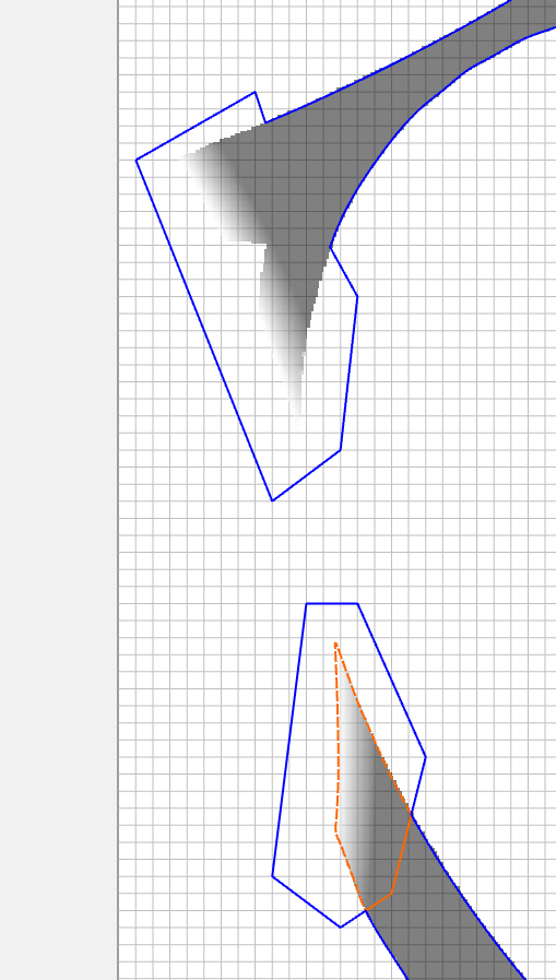
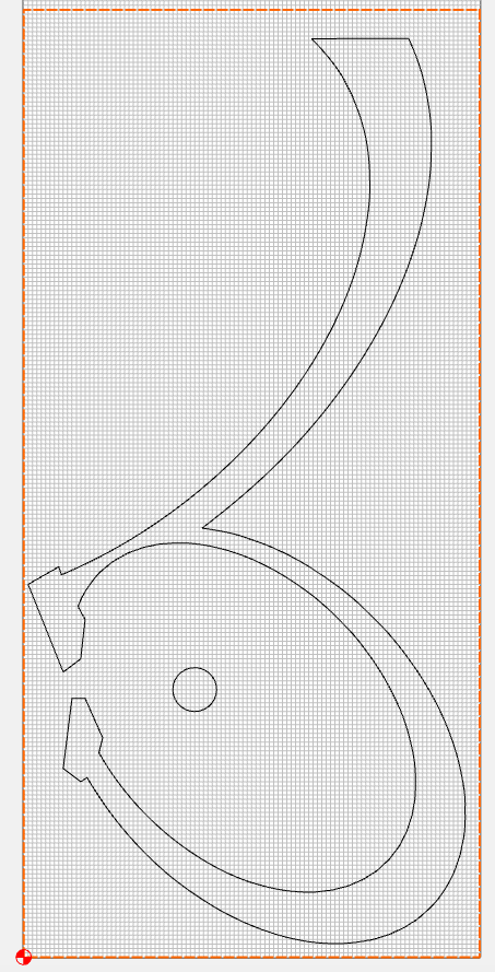
I started by importing the TOP side of the STL file:
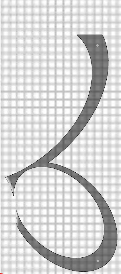
In this case, those white spaces on the tips of the forked sections are COPES. In order for the cope to be cut all the way through the wood, and to minimize the cutting time, I found the need to add some geometry to increase the deadspace for the cut…beyond the width of my cutter…so I added geometry to the tails (the only place it was going to be cut…You’ll see what I did when the cutting was throughout the design in a second). So I added geometry to the tails and Boolean WELDED the shapes to create a new shape:
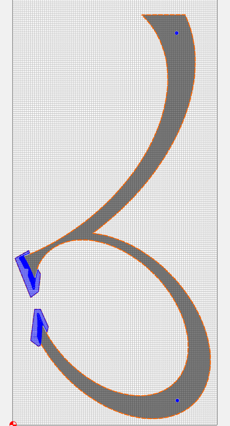
Then I modeled the resulting geometry:
Now…I’m going to need to flip this over and cut the bevel side of that same STL file…so I need to do a few things:
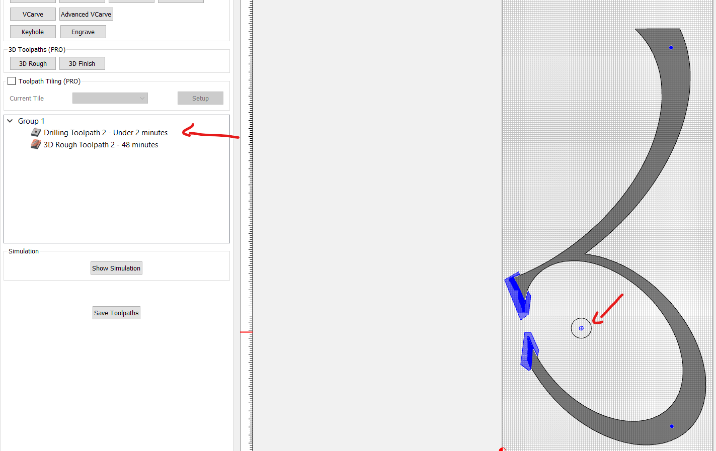
First, I need a reference point. So I draw a circle somewhere on a waste area on the piece and then add a toolpath for that circle that drills ALL THE WAY THROUGH the piece. I make that Toolpath THE FIRST toolpath in the job:
SAVE that c2D as the TOP Side
Now you’re ready to work on the flip side…the BOTTOM of the STL:
Start by deleting ONLY the model of the imported file - LEAVE THE OUTLINE.
Then… add a rectangle, the full size of my stock (the actual stock…not just the size of the bed). This does not have to be precise, but the closer you get, the better you’ll be. Align it to your bottom left corner:
Select the rectangle, your imported STL traced outline, AND THE CIRCLE. GROUP them as a single unit, and then MIRROR HORIZONTALLY. Then UNGROUP THEM.
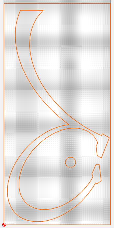
Now…import the STL again…this time, using the BOTTOM perspective:
NOTE: You will need to ROTATE the imported file 180 degrees so that it orients like the flipped image you already have:
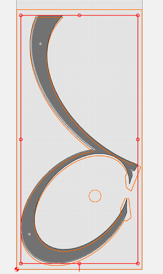
Now…nudge the new model until it snugs in perfectly with the outline. Accept the import. And you can delete the old outline.
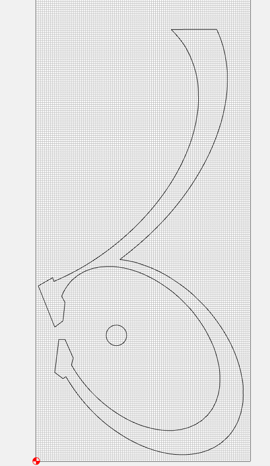
Now you’re ready to set up the toolpaths for the new layer. I have found that, to get the full cut of the bevels, all the way through the stock, you need to create an offset to the traced STL file wide enough for the bit that you’re roughing with…so I put an OUTSIDE OFFSET and that’s what I use for my rough and finish:
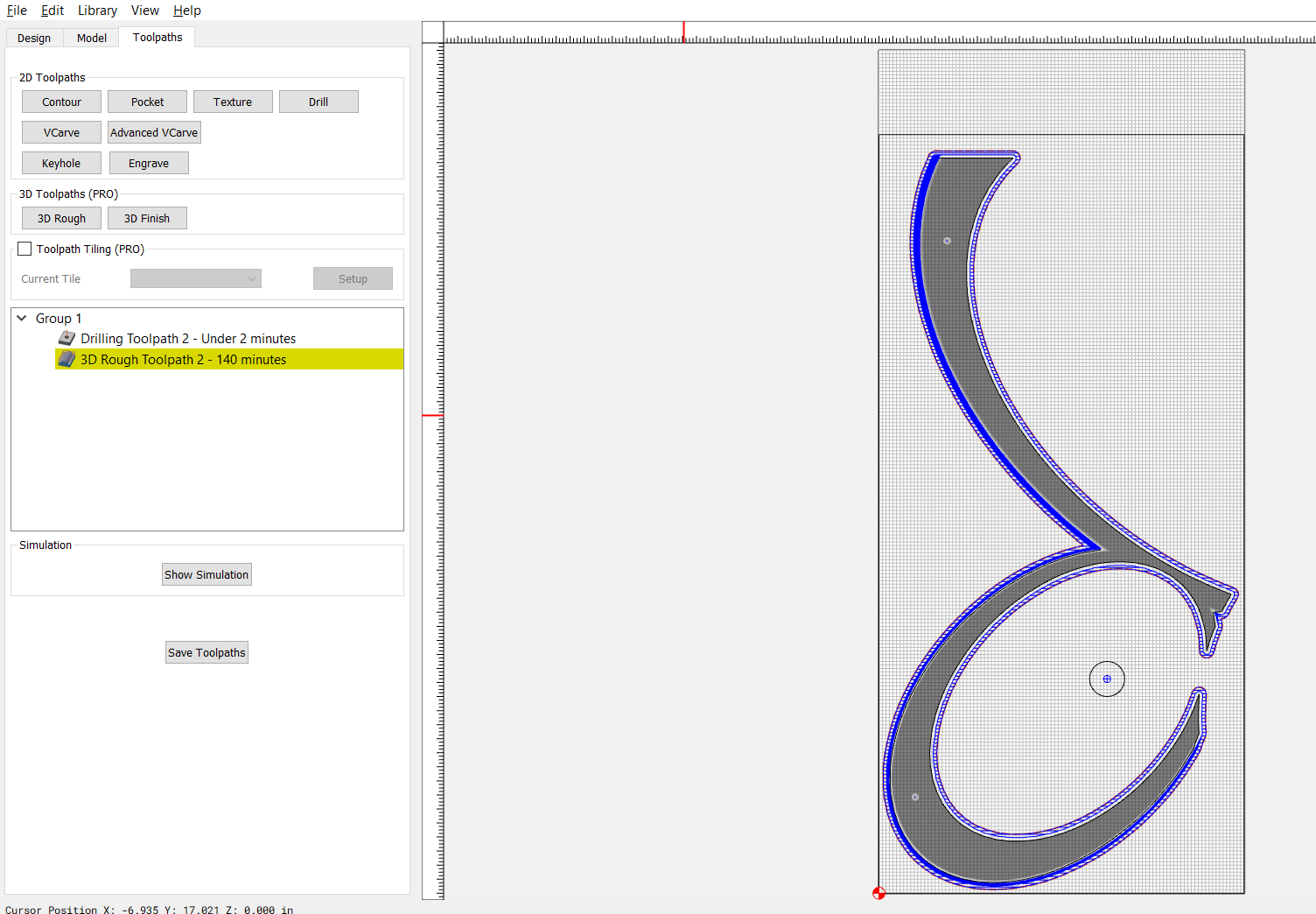
NOTE that the circle toolpath is STILL #1…only the circle is now in it’s flipped location - and correctly aligned to the newly imported file.
Save the BOTTOM c2d
OK…now to the cutting:
Cut your TOP c2d…the circle will cut through the board first, followed by whatever else cuts.
THEN FLIP THE BOARD SIDE FOR SIDE
Now load the BOTTOM c2d
Start the job…it will move to the circle location and begin to plunge to drill the hole (again). STOP the job in place. Then, just like the technique for Tiling, lower the bit and jog until it aligns directly into the hole — keeping track of direction and distance you need to adjust. Then raise the bit, go to current zero, move the spindle by the exact direction and distance you just used, and rezero. Then start the job.
VOILA…it will cut precisely in the right place (as long as your fence is straight and your stock sides are parallel).
Long enough of a post?
Hope this helps someone somwhere…
- Gary