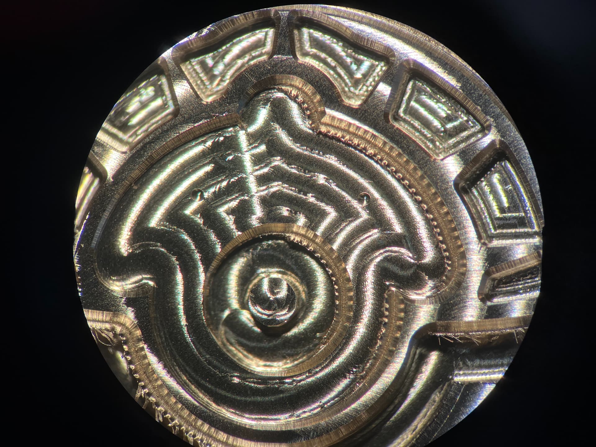
Hello! I am a watchmaker in Lancaster PA and I am using my Nomad 3 to make several parts for a watch I am in the process of producing. The parts are milling quite nicely, but when I run a chamfer mill on the edges, it is consistently misaligned. Off by about .2-.3mm. I understand that the chamfer might be uneven on various shapes, depending on the size of the endmill used and contour of the shape, but the chamfer is even off on circles. The workpiece is very secure on the table with no movement. It is one continual run and everything else appears to line up correctly(the chamfers are cut in the middle of the run). I will attach a picture so you can see the issue. Thank you for your help!
1 Like
that is odd, have you checked the runout on the chamfer tool, and/or collet?
1 Like
As you likely already know the champfer bit is not supported. So likely you are making the plunge the full depth to get the champfer. If that is the case is your champfer bit actually the size you think it is. My understanding for doing a champfer is you do a contour with no offset so the bit goes down the center of the line. If you bit is supposed to be .375" and it is .370 or .380 in reality then the bit will be off. You would think that it would go down the center but when you set the tool up as .375 the tool path tries to take half of .375 and if your bit is not really .375 you will be off.
One other thing could be you need to calibrate. There are instructional videos on the forum to help you calibrate. Basically you cut some shapes of known sizes and then measure them. If they are consistently off then you would make gbrl adjustments to the stepper motors. If however the shapes are inconsistently off then you likely have a mechanical problem.
So measure your bit and change it in your custom tool settings if necessary. Try a calibration to see if you are cutting accurately and adjust as necessary.
Thanks for the input Ryan. I am pretty new to CNC’ing, so I research that and check it this weekend!
Hi Guy! Thank you for taking the time to leave a message. I put the chamfer bit under the “vee” classification. This seems to work well for other applications. I can step it down in the same way as other bits. Also, I originally tried to chamfer without offsetting the line, but if the chamfer is off in the slightest, it leaves a groove on the edge.
I can run some calibrations, but what doesn’t make sense to me is that I am basically just running the same path, in the same run, with different tools and they aren’t lining up. It does’t seem make sense to me that a calibration would effect this,(unless different bits are calibrated separately) but I will look into it.
Thanks again!
Is the chamfer geometry the same as the geometry of a V endmill?
Any chance you moved the spindle/gantry while changing the bit?
1 Like
as far as i know, it would be next to impossible to do that on a nomad. the nomad 3 uses ballscrews.
Yes it is. I think they are pretty much same thing.
It continues to do the same thing repeatedly and I am very careful when I change the bits, so I am guessing no movement there.
Please post:
- specifics of the chamfer tool
- screen grab of your tool settings
- .c2d file
- step-by-step notes on how you are securing your stock and setting zero relative to it
- photo showing a part still in place on the machine
if you are re-zeroing with a probe (x and y) and use different diameter end mills, make sure the probing is using the correct bit diameters.
1 Like
This topic was automatically closed 30 days after the last reply. New replies are no longer allowed.