Chamfer perimeter

Do you have a Fusion model? You could run a trace toolpath.

Thank you Stephen, Will and Neil…

I use MOI3D to model, then export to Illustrator where I save the file as an .svg. I have now created an additional path 0.8mm away from the perimeter (based on Stephen’s method). Would this work?

31

C3D%20Chamfer1

If you use a 0.08" offset, the depth of cut for your vbit will have to be 0.08 before the bit touches the corner of your material (presuming you’re using a 45° vbit). Add to the depth of cut what ever amount you want to chamfer. I usually go with 0.05" to just break the edge but you may want more. Just be careful you don’t exceed the cutting height of your vbit. I usually use a 0.03" offset, as I often use a 1/4" 90 deg vbit with a cutting height of 0.125, so with an 0.08 DOC I’m cutting right in the middle of the edge.

Thanks for this Stephen. I actually haven’t got my chamfer bit yet. Which would you recommend a vbit or a 2 flute chamfer end mill?

Yes, that should work.

You’d need to do the math (or just draw things up) to determine how wide the expanded stroke would need to be to get the desired chamfer. The specifics would depend on which application you’re using.

To get the desired 1.5mm chamfer we start by drawing a 1.5mm circle on the point:

Then we draw in a circle from the end of the line to a point on the circle:

Which gives us the desired dimension of a diameter of 2.6903mm

We select the lines which make up the chamfer and expand that stroke by that dimension with a rounded cap:

to arrive at:

Stitch everything else together and export as an SVG to import into Carbide Create:

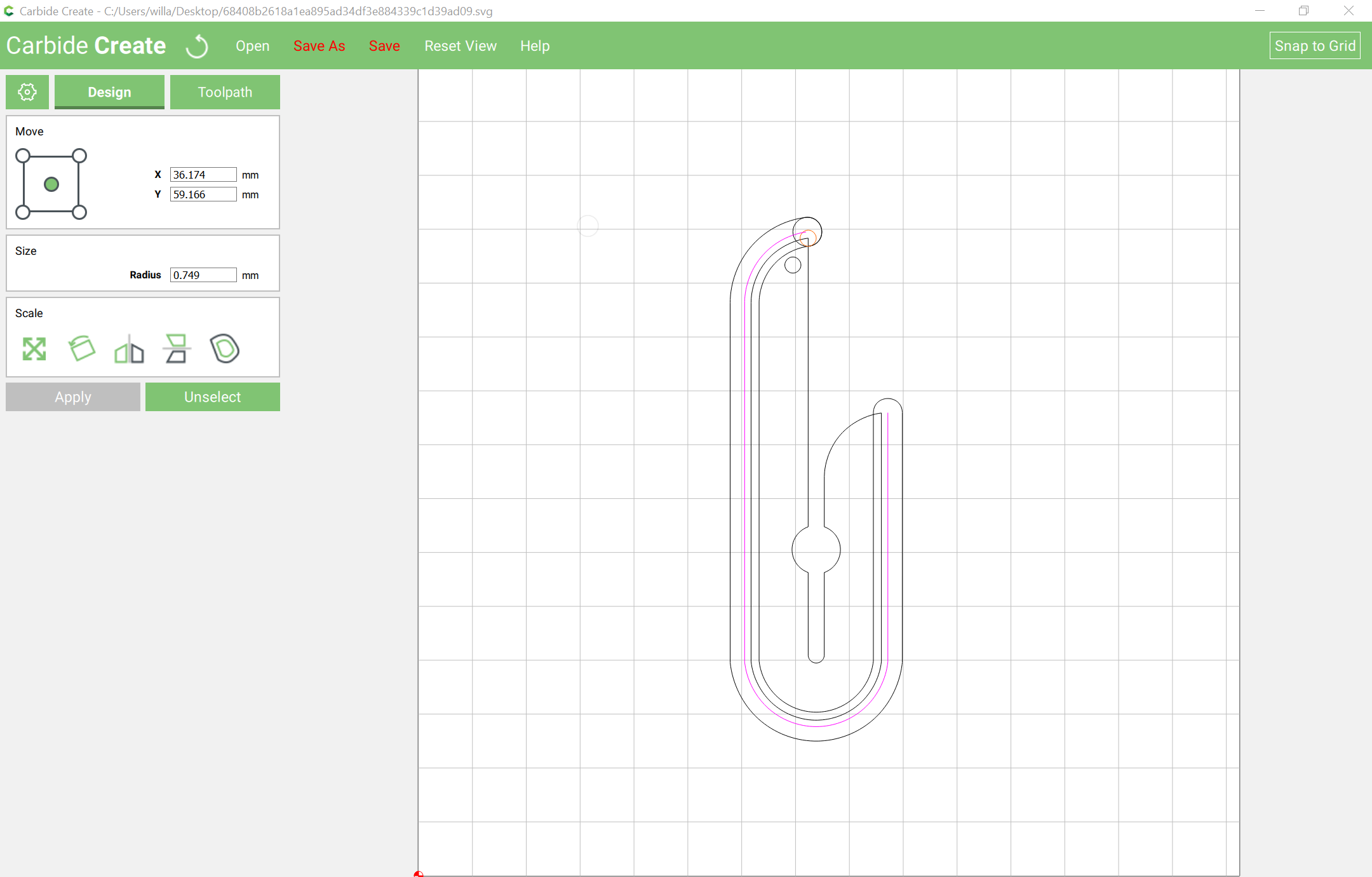
I guessed a thickness of 5.5mm to arrive at:
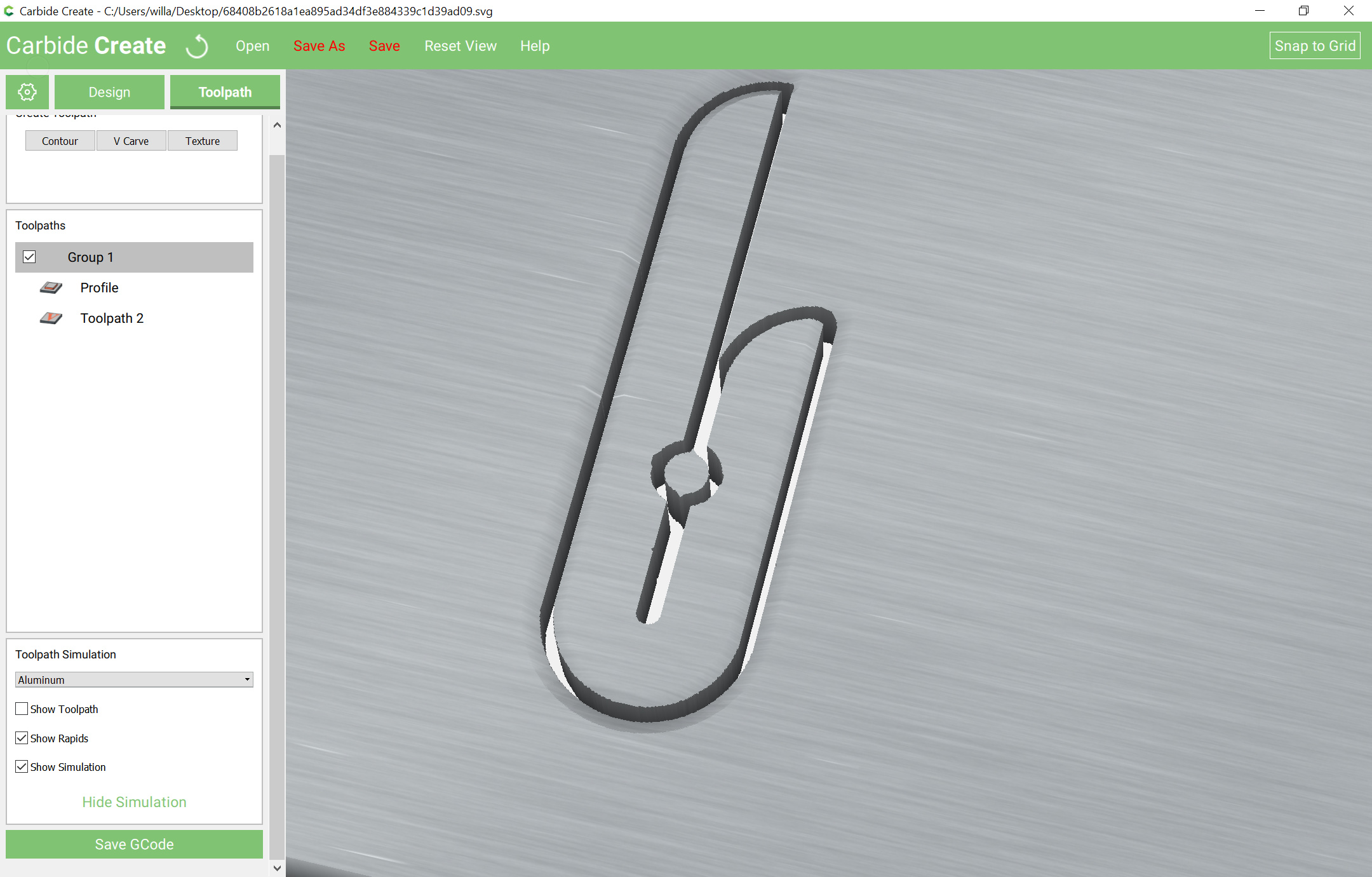
Attached.

chamfer_example.c2d (197.9 KB)
68408b2618a1ea895ad34df3e884339c1d39ad09

Will thank you for breaking this down for me. It really helps a great deal.

Could you please explain what you mean by: “We select the lines which make up the chamfer and expand that stroke by that dimension with a rounded cap”.

Also, what kind of end mill would you suggest for this?

Some vector drawing tools will have a tool which allows one to select an open path and expand it to become a closed one which represents the stroke.

In Inkscape one would do this by selecting the path, assigning a stroke style of the desired width with a rounded cap:

then in Inkscape do Path | Stroke to Path to arrive at:

I used a #301 and a #122 in the Carbide Create file — I think the #122 might not have sufficient flute length — please check that before committing to anything.

Thanks very much Will. I shall go ahead and download Inkscape and try this out.

I’ve never used a chamfer bit, so I can’t give an objective opinion on it. I have only ever used straight flute vbits, 1/4" and 1/2"

Will, although I changed a few dimensions, I followed your instructions and used Inkscape to create the chamfer tool path. When I import the saved svg file into CC, there is always one path that remains open. Can’t figure out why? I checked it in Inkscape and it appears closed but in CC it appears as a few pink lines.

Could you please let me know what I’m missing? Thanks :slight_smile:

Hook%20test
Hook test.c2d (167.1 KB)

You can see that the paths in Inkscape are not closed by selecting the shape and filing it. (again, Inkscape allows it to be filled, which is wrong).

You need to identify where the path nodes are not connected and join them.

If you have difficulty someone more experienced with Inkscape should be able to assist, or perhaps you could do it in Illustrator — it does have tools for this sort of thing after a fashion.

If you’re inclined, it ought to be simple in Serif’s Affinity Designer which is modeled on Freehand, in which application this is a simple checkbox.

Apologies for the back and forth. I finally figured out how to close paths in Inkscape and now it works perfectly.

As for the chamfer operation, I chose a Vbit from the menu in CC, selected the orange chamfer toolpath but now I get this:

Could you please explain this?

Thank you for your patience :slight_smile:

Hook test 3.c2d (164.2 KB)

Congratulations!

The odd little extra movements are caused by Carbide Create converting everything into polylines and said lines not always matching up. Vectric Vcarve can emit G2/G3 arcs, and keeps things internally as curves, so does a better job if you’re interested in a commercial option.

If you’re running Fusion 360 I suggest you watch John Saunders of NYCCNC YouTube video on chamfering.

I know you’re way past it by now but to answer your question about F360, yes, it’s very easy to toggle between closed and open paths. Hold down your alt key while in selection mode.

Thanks Heathenx, good to know.

Thanks for the tip Raymond. I’m still trying to decide whether I should fully invest my time in Fusion 360

So can I go ahead and chamfer with CC and that file? Not sure I want to invest in another software at this point.

On the topic of chamfers, I’m trying to cut out this pentagon with a chamfer. Based on what I’ve learnt so far, I created a slightly larger pentagon to act as the tool path for the Vbit.

What I got was these weird blue tool path lines which criss cross across the object. Also, using CC’s V Carve option, there is no option to control the depth of cut.

Help please! Thanks in advance.