Debugging is always fun. Let us know how it goes. The machine is definitely up to the task. ![]()
1 Like
The machine looks great and so do the chips.
I for sure recommend adding a MQL. A Maglube single port made a big difference on my friends Tormach 24r with cut quality and made the tool stay cool to the touch but it was costly up front.
If I didn’t already have a Unist on the way I would highly consider trying the Noga MC3000 dual tip.
It has a very fine fluid adjustment and I would be highly curious if it can be run with a high end hydroponics pump as a low wattage solution vs running a traditional air compressor. I have a 100w 3566 gph air pump that puts out a great air blast when ran through 1/2" lock line with a 1/4" tip.
I find the key for using the 100w air pump is to use the larger feed line and only taper down at the very tip to get the highest air flow. I want to drill out the feed port of the pump to a larger size and epoxy on a larger fitting to see how much flow I can gain. It uses the same front pump housing as the smaller 50w just with a larger motor and longer rotor so there should to be room for improvement if I go from a 1/4" ID port to 1/2" or possibly larger.
It should be noted that the air flow from those style pumps is rapid pulsing not a steady stream.
2 Likes
This topic was automatically closed 7 days after the last reply. New replies are no longer allowed.
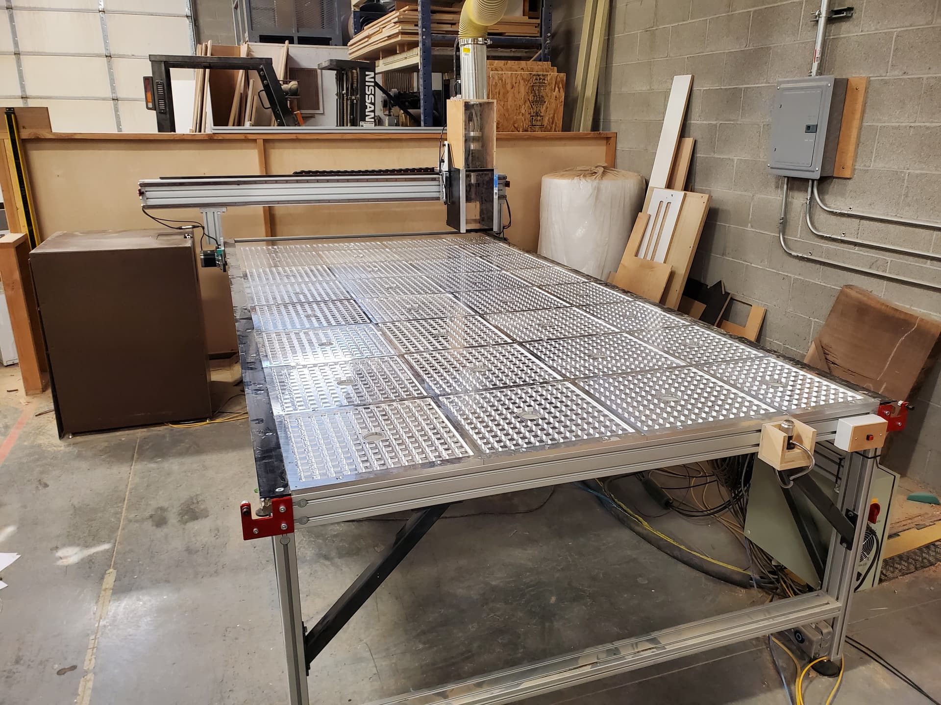
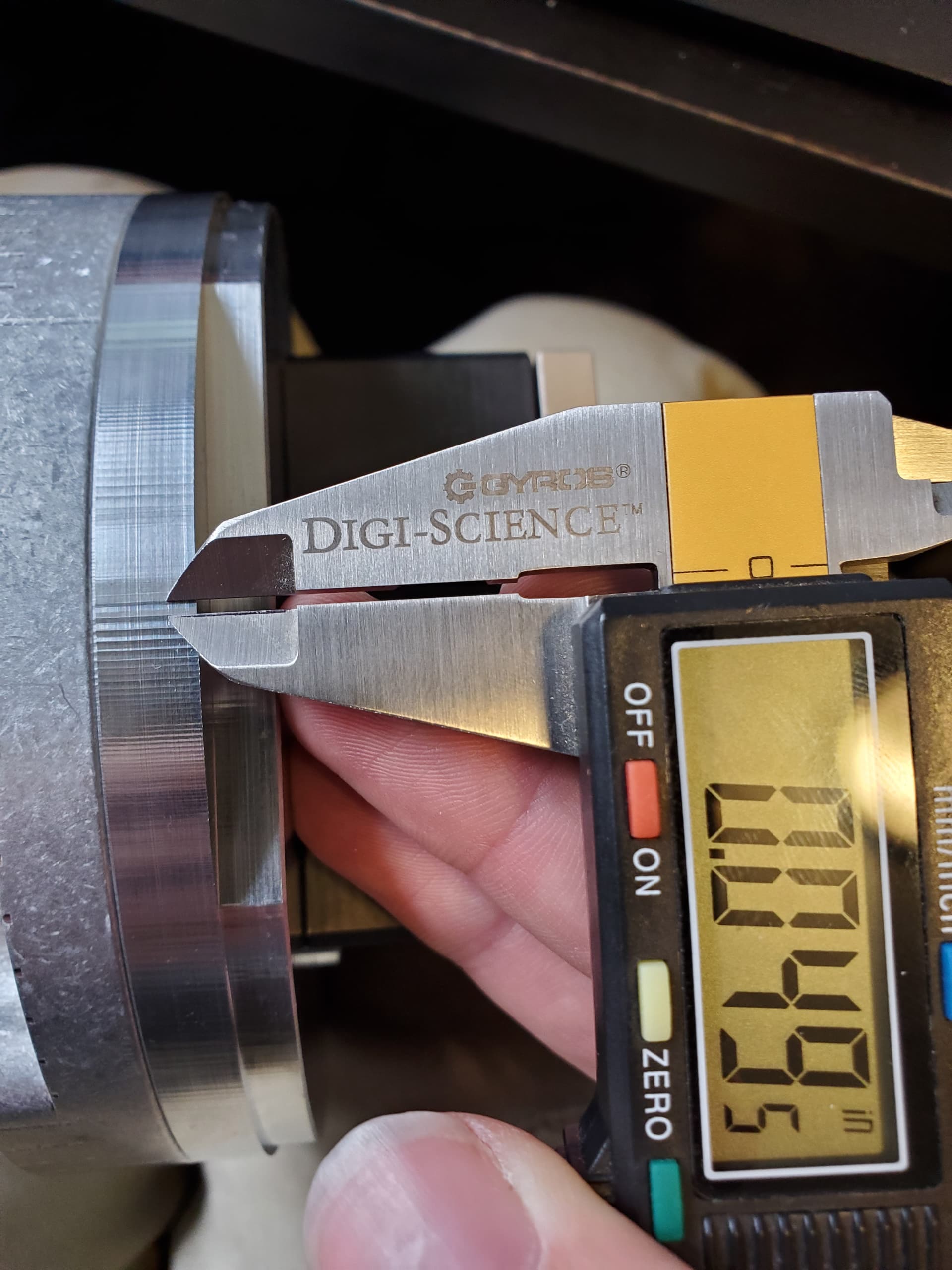
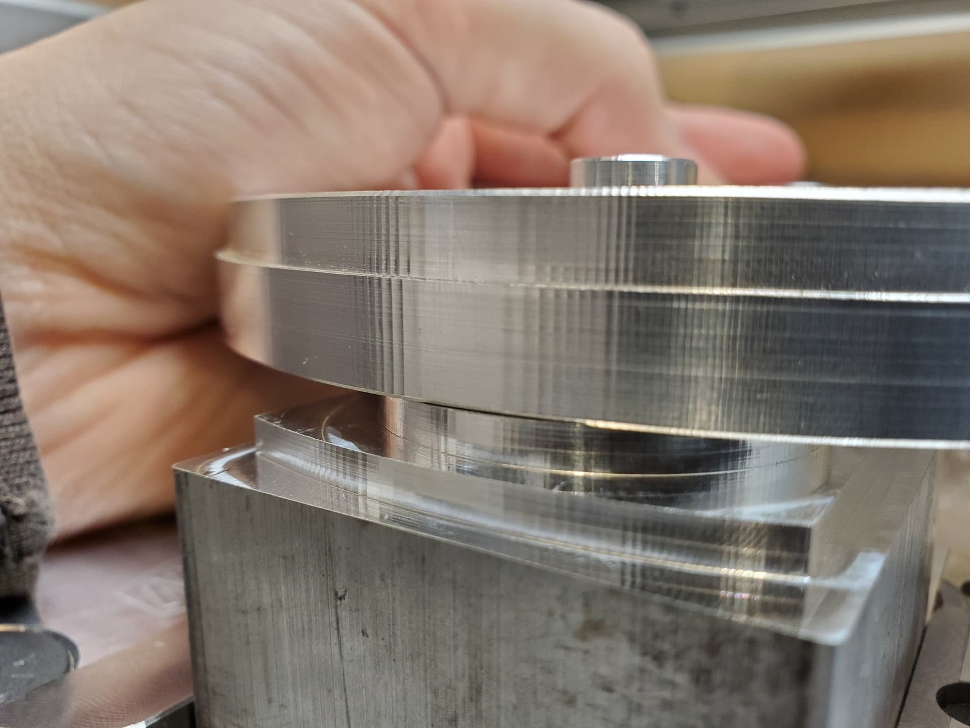
So I am finally getting back to this adventure and have a few things to share. First, the plate job went great. The only problem I had was caused by the cheap shaft couplings I used. One came loose in the middle of a run. Luckily, I did not have to scrap the part. Here is a picture of the final product:
I have started to chase down the small things now. I calibrated belt tension and steps per mm. With that done, I was able to hit tolerances of +/- 0.0005" in delrin without too much effort other than a finishing and spring pass.
I am pretty happy with that but I do have an issue with keeping the machine square. Even with the machine frame being square to my fixture plate and me pulling the gantry against the stops when I power it up, it doesn’t stay square. I have found that the steppers don’t consistently rotate to the same full step position when I turn the power on. I haven’t tried using shims between the frame and the gantry on power up but since the amount it is off square varies, I doubt it would really help.
I know I said in the beginning that I would not be changing out the controller… I have changed my mind. After a couple weeks of trying to solve my squaring issues I have come to the conclusion that I need the machine to square itself during homing. That means I need to have another sensor on the Y axis. I think there are ways to do this with GRBL but if I am going to replace the controller, I would rather just go with another type. I will be switching to Mach4 and an ESS. I picked this because I am already familiar with both and have experience customizing them. I am also motivated to switch controllers in order to have a machine at home that I can prototype Mach4 customizations without interrupting my work machine.
I plan on keeping all the existing connectors and homing sensors so I can go back to the CM board if I ever want to.
I have the ESS, power supplies, cables, connectors and breakout boards already and have started on wiring everything. I have one more 5v proximity sensor coming for the second Y limit sensor. I will post pictures when I am done wiring the electronics.
Does anyone know off the top of their head what the microstepping is set to in the stepper drivers on the CM board? I’m sure I can figure it out if no one does. EDIT: It looks like the answer is 8x microstepping.
6 Likes
I wish I could answer your micro stepping question but it’s above my knowledge but I am looking into Atc options for my HDM and was wondering how do you like the S30 from Cnc Depot? How much air does it use when running and how well is it performing for you?
I heard they use a fair amount of air for the dust sealing but I hope it’s not much and would like to hear about your experience with it so far.
Overall, I like our S30. The manufacturer has been easy to work with and it is a decent price for what you get. Some things to note/thoughts:
- Clean and dry air is very important. You need a good 2 stage 0.3 micron or better filter/dryer at minimum.
- The drawbar should be run at the max PSI of 120 for reliability reasons.
- It is very important to keep the spindle taper and all your tool holder tapers clean. I would not recommend a wine rack style tool changer unless it has a cover and an automatic tool taper blow off when it changes a tool.
- I wish it was liquid cooled. When running for long periods the spindle and spindle taper will get warm (not unreasonably, just warm-hot to the touch). Thermal growth causes the tool holder to get slightly stuck in the taper. Not enough to cause issues as long as you always feed the drawbar with 120 PSI. This problem shows itself most when you pick up a cold tool with a warm spindle. I am considering making a small cooling jacket for the spindle nose.
- The air seal takes enough air that I probably wouldn’t run it on a consumer grade compressor. My guess is that it takes somewhere between 1-3 CFM at 100 PSI constantly. It would probably work fine but I would be concerned with how often the compressor would cycle. The more often it cycles, the more likely you are to have moisture in your air. Something with a large tank would probably be fine.
- I wish I had gotten the S30C. You don’t gain any more power or torque with the 24,000 RPM version vs the 18,000 but it would be nice to have the extra RPM when we run small tools.
It is pretty heavy so I am not sure if it would work great on an HDM but it is a good spindle overall. It is a good match for our machine power wise. We typically use 1/2" tooling and run most things at 1/2" depth of cut full slotting in plywood with no issues.
2 Likes
Thank you for the in depth feedback on the spindle. I am looking at the Fm 30c as it is lighter and I couldn’t imagine being maxed out at 18k as I run a lot of single flute cutters in aluminum so 24k is a minimum requirement of any spindle purchase.
I have a 32 gallon 2 piston 2hp compressor but it cycles every couple minutes just running my MQL so it would be almost constant feeding an extra 1-3 cfm spindle. I need to look into changing my MQL system out if I intend to run a spindle with that high of air consumption with my compressor setup or look into adding an extra tank.
I look forward to seeing how your build progresses.
2 Likes
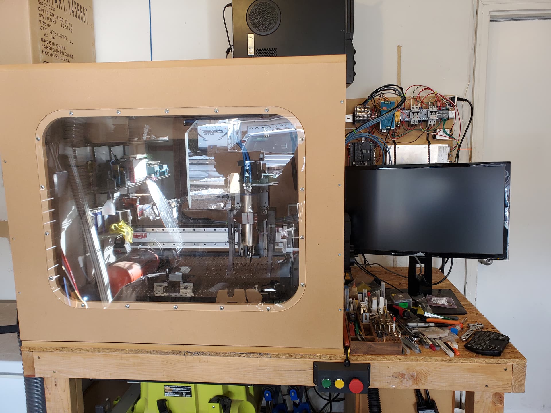
So after many days of designing, testing, learning and upgrades I have a few things to report.
Before all that, some glory shots of the completed controller swap:
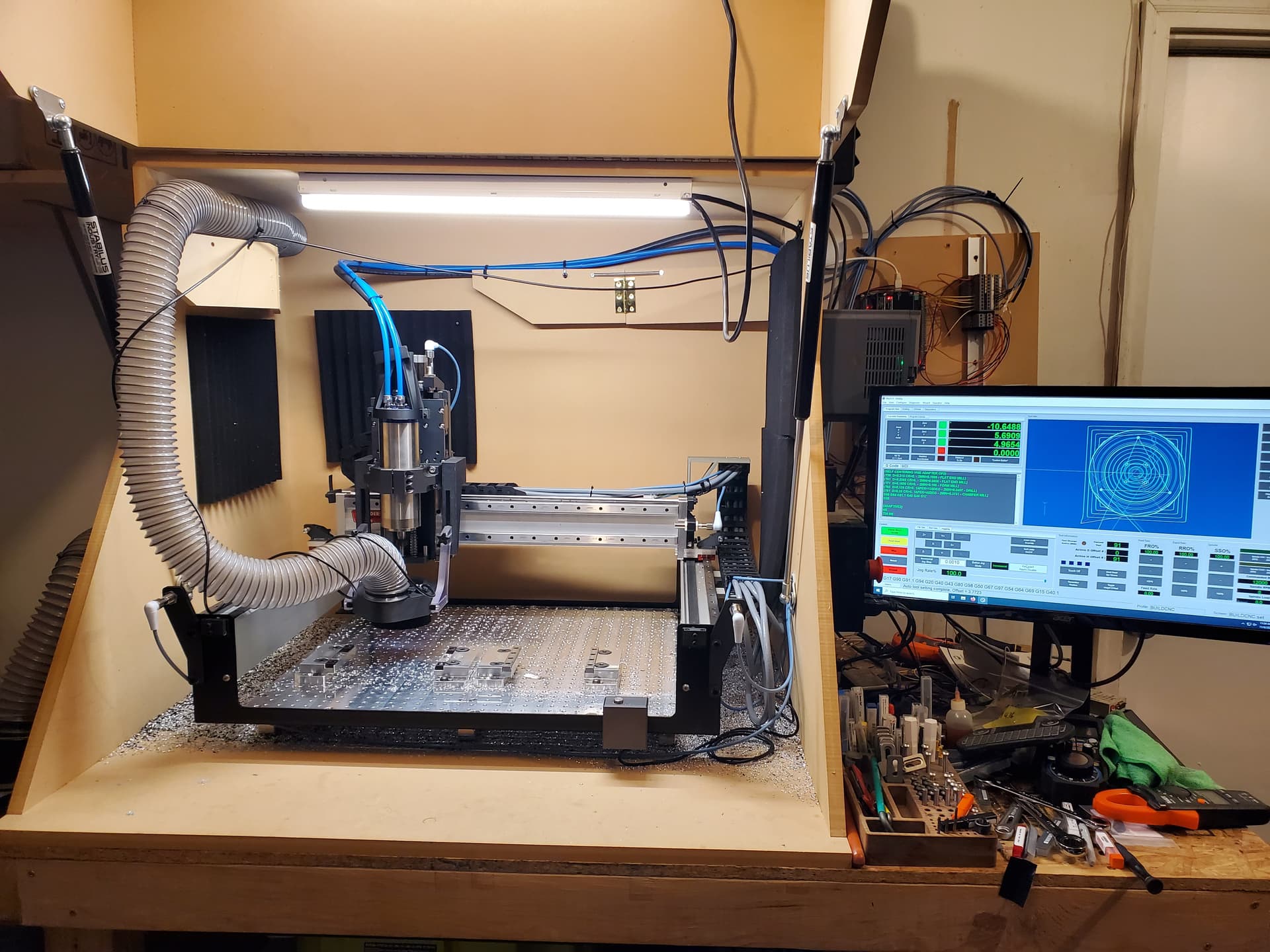
First, switching the controller out in order to get dual Y homing did significantly improve squaring. It was not quite as simple as just plugging in a new board. Since I am pretty familiar with Mach4 with an ESS, I chose to use those as my new controller.
https://www.machsupport.com/software/mach4
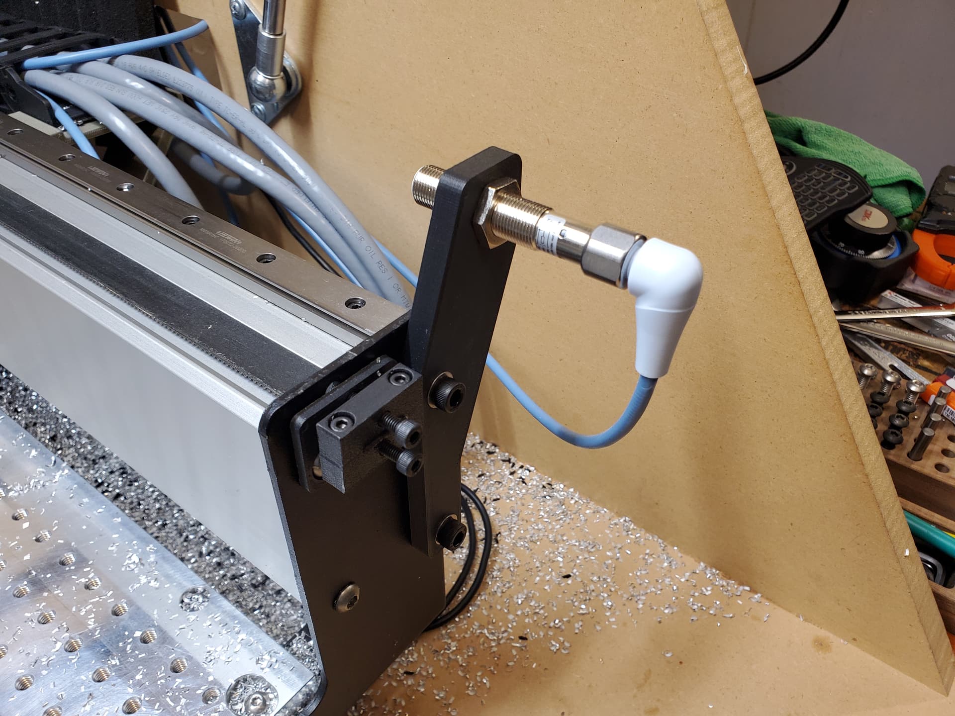
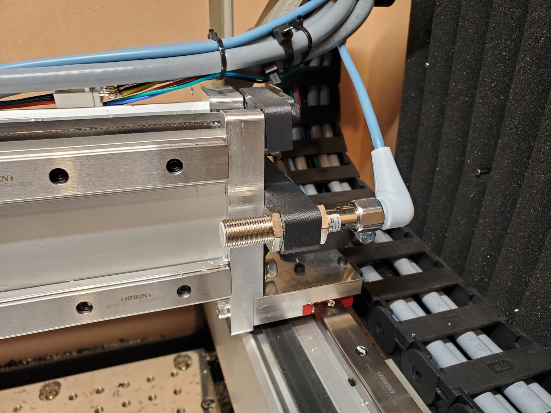
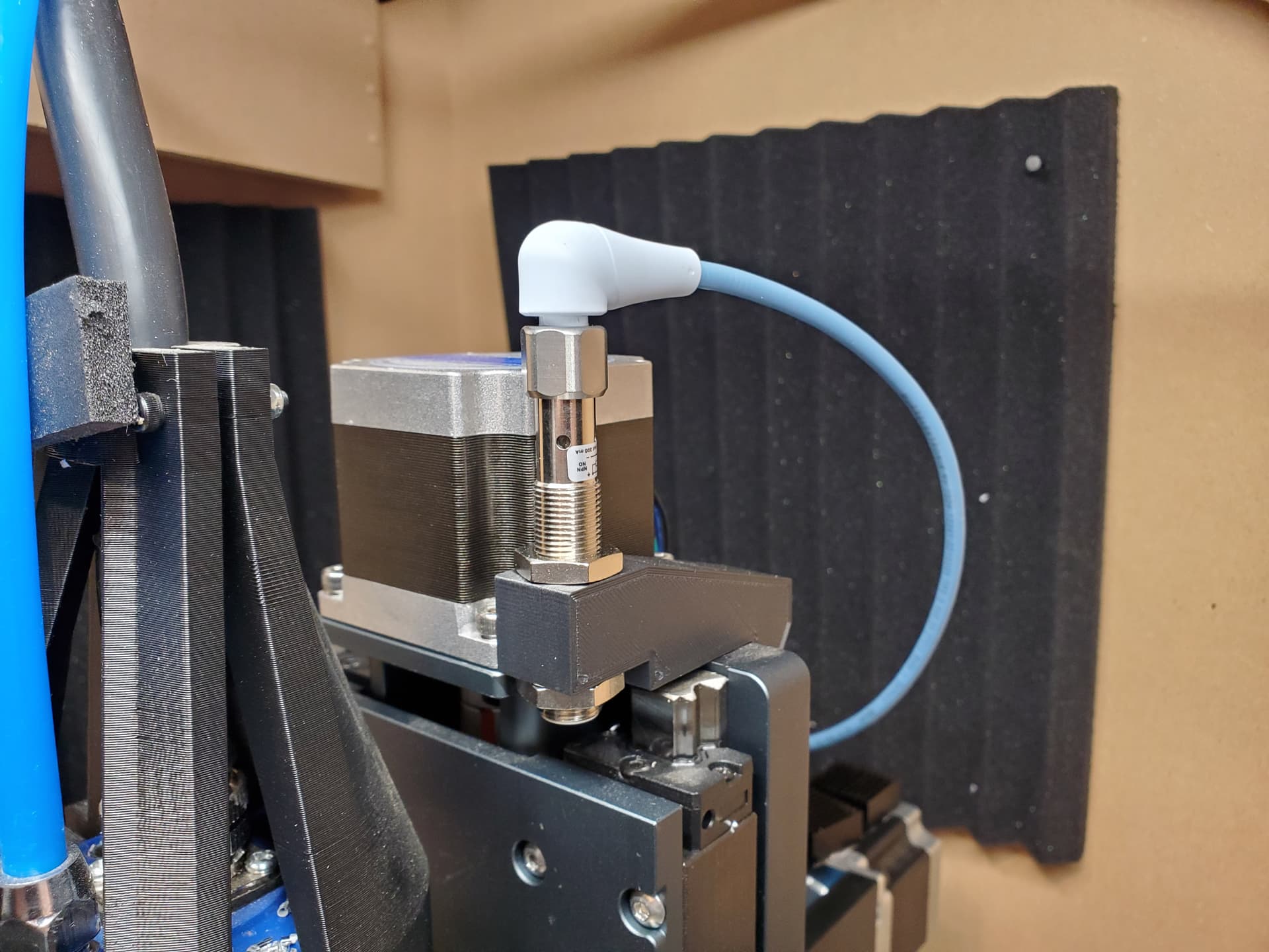
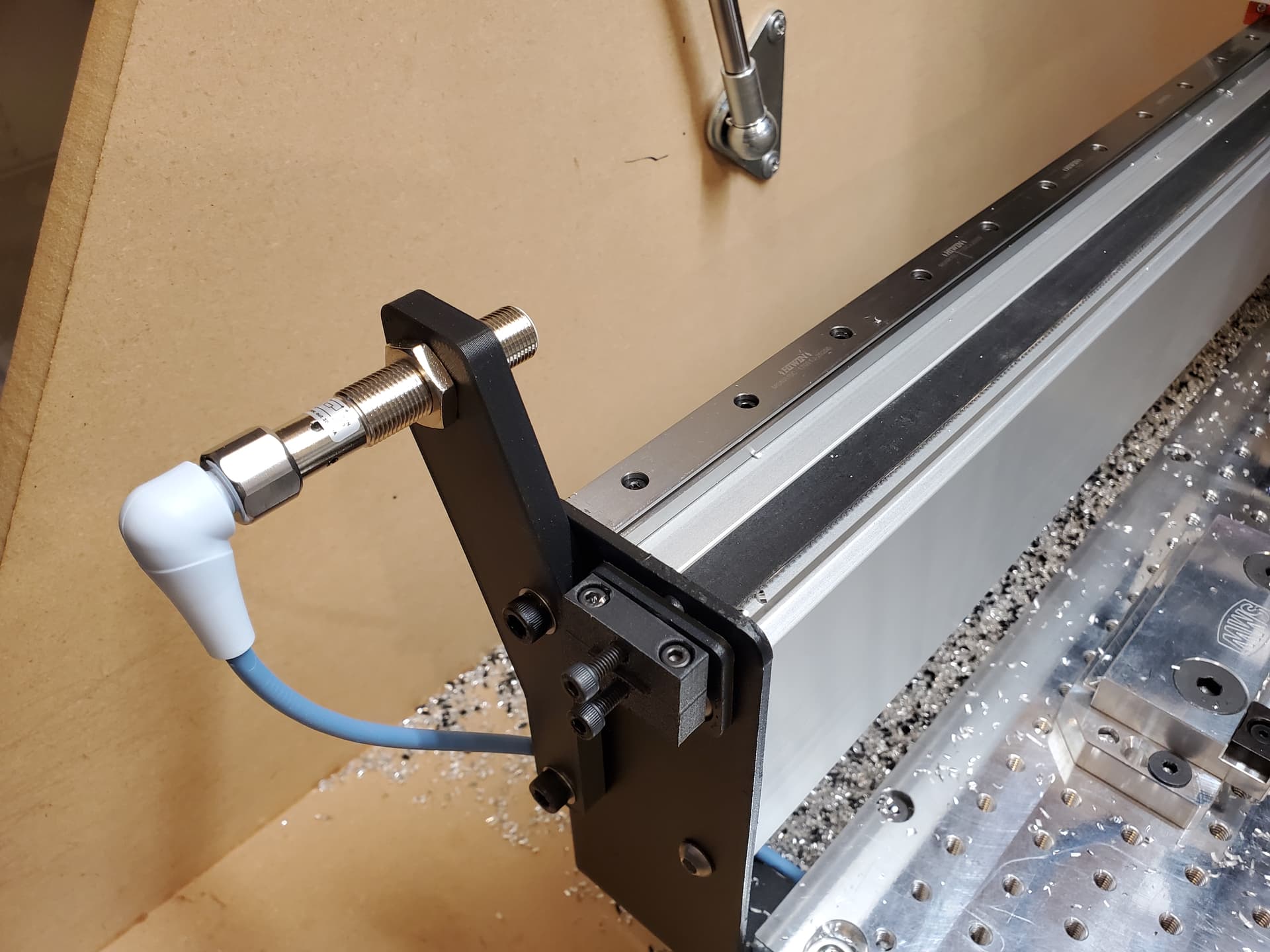
I use a custom screenset that is loosely based on one of the default options. For the breakout board, I first tried a C85 and a C10D from CNC4PC. The C85 has built in stepper drivers that could handle the 2.8A rating of my 0.9 degree steppers that I switched to (more on these later). Between both, there were plenty of inputs for the existing homing sensors, bitsetter, bitzero and my feed hold switch. I purchased an additional 5v inductive sensor for the other Y motor and was able to get dual Y homing to work. I ran this setup for about 2 months but continued to have issues with squaring. I had a few instances where it would home and then loose steps trying to square the gantry. With a little bit of investigation I determined that there were 2 things contributing to this. First, I was getting a little bit of interference on all my 5v homing sensors. If I moved the machine very close to home, you would see the sensors toggling back and forth. I found that if I reduced the amperage to the steppers, it would improve but not disappear. Second, as it started to get cold in my garage I noticed that the 2 Y axis sensors would change their sensing distance different amounts based on the temperature. Based on those observations I purchased a whole set of 24v short distance inductive sensors. 24v sensors are significantly less susceptible to EMI and the short distance gives me better repeatability because the +/- sensing range on inductive sensors is defined as a percentage of the sensing difference. These are the sensors I got:
They have a sensing distance of 2mm and a repeat accuracy of <= 2% which equates to about 0.0015". With those I was able to significantly improve the reliability of homing in general and the dual Y homing worked great.
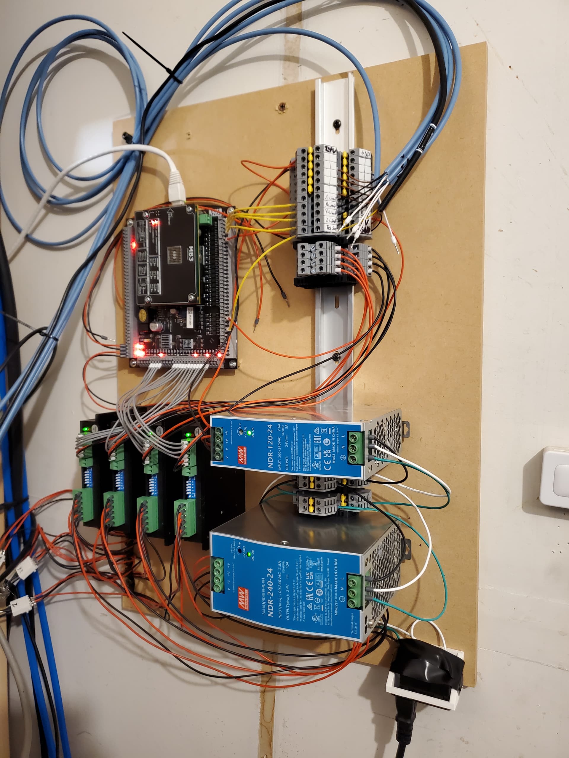
Another issue I had intermittently was that the machine would have trouble moving in 0.001" increments when jogging. I would click the button a few times and it would eventually snap forward a few thou. In a moment of irritation while trying to make a part with relatively tight tolerances, I decided I was done with the stepper drivers on the C85. They made a bunch of noise with the steppers and I assumed without thinking much about it that they were the cause of my issue. I swapped out the C85 and C10D with an MB3 from CNCRoom and 4 DM542T drivers from Stepperonline:
I have been mostly impressed with the MB3. It breaks out all 3 ports of the ESS, is relatively compact, accepts 24v inputs by default with everything being opto-isolated and requires only a 24v power supply. There are a few features that I haven’t had a chance to mess with yet. The analog 0-10v output for spindle control isn’t working for me. My VFD seems to want to go up and down in a 1500RPM range around the intended RPM. It did not do this with the C85 0-10v output. I did have a problem when I was re-wiring the VFD to the MB3. I accidentaly bridged 2 of the IO ports on the VFD and caused some sparks. The VFD restarted and seems to be fine. Manual control with the pot on the face works as it should. I am unsure if the RPM fluctuation is a result of damage or if the 0-10v output from the MB3 is giving me troubles. I think I need an oscilloscope to find out. Sounds like an excuse to buy a new tool.
The new stepper drivers are much improved over whatever is on the C85. They don’t make any noise, the motion is much smoother and generally do what they are supposed to. I do think the enable circuit is kinda dumb on these. Rather than be enabled when receiving power, they are enabled with no power and disabled when you apply power. Seems backwards.
After all these upgrades, I have been able to hit +/-0.002" of the intended dimension and +/-0.001" of square without much trouble. I am very happy with the results. I think I could do a little better if I tune the backlash compensation available on the ESS.
Before I move on to the things I still want to do, I want to come back to the faceting issue I had on my original test part after upgrading to rails and new steppers:
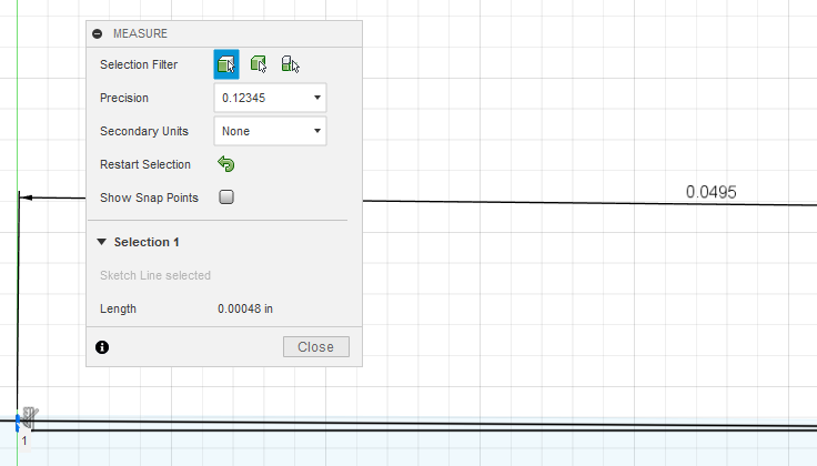
The problem you see in my earlier post is caused by running the steppers below their rated amperage. They loose a significant amount of torque and causes the faceting you see in that picture. With the new drivers, the only faceting you see is a function of the resolution available. Currently at 8x microstepping on 0.9 degree steppers, my resolution is just under 0.0005". In this picture you can see the result at the transition point of this interpolated circle:
Doing the math (cheating and letting F360 do it for me) tells me that this is functioning as it should:
I may experiment with the microstepping of the drivers and see if I can improve this further without loosing torque. I have more torque available with these steppers than the stock ones so I think I might be able to go up to 16x without sacrificing anything. I hope.
As for things I still need/would like to do:
- Solve probing conductive things. Because my spindle is grounded and I am now using rails, the bitzero no longer works when probing conductive things unless there is something non-conductive between them and my fixture plate. Does anyone know an easy way to solve this? Anyone that has done this rail upgrade already solved this? I suppose I could make some sort of tool that is only conductive at the tip to stick in my spindle when I am probing.
- Add a better E-Stop. Now that I have the ability to have an E-Stop that can cut power to the stepper drivers and VFD without cutting power to the controller, I would like to set that up.
- Reconnect my feed hold button and maybe add a cycle start button.
- Add some sort of chip deflection around the belts and rails so I can switch from using dust extraction to air blast for chip removal without getting chips in places they shouldn’t be.
- Add air blast with some sort of fogbuster equivalent. I would really like to do this but I am not sure if it will actually happen. The cost of a quiet compressor that can actually supply enough air without cycling constantly is pretty high. I may have to settle for lower pressure with a decent air pump.
6 Likes
so why would you not just use a regular 3D touch Probe? especially now that you’ve got Mach4.
I’ve been using this one on my mach4 shapeoko and it seems perfectly adequate.
3D touch probe
you can find them cheaper on Alliexpress but you wait forever for them.
1 Like
How do you manage the Z offset? Do you just measure off of a known point on your base? I have a wireless probe on my machine at work but that machine has an ATC so I don’t ever need to change the length offset.
I do use a tool table with tool offsets. I measure everything off of a 1 2 3 block and enter the offsets in the tool table.
when I install the tool in the spindle. I make a spacer that “bottoms” the tool in the spindle. That spacer stays with that tool, so each time I put it back in, I use the same spacer so the Z offset of the tool is pretty constant for that tool.
or you can use one of the dozens of auto tool zero macros available for Mach along with a tool setter touch probe.
By the way, I like your rails conversion, and hope to do the same on mine eventually. I will also be going with ball screws too.
1 Like
The belts on my machine are the limiting factor at this point. I am okay with this for now. The cost and effort to properly do ball screws is more than I am willing to do right now considering what I am able to achieve with the machine after the upgrades. If I were to go for ball screws, I would seriously consider putting my old carbide 3d controller and steppers back on and selling the machine. Then I would buy a 2’x2’ 5 Pro and swap in my steppers and controller.
2 Likes
Yes, a 5 Pro or HDM may be $$$ wiser move for myself as well. But I do like to tinker, so conversion it is, for me ![]() Besides, retired old engineering/manufacturing guy with nothing but time.
Besides, retired old engineering/manufacturing guy with nothing but time.
2 Likes
Totally get it. The desire to tinker and learn is a huge part of why I do the projects I do.
1 Like
Wait…people buy these machines and DON’T tinker? gasp ![]()
I don’t think I’ve bought anything in 20 years and left it alone. ![]()
6 Likes
After some testing and a small upgrade I have some information on increasing microstepping. The stepper drivers I am using are able to have 24v to 48v input. Higher input voltage equals higher available torque. To make sure that I would maintain torque while increasing the microstepping, I upgraded from 24v to 48v. I then tested both 16x and 32x microstepping. 8x with my 400 steps per rev motors is about 2000 steps per inch. I first tested my most aggressive aluminum recipes to make sure I wouldn’t miss steps. Neither 16x or 32x had any issues so I moved on to testing arc resolution at 32x.
Not surprisingly, 32x microstepping produces much smoother arcs at the transition between X and Y. Here is a picture:
The top part was done with 8x and the bottom part is with 32x. It is difficult to tell in the image (some facets on the 32x part dont even show) but the flat spot is much smaller and each individual facet has a much smoother transition. I bet I could go up to 64x but I think that it would be well into the diminishing return realm for a belt driven machine with about 0.0005" of backlash. My available resolution at 32x is about 8100 steps per inch or 0.00012".
2 Likes
This topic was automatically closed after 23 days. New replies are no longer allowed.
After a bunch of work, I have another few upgrades and fix to share.
I solved the problem I was having with spindle speed control by switching to an external PWM to 0-10V generator. It isn’t super accurate (it can be off by as much as 300 RPM depending on where in the range I am running the spindle) but it doesn’t swing back and forth. Not sure why I was having a problem because the voltage reads correctly with a multi-meter from the MB3. Like I said earlier, I think I would need an oscilloscope to figure it out. At least my VFD isn’t broken.
Since I use a separate power supply for the stepper drivers, I decided to do a real hardware based E-Stop that cuts power to the drivers and the VFD but not the controller. Doing this adds quite a bit of hardware:
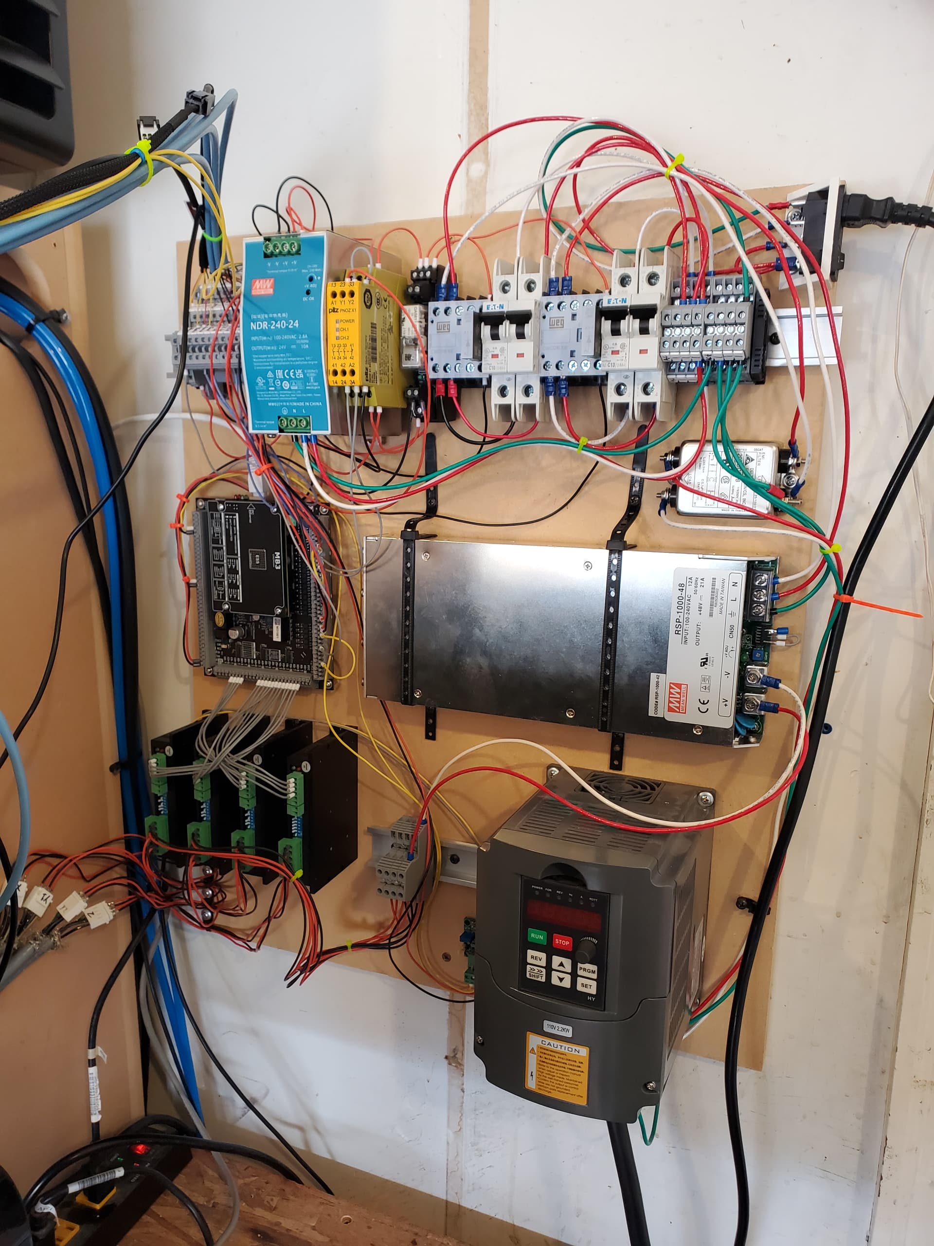
I added an E-Stop controller, a safety relay (more on this in a sec), 2 contactors, 2 breakers and all the VFD stuff that used to be separate. Here is a simplified diagram:
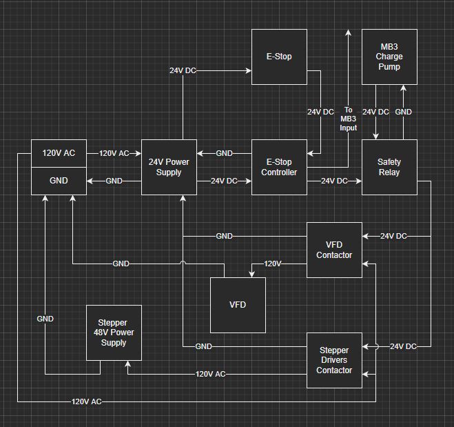
Now if I hit the e-stop, the contactors disconnect the power to the VFD and the stepper driver power supply. The e-stop controller also has an output that connects to the MB3 to inform Mach4 if the e-stop is active. For those that don’t know, an e-stop controller is essentially a relay with some status lights and a hardware self test function that runs every time it is turned on. The e-stop switch just cuts power to the controller which causes the circuit to the coils on the contactors to open.
Also in that diagram is that safety relay connected to the “charge pump” circuit on the MB3. Mach4 has a function that always produces a PWM signal when it is running properly. The MB3 has a circuit that receives this PWM signal and turns on an output. If Mach4 or the PC crashes that PWM signal will stop which will turn off the output. You can get all kinds of strange behavior if a piece of software does not close nicely and the last thing you want is for the ESS to continue commanding the steppers or spindle after the software controlling it has closed. Mach4 calls this functionality a “charge pump” circuit. That safety relay opens the contactor coil circuit if Mach4 isn’t running.
I put the e-stop, feed hold and cycle start buttons all in a 3D printed enclosure and attached that to the front of my table/bench:
Last but not least, based on the recommendation here:
I added a similar 3D touch probe. I built a macro that measures the probe length off of a known point on the machine when I switch to it. I have found it to be repeatable to less than I can measure reliably which is 0.0002". It is so nice to be able to probe things directly.
This is the final iteration I am going to do on a Mach4 based controller. I plan on switching to LinuxCNC when I get time. Mach4 has a few shortcomings that make it not a viable option for my work machine. Since this whole controller swap was largely motivated by the ability to test out things for work, it doesn’t make much sense to stay on Mach4 if I am switching the work machine to LinuxCNC.
Next on the list is either the LinuxCNC swap or chip shielding of some sort for the rails and belts followed by air blast. Has anyone done chip covers or deflectors for their Shapeoko Pro or HDM? I haven’t been able to find any examples to take inspiration from. I’m sure I can figure something out if someone hasn’t already done it.
4 Likes