Hi, I’ve purchased n stl of chess pieces I’d lik wto make but I’m having a nightmare getting CC Pro working with it. I’m not sure whare to start and how to use the dxf effectively with the STL in CC.
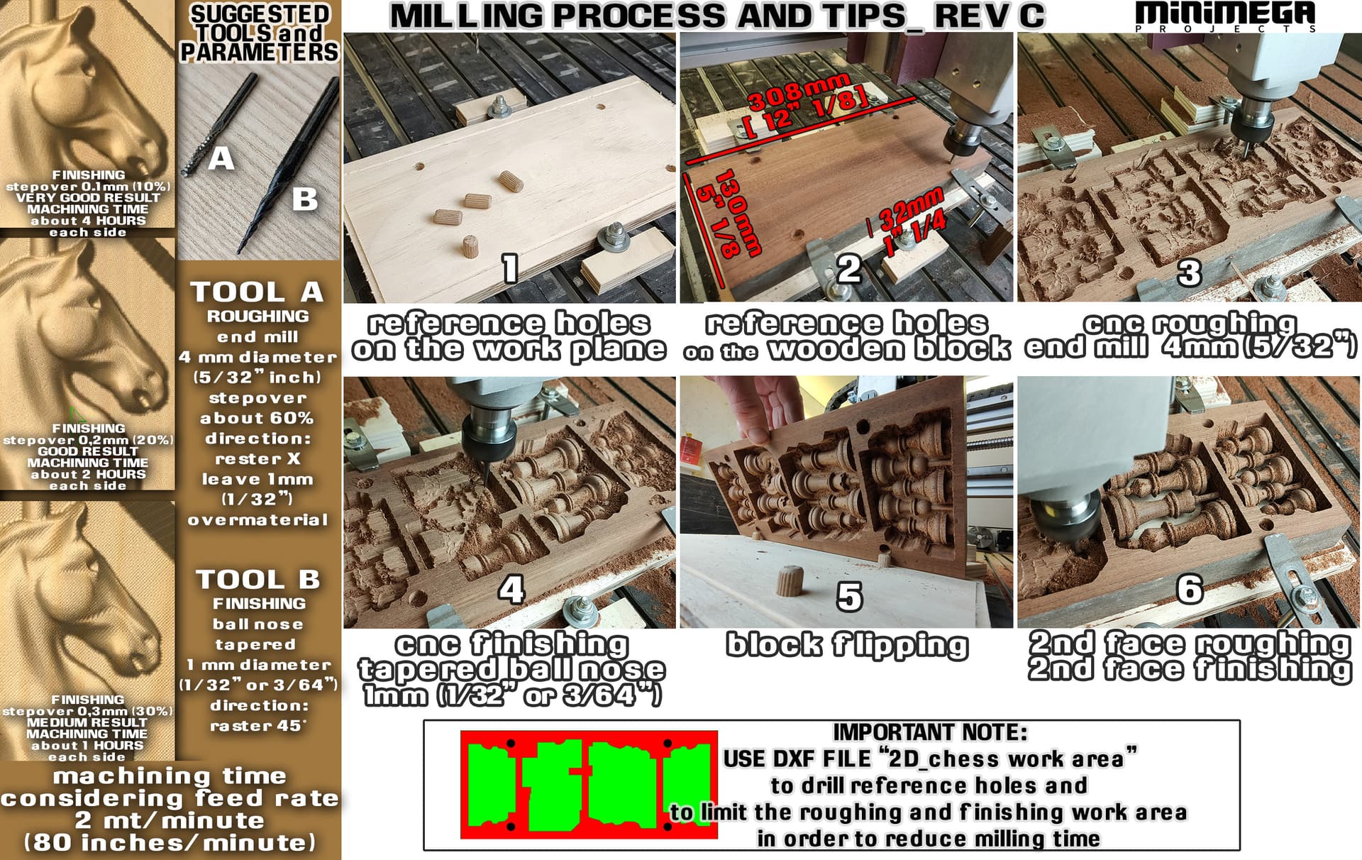
There’s a dxf file too that the creator says I should use to limit the roughing and finihing work area - I’ve attached the ‘documentation’ I think the file might be familiar to some. I’ve always had problems with CC 3d modelling mainly because I have no idea what I’m doing and what all the options are for.
That said, it should just work to prepare the stock in one file, then in a second drop in the STL, do the roughing and finishing pass for one side, then flip, then cut the other side, no DXF necessary.
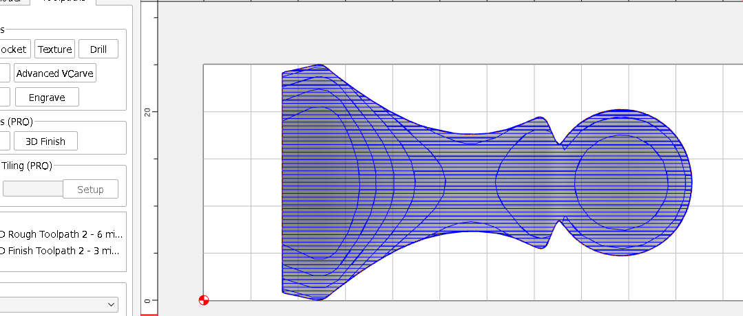
I think the dxf was supposed to limit the area that was worked on so that time wasn’t wasted - without it, CC thinks it’s going to take 595 minutes for the roughing pass. It’s 206 min for the finish pass. That’s just for one side, so after flipping it’s the same again. Seems like a very very long time.
You gotta think 4th dimensionally when doing double sided 3D carves - the smallest shifts basically get doubled by the flipping. Looks like you need to surface your stock material first to ensure it is at spec thickness before you carve the first side. Then the flip-side toolpath needs to have a stock thickness to match with the STL correctly located within. Unless your stock is perfectly symmetrical with the depth of the STL perfectly centered within it, just flipping it & using the same toolpath won’t work properly.
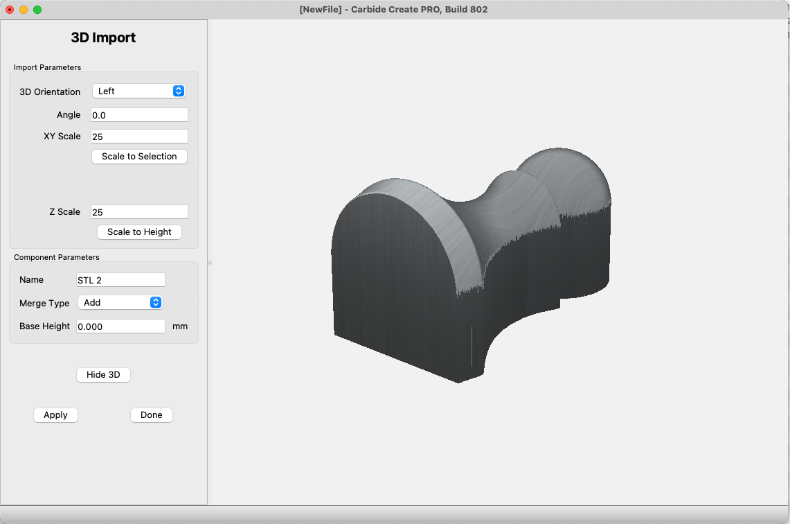
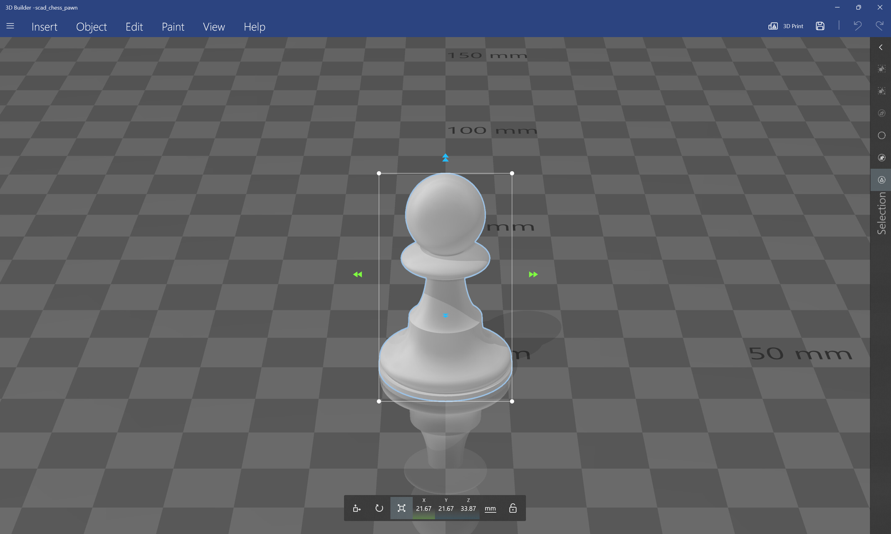
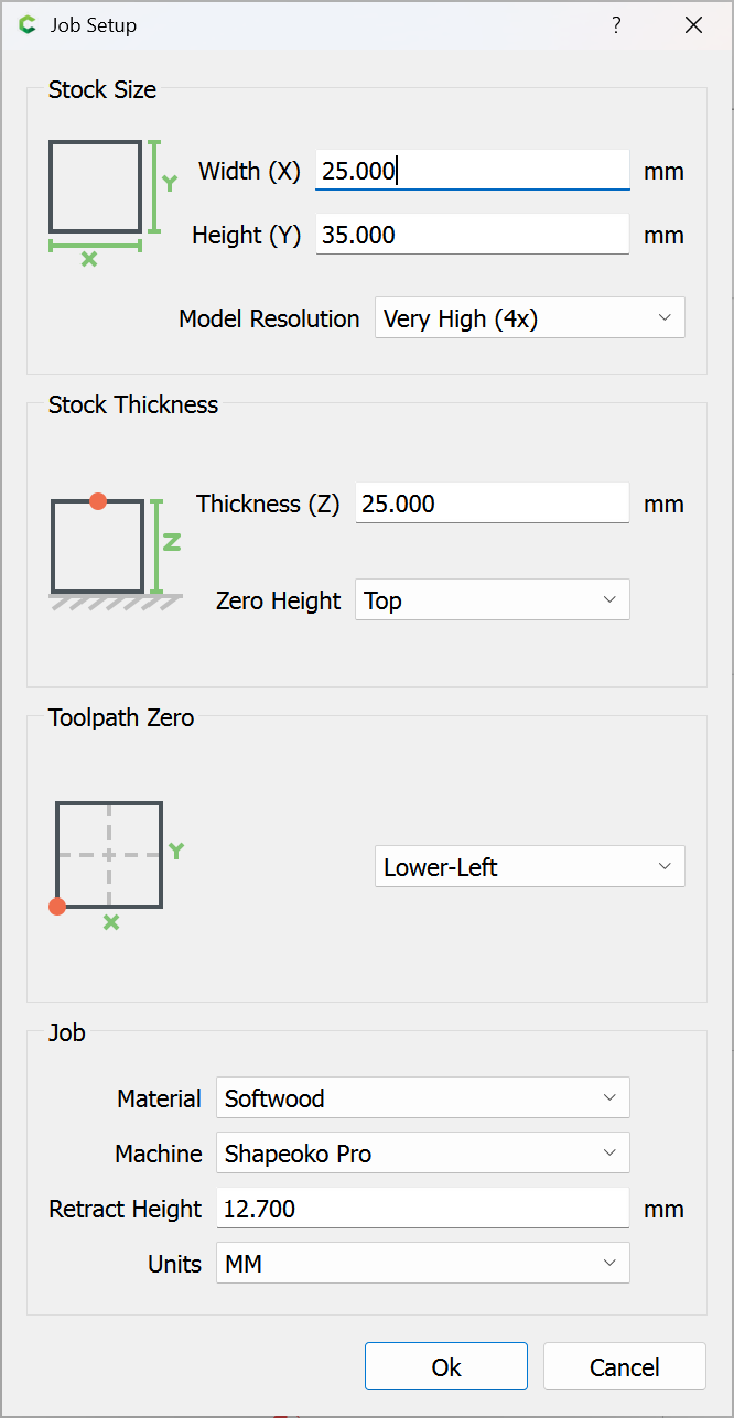
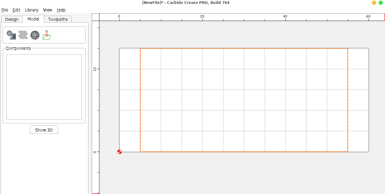
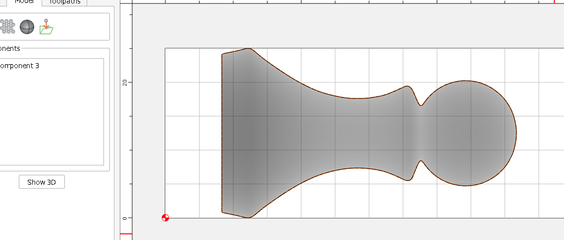
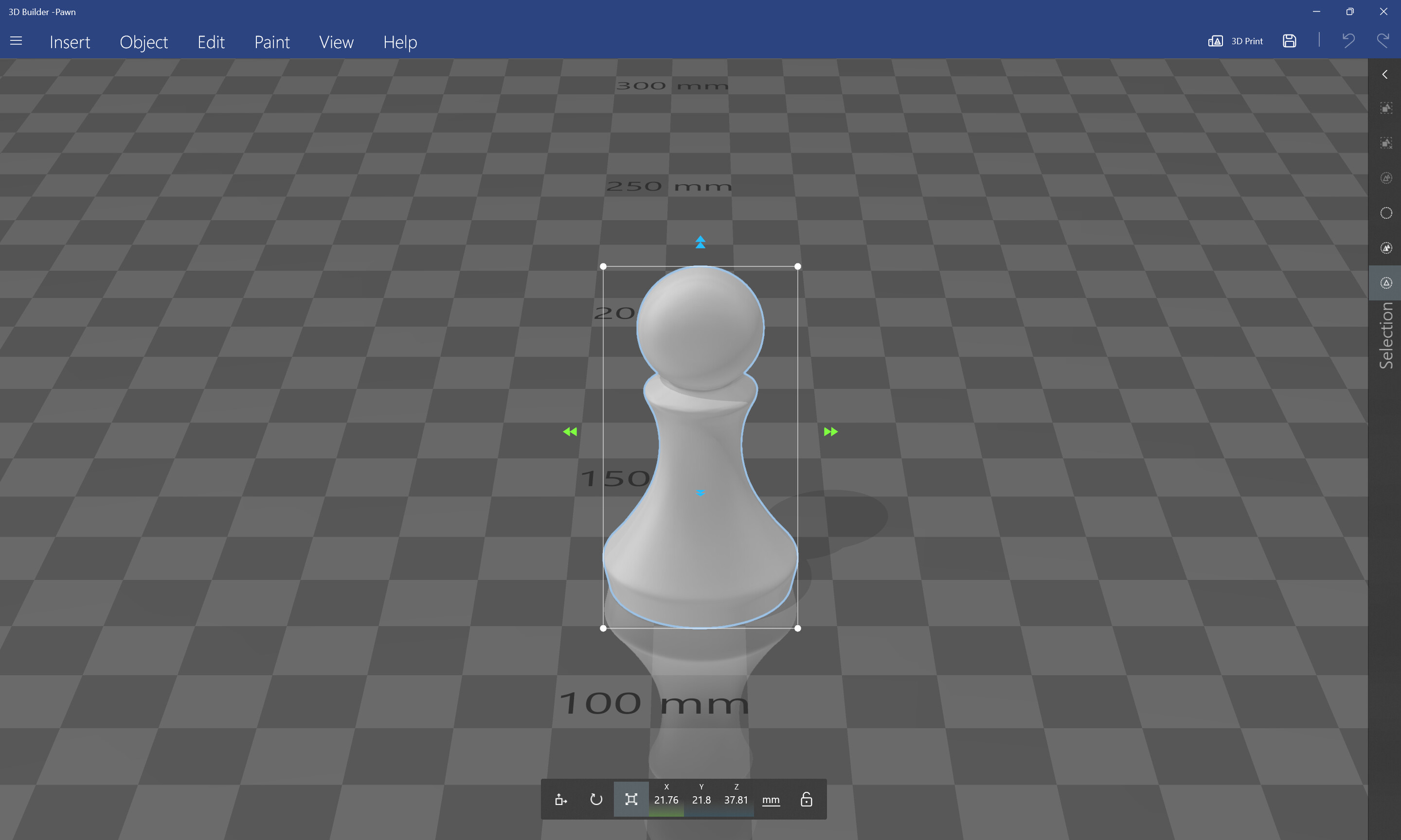
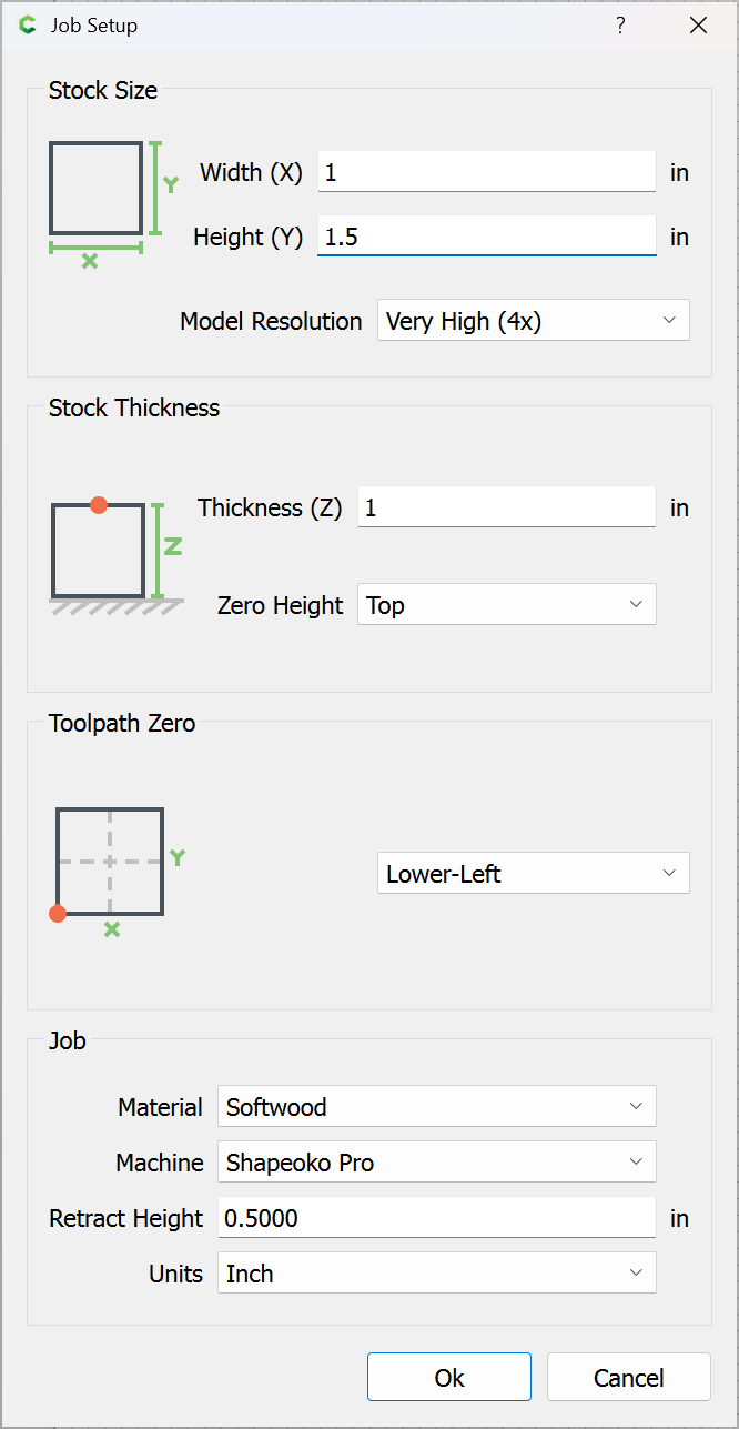
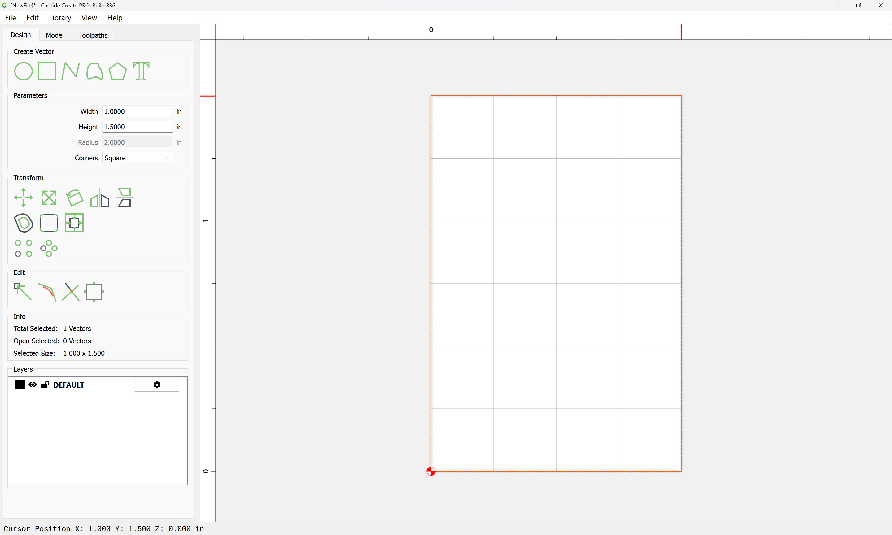
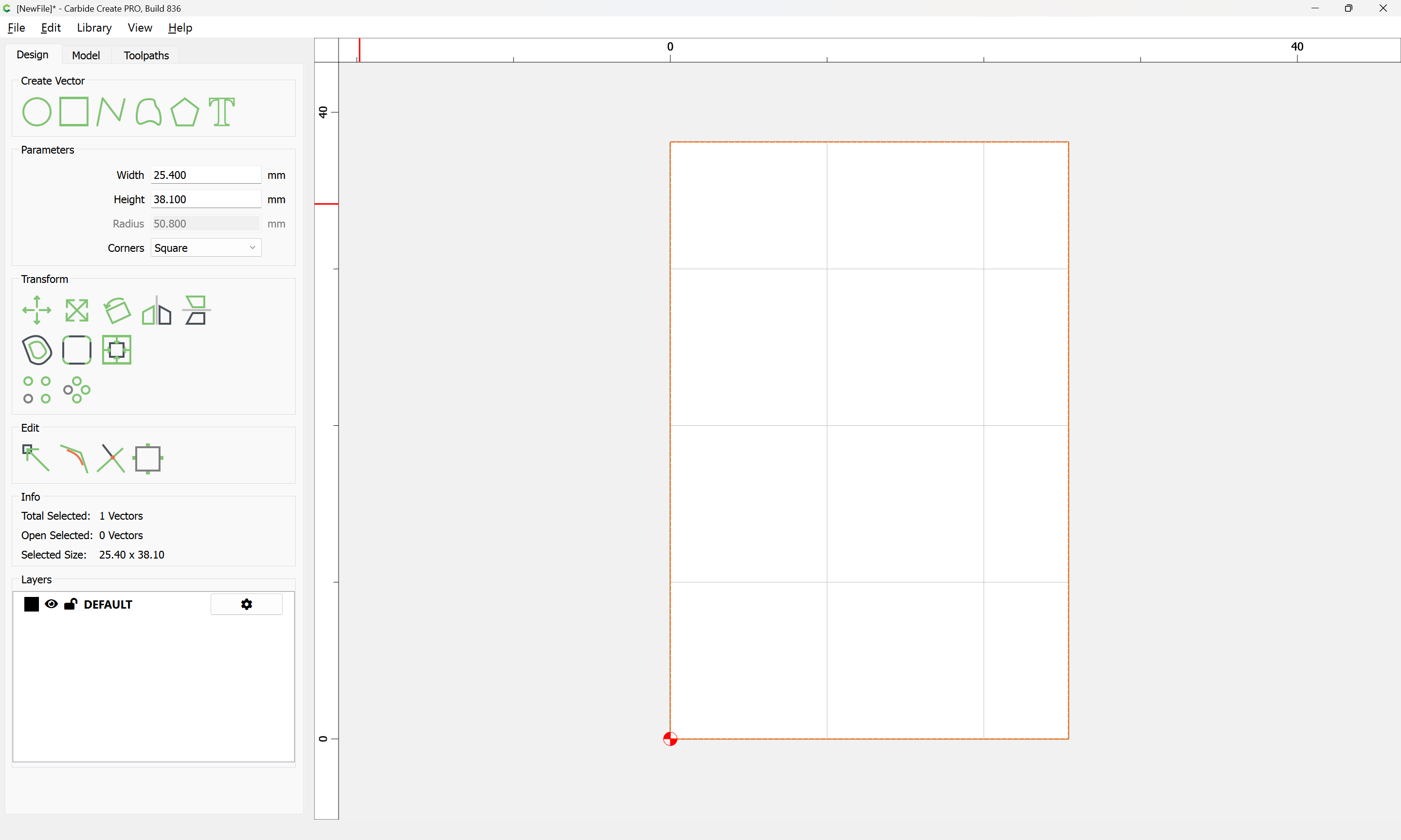
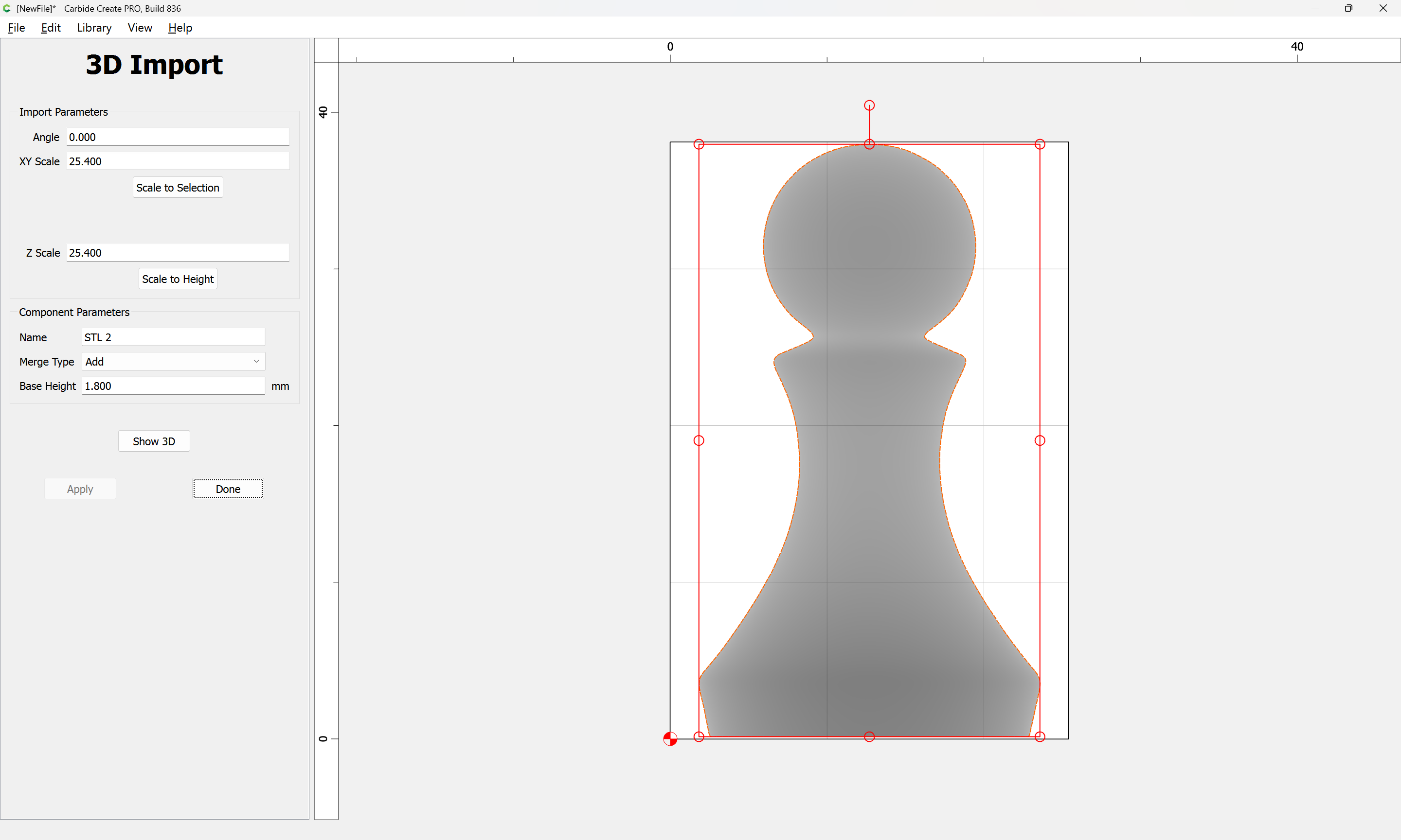
My stock is the correct size, 25mm x 25 mm, the object is scaled to that.
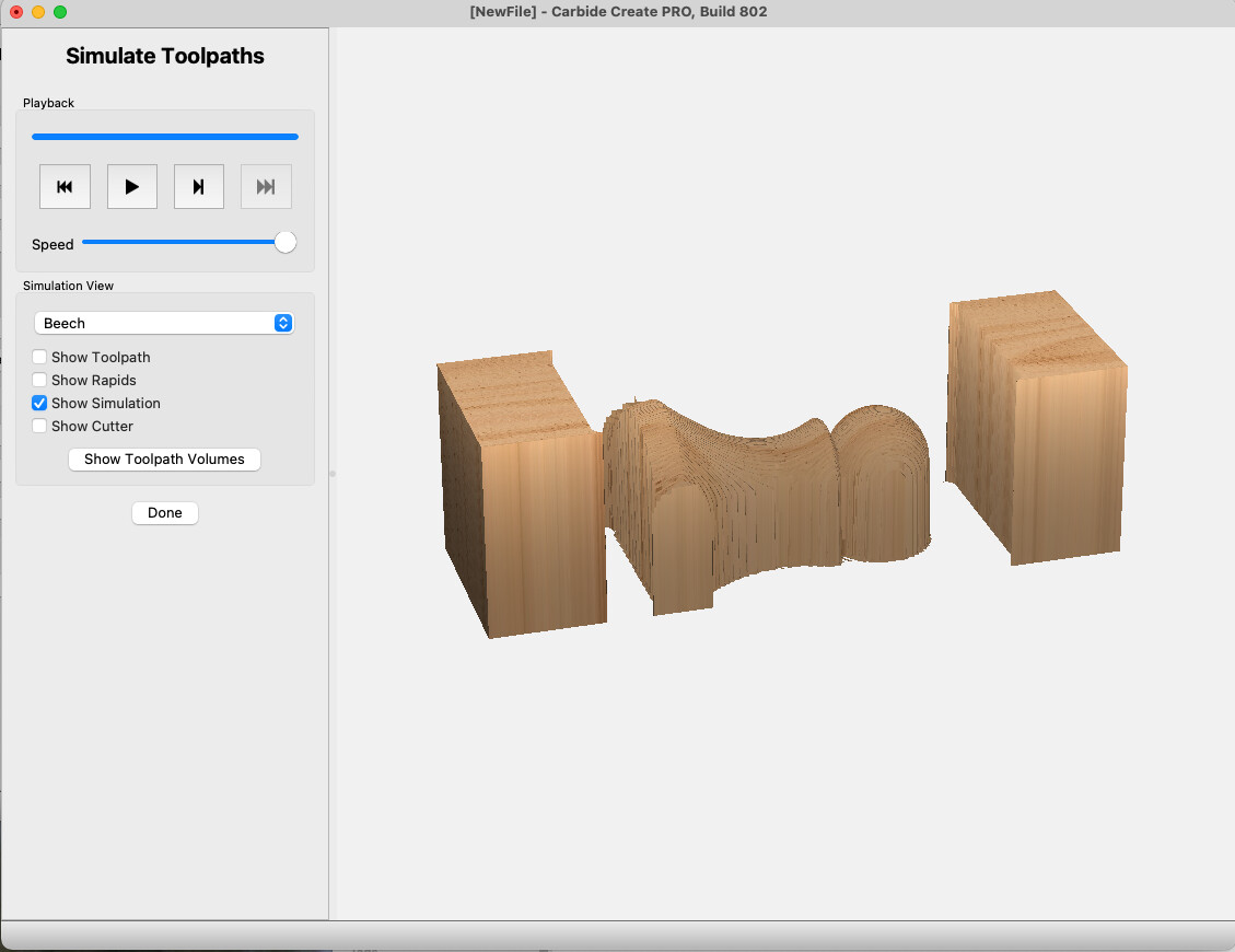
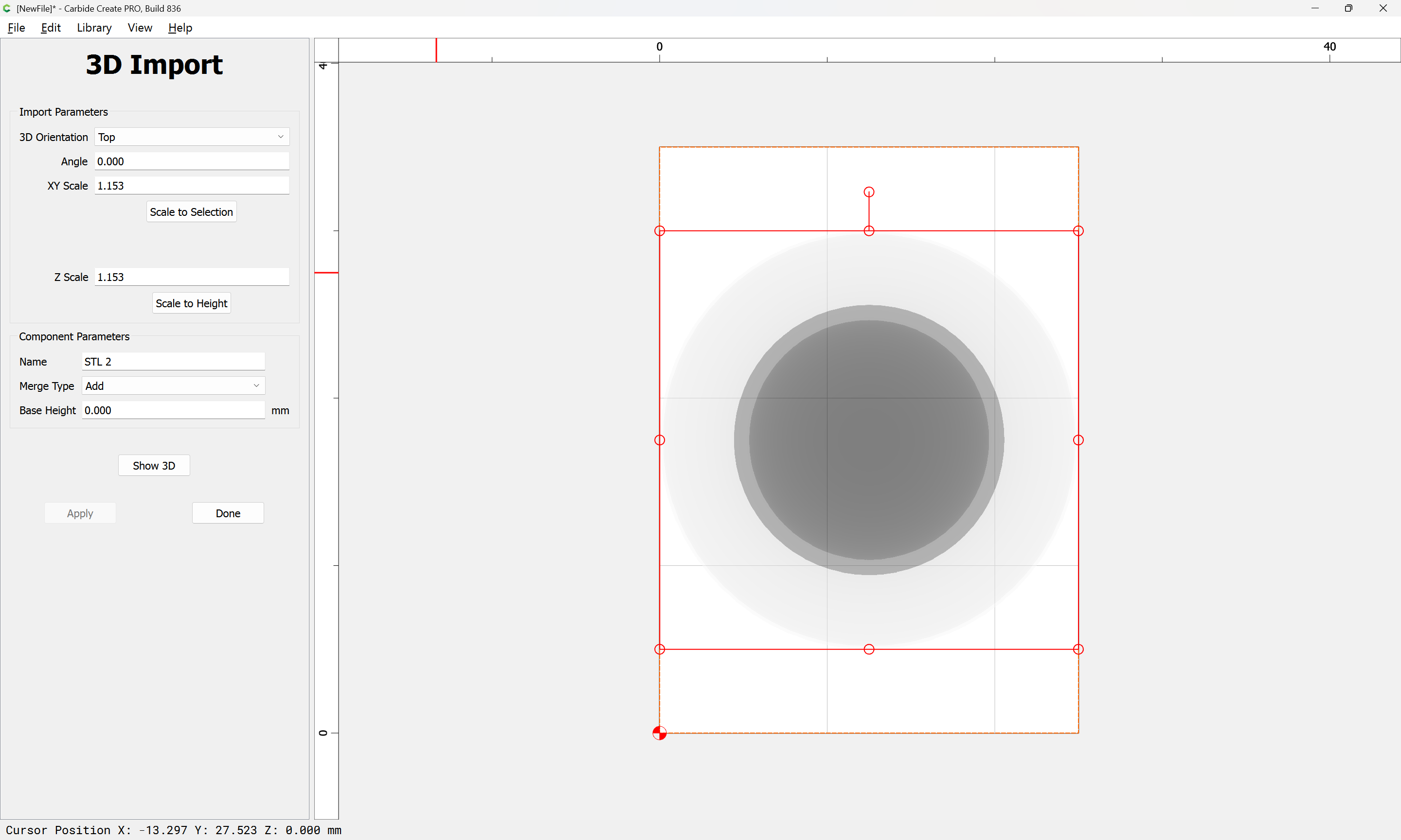
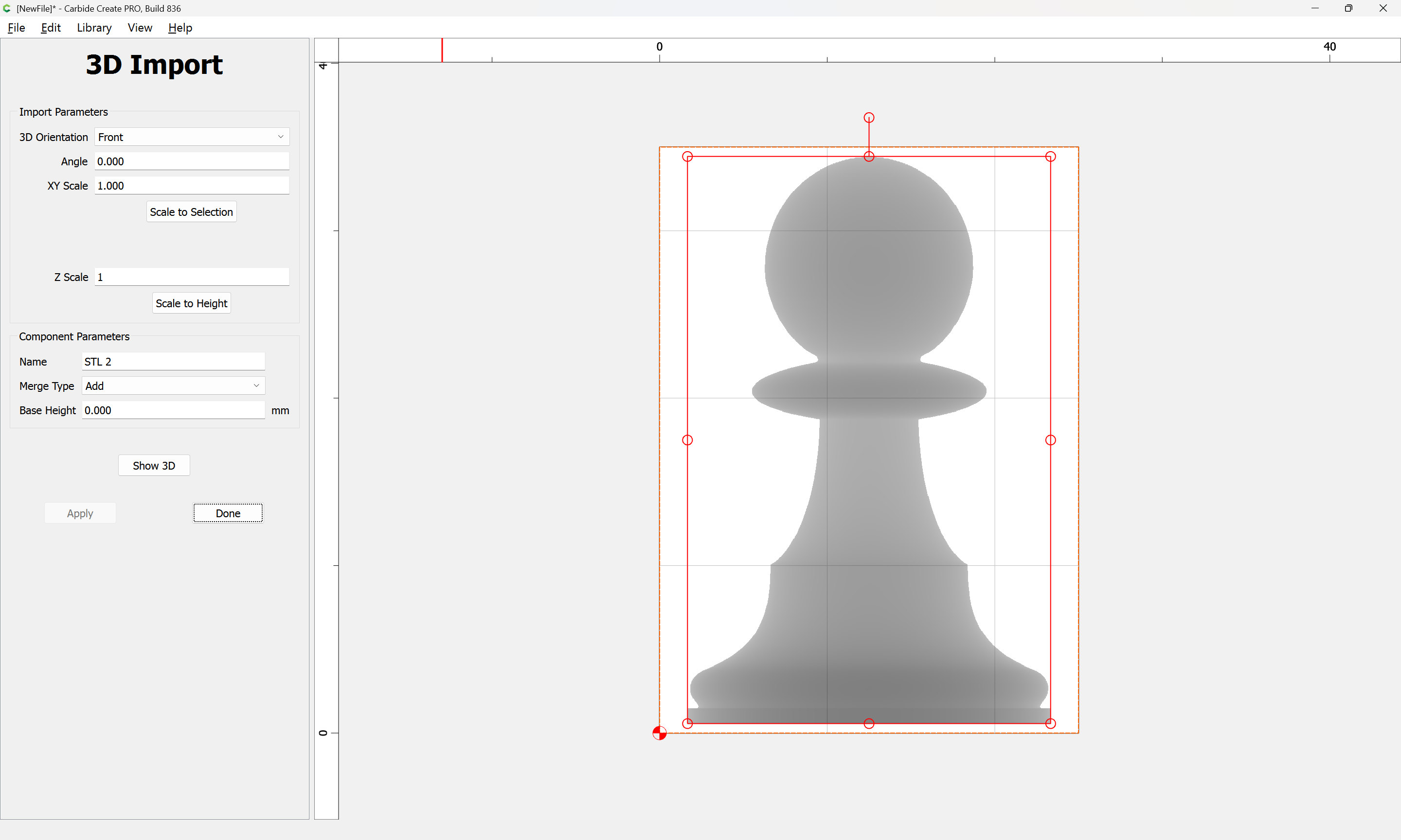
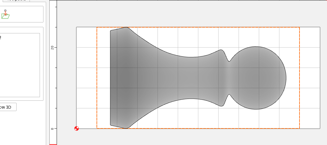
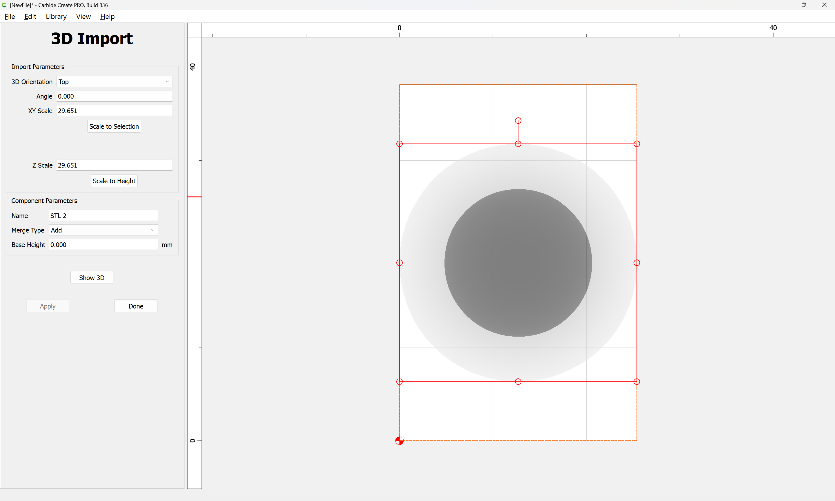
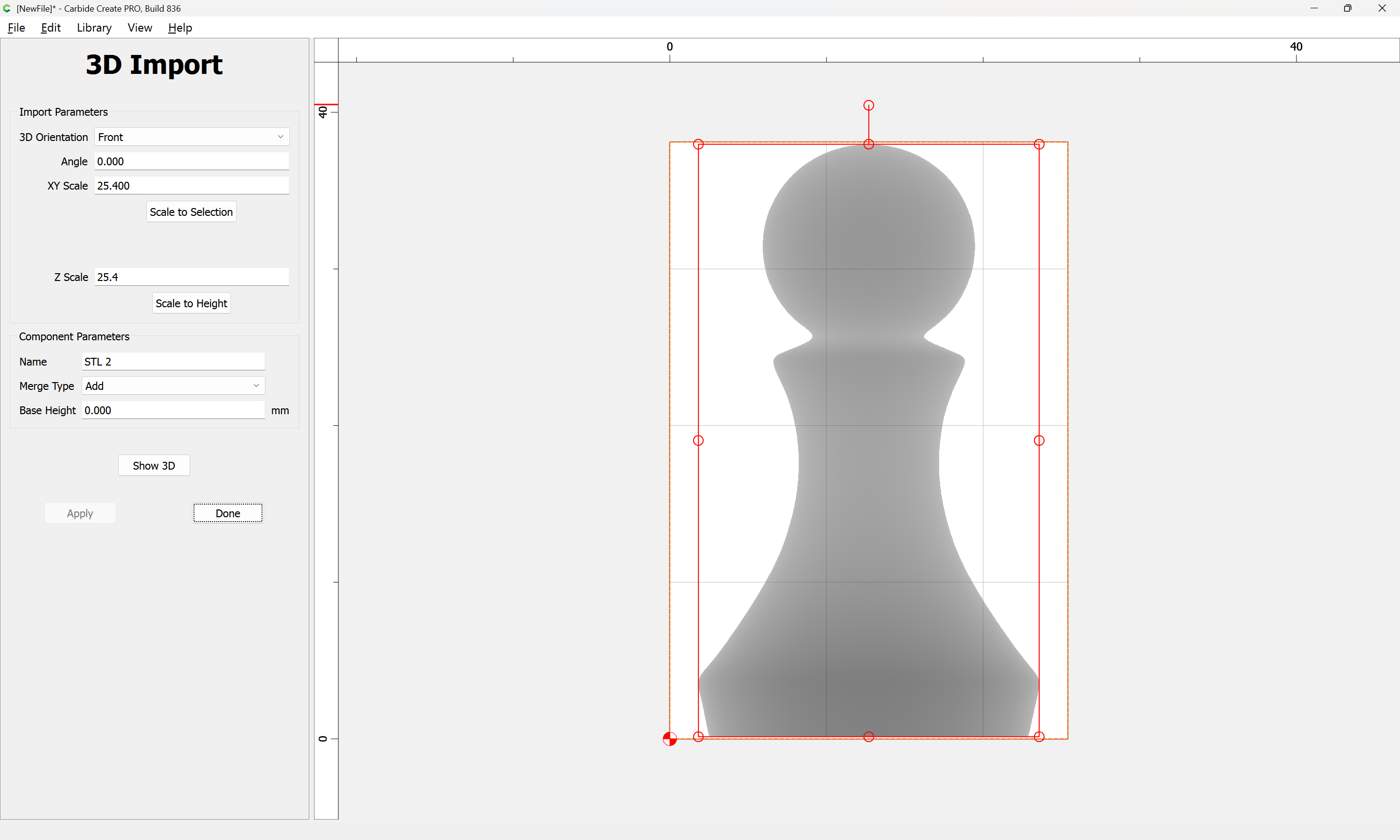
Why is is starting so deep? How do I reduce the depth it starts at using the import parameters?
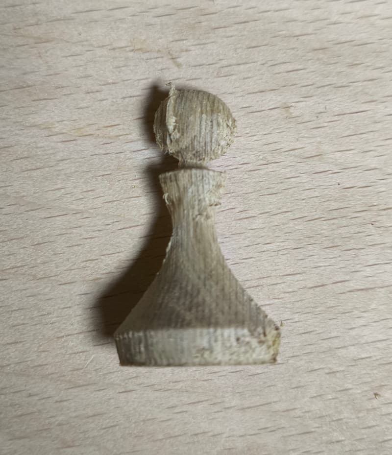
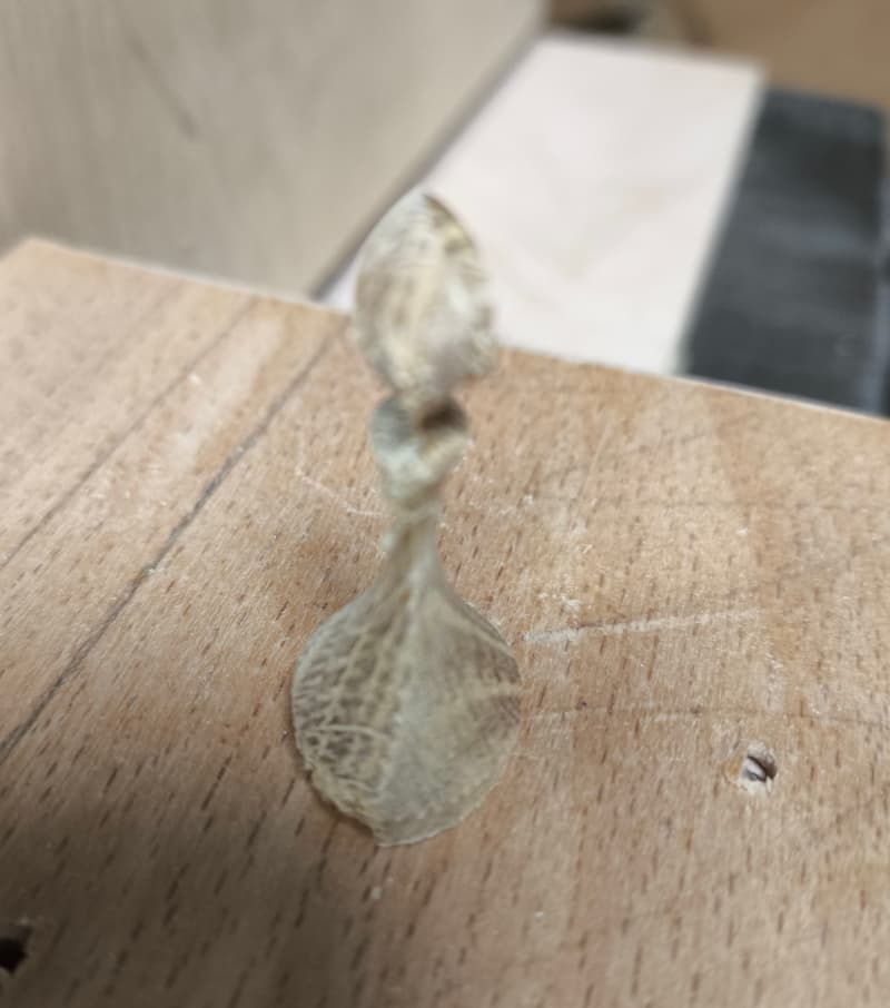
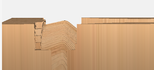
Looking at the produced item, the start depth is the problem, becuse the width (skinny side) is 15mm, 6mm out from what it should be in final form (21mm), 3mm on each side which is about how far it mills into the surface before it starts cutting the shape. Are you saying my 25mm sqare stock needs to start off at 31mm and if so, why? Why is the starting depth +3mm ?
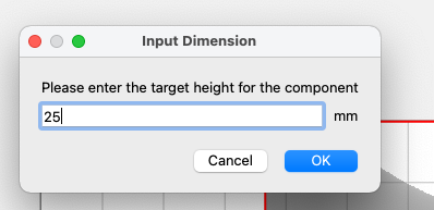
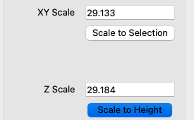
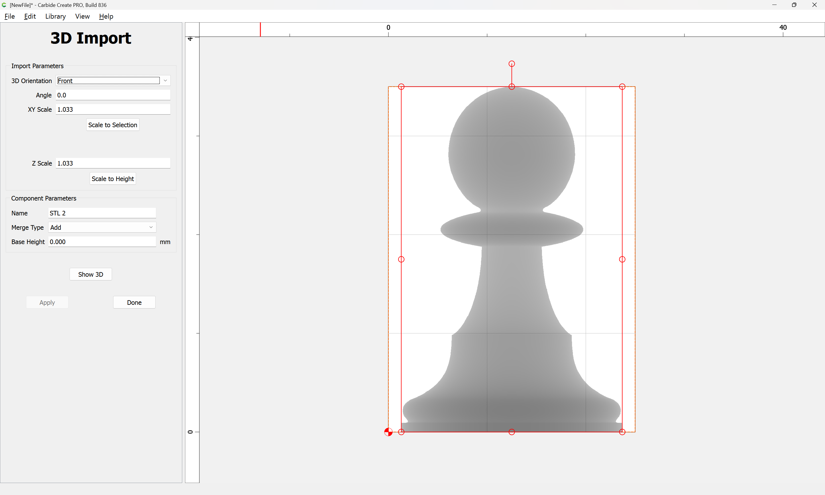
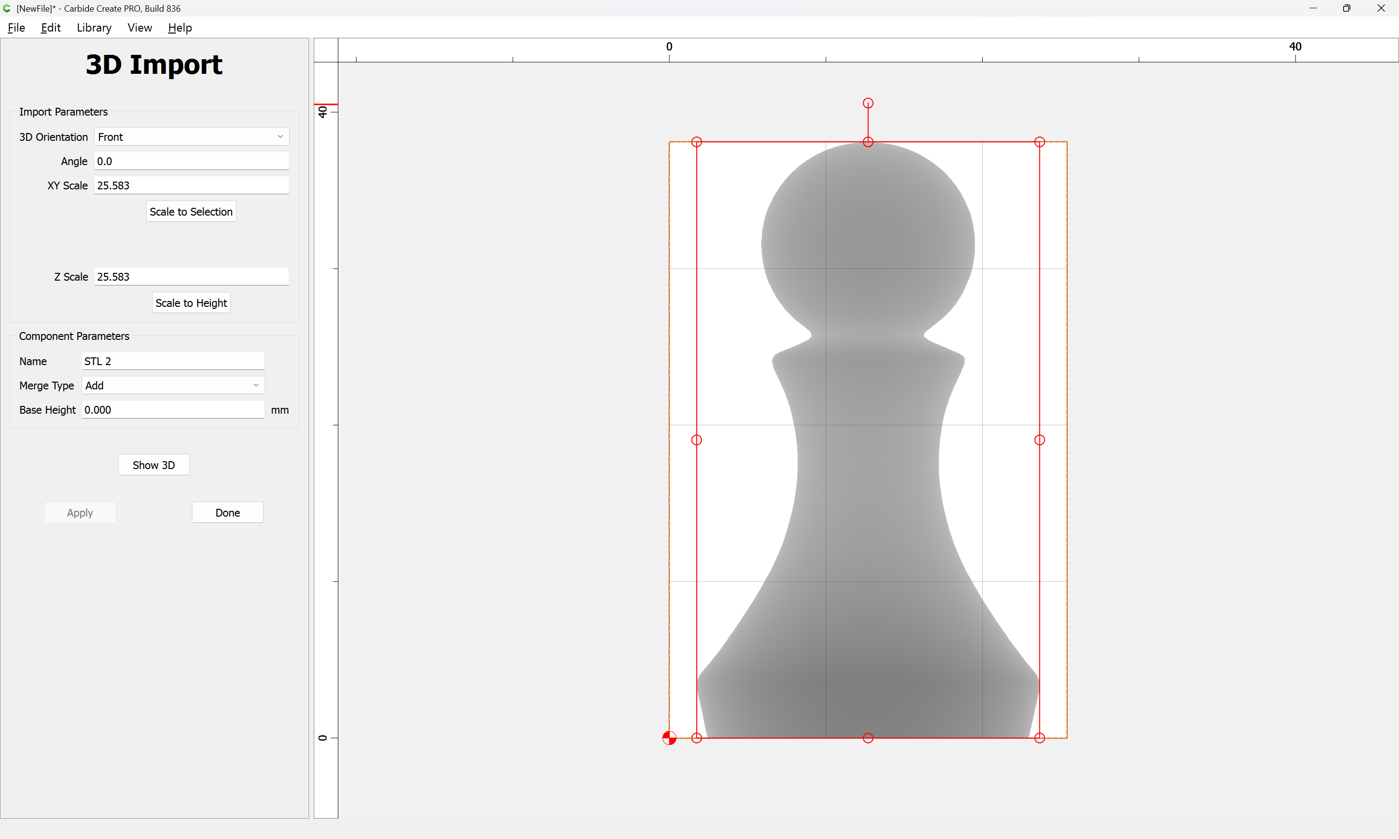
If you click, “Scale to Height”, what is the height? It should be 25mm, and whatever that converts the Z Scale to, the XY scale should probably be the same.
The “25” you’re seeing in the Scale fields is 25x (the original size).
For what is worth, I used these exact same files to make chess pieces in walnut and maple. They all cut fine on my machine once I got my settings correct. The problem was that every piece would have required a lot of sanding and clean up to make them even half way presentable. Then I would have had to drill out the bottoms to make them weighted pieces as I originally planned. In the end, I decided to throw them away and bought a very high quality set on Amazon for $39. I instead spent my time and energy making really nice end grain chess boards for my grandsons. It was a good 3D learning experience but I couldn’t compete with even inexpensive commercial pieces.
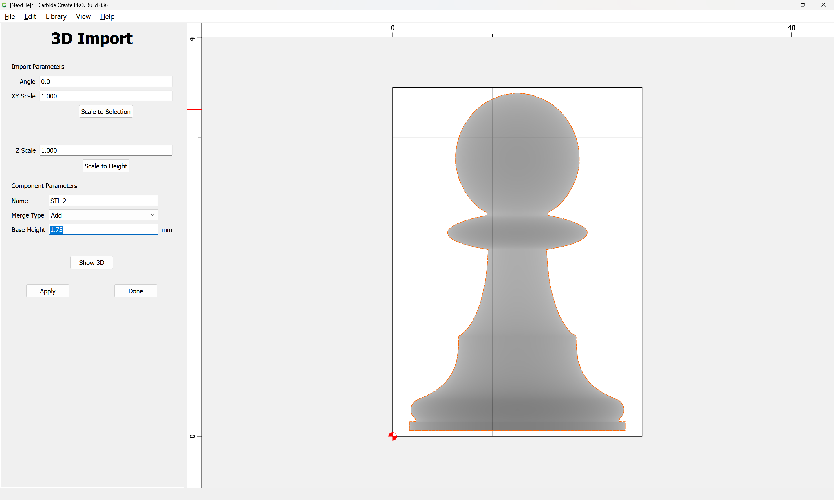
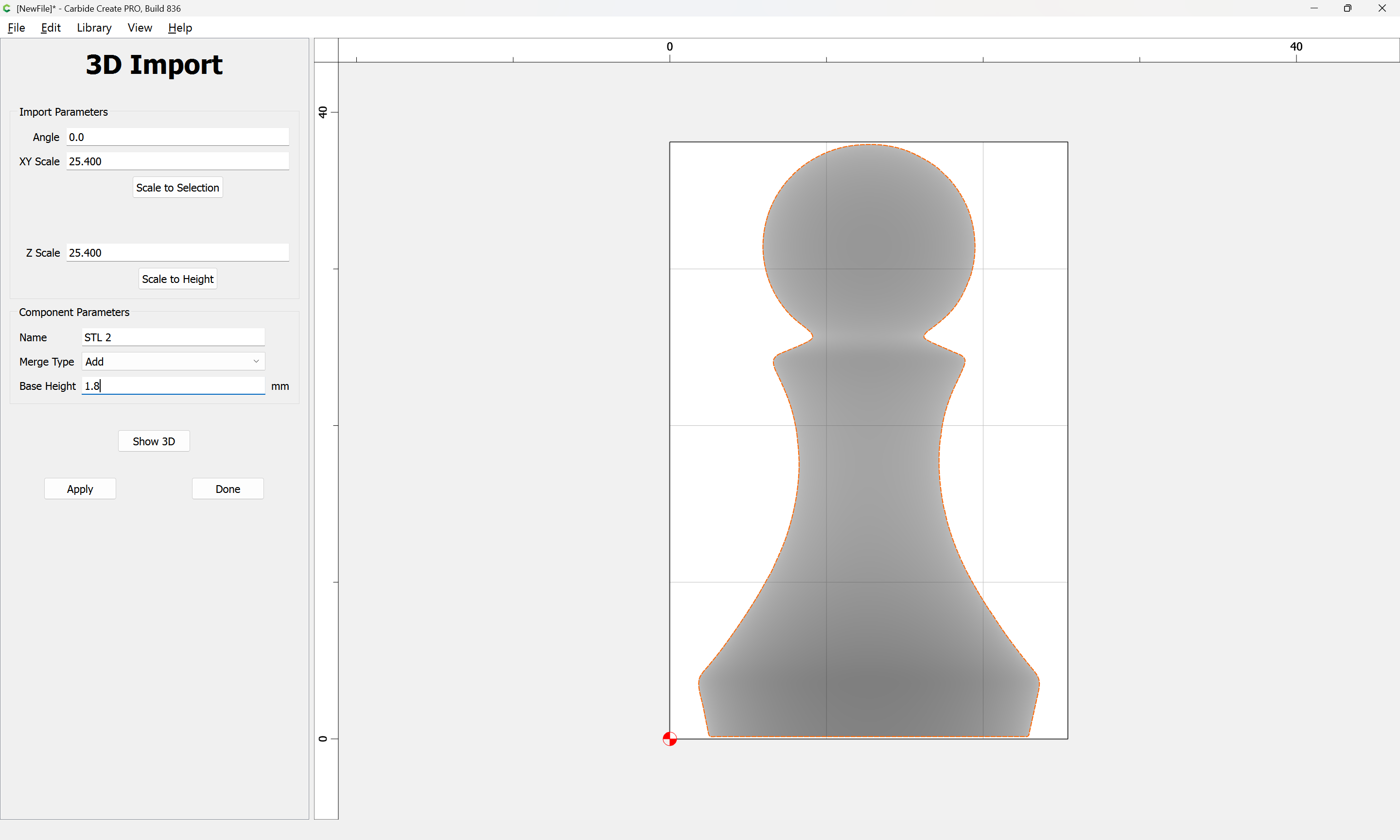
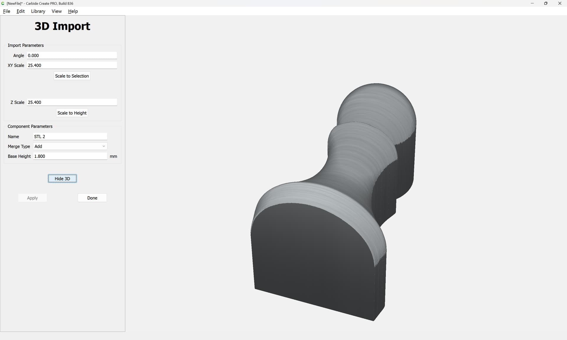
You can use the Base Height function to raise/lower the STL within the stock volume.
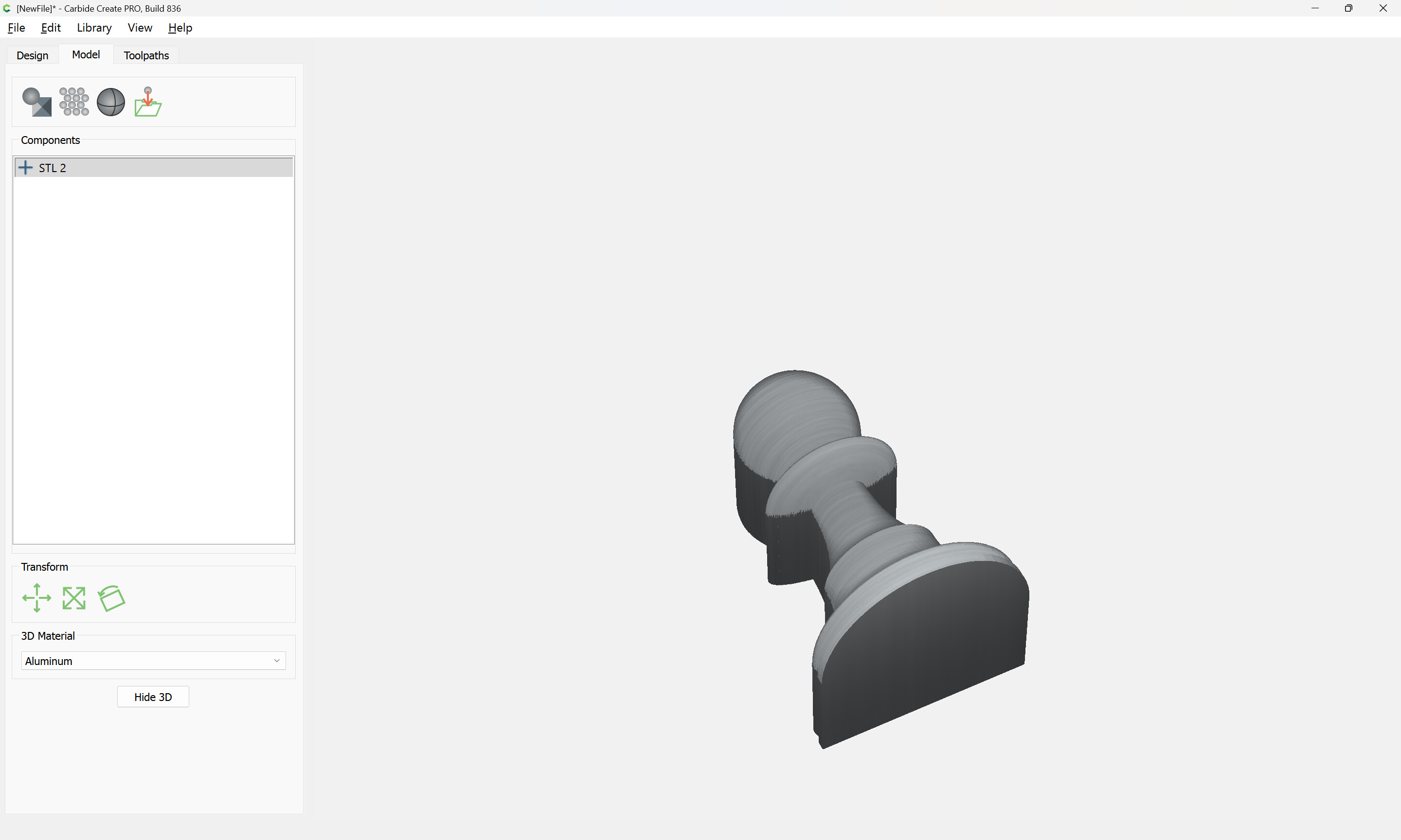
I would suggest creating a reference object in the modeler which you can set a height equal to the middle of your stock or the bottom of the STL or whatever you want.
Then when you look at the 3D render you’ll have a visual refernence. Once you get the chess piece height set right, then you can disable the reference object before making toolpath’s to run.
Or, you could make a Base rectangle that sets the bottom of the STL & would keep the toolpath from diving all the way down to the bottom of the stock. The toolpaths basically drive down to the Z-zero or stock bottom when they fall off a 3D mesh. So you have to create a platform under the chess piece to catch the toolpath.
Yes, I agree I could just buy some quality pieces, but I want to try it first. It’s a low cost, in terms of time to produce each part and for the initial outlay for the stls. I actually disgarded the old stl and picked up some much more rounded pieces which I prefer. I don’t mind the post processing much, this is part of a one off gift for someone close to me.
This is all in theory, I’ll have to test it tonight when I get to my workshop…
I’m not sure if I’m adding too many steps, but as I’d only really need to do this once per piece it’s not a huge amount of effort. Although I suspect I’d need to do it for each stock size I was going to work with.
The big step you need to do is to take note of the vertical position of the piece, then add to the Base Height so as to get it centered in the stock along Z.
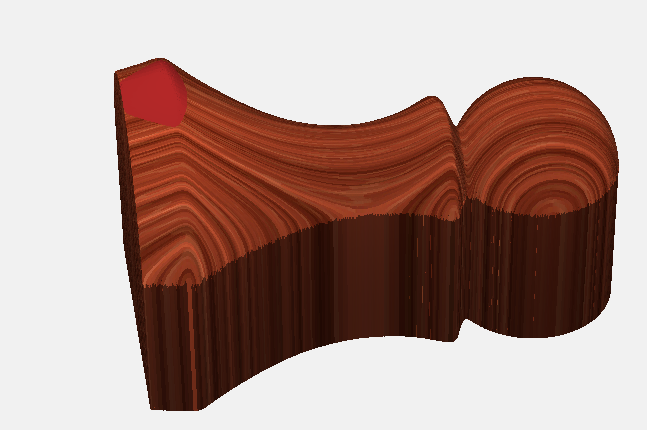
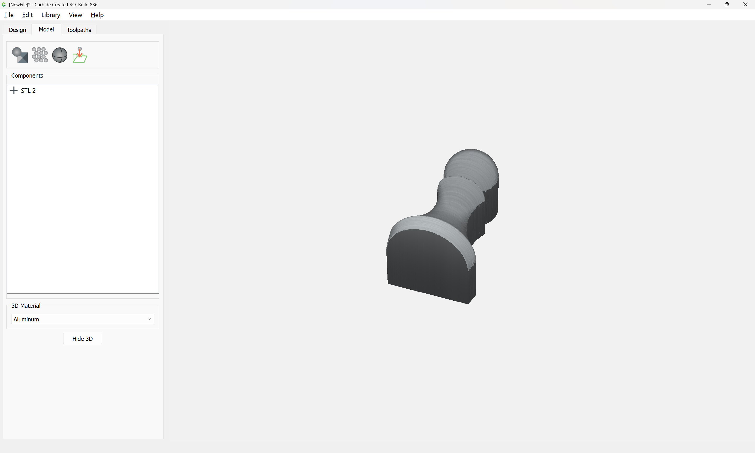
If I add even 1mm to the base height I start getting red on the 3D model, which I presume means it’s not going to cut that part because it’s out of bounds. Can the base height be negative?
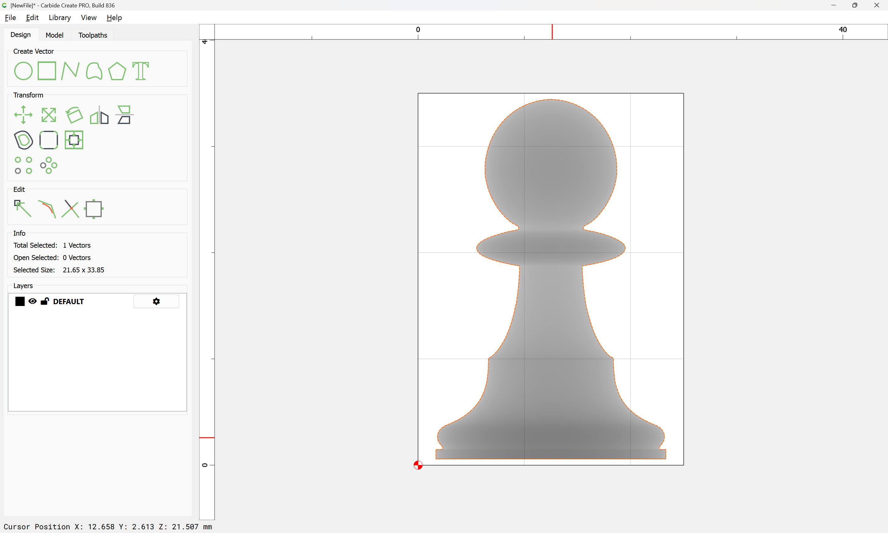
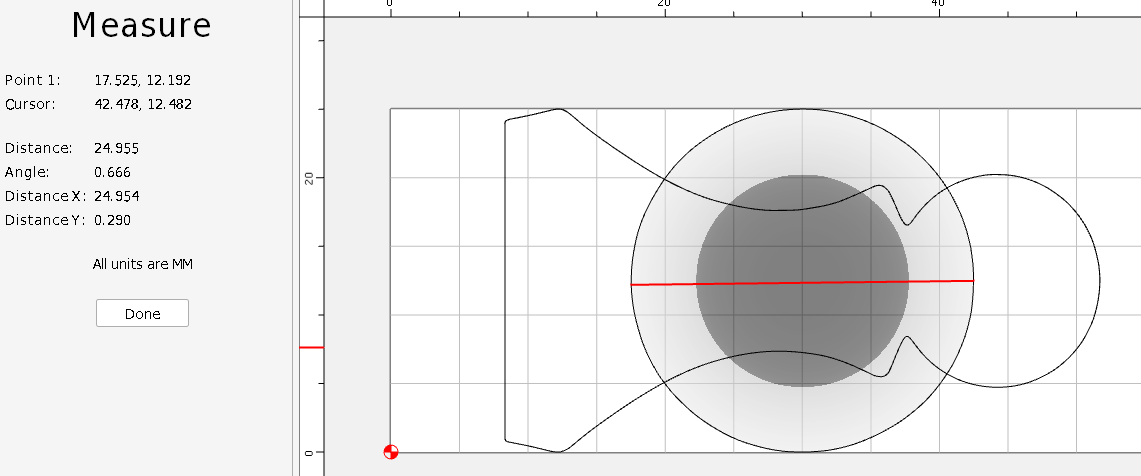
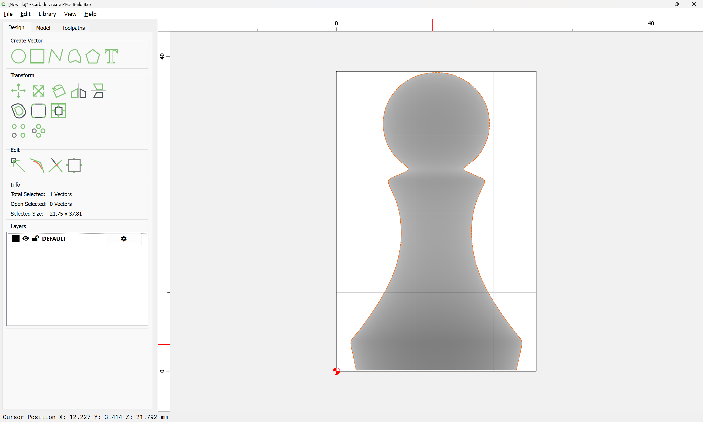
where we see that it is quite close to the expected 21.8mm height (check the Status bar which shows “Cursor Position” at the bottom — it also shows the Z-axis height of the 3D model at the cursor position)
We want the center to be at 12.7, so using half this thickness, (10.9) we need to add:
It should now work to cut both sides using this 3D model, and so long as the flip is accurate and the stock thickness/Z-axis height setting match up, the result should be as expected.
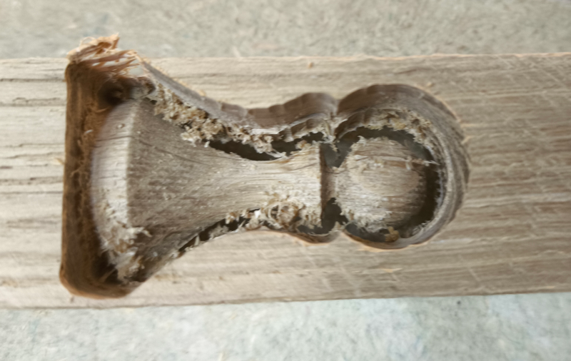
I bought the same stl pack, out of curiosity, did you ever get this to work fully? The issue I am running into is that when doing the finishing pass, my bit plunges into the work piece and jams.