Hi all!
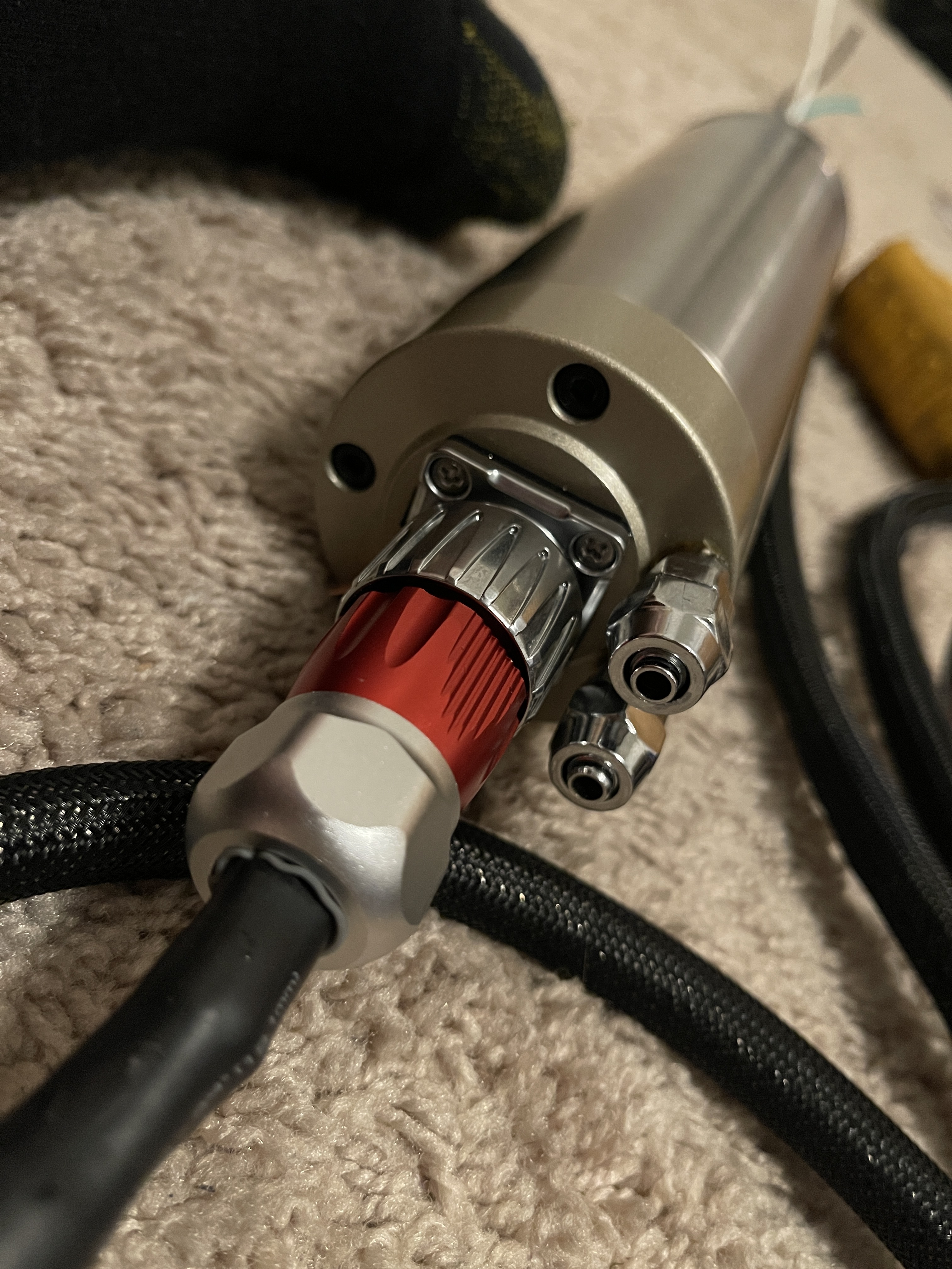
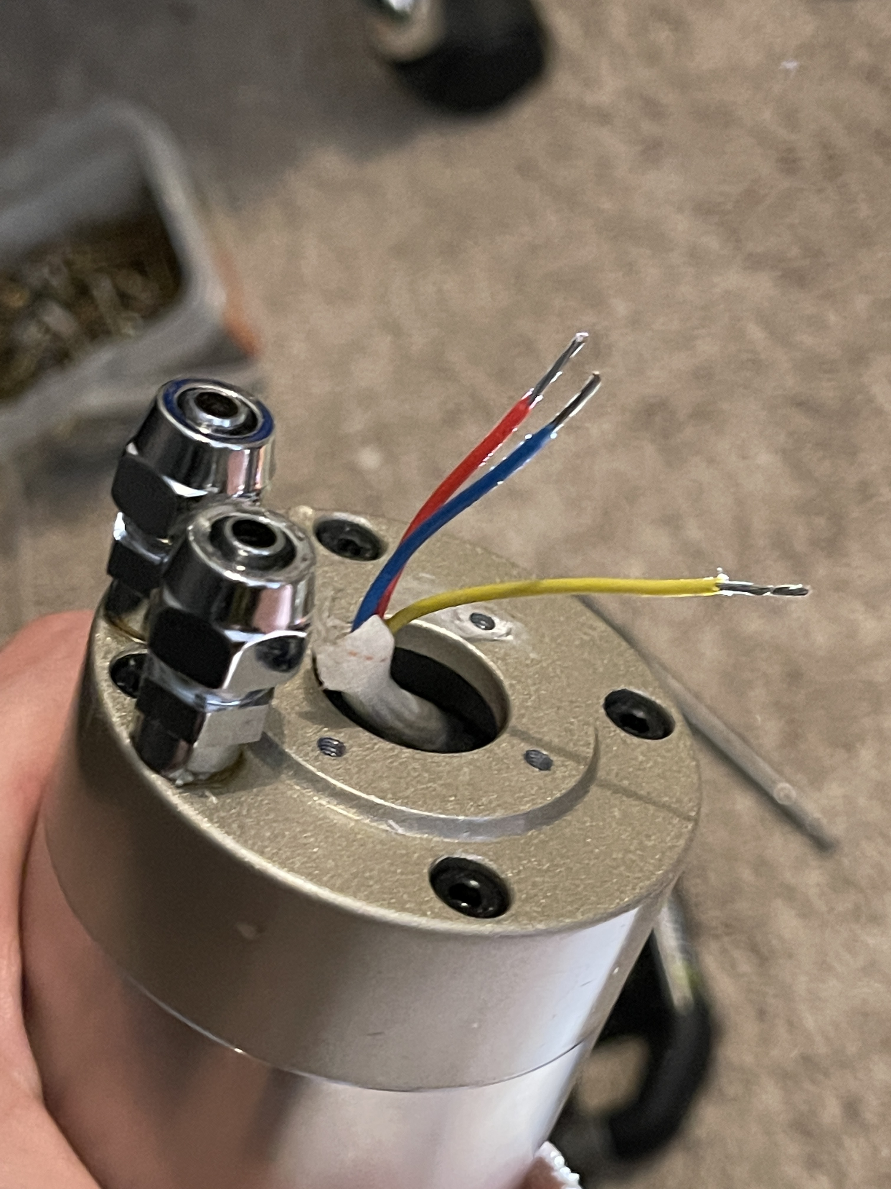
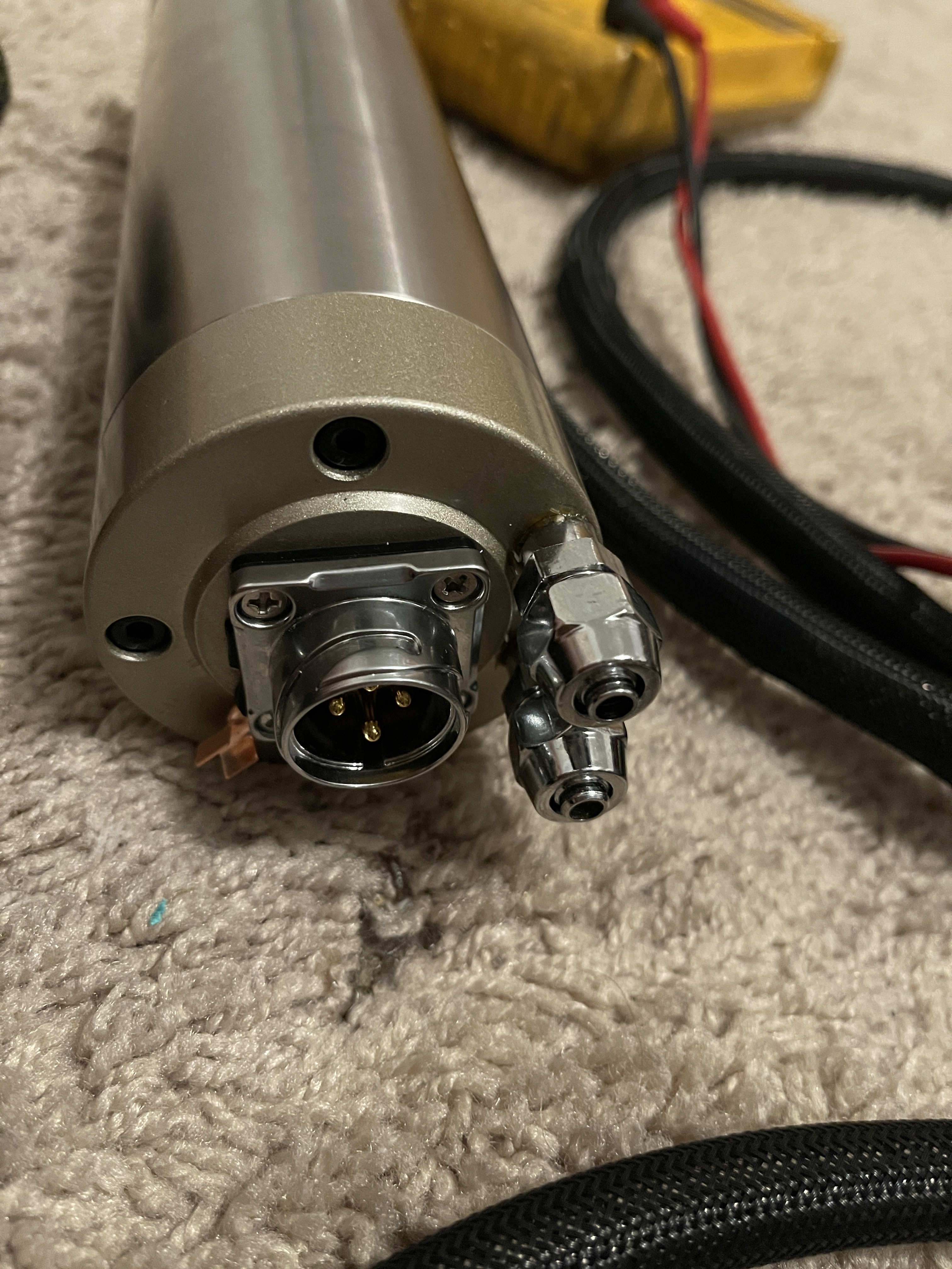
I installed a 800w water cooled huanyang spindle and a 1500w Huanyang VFD. Here are the current parameters
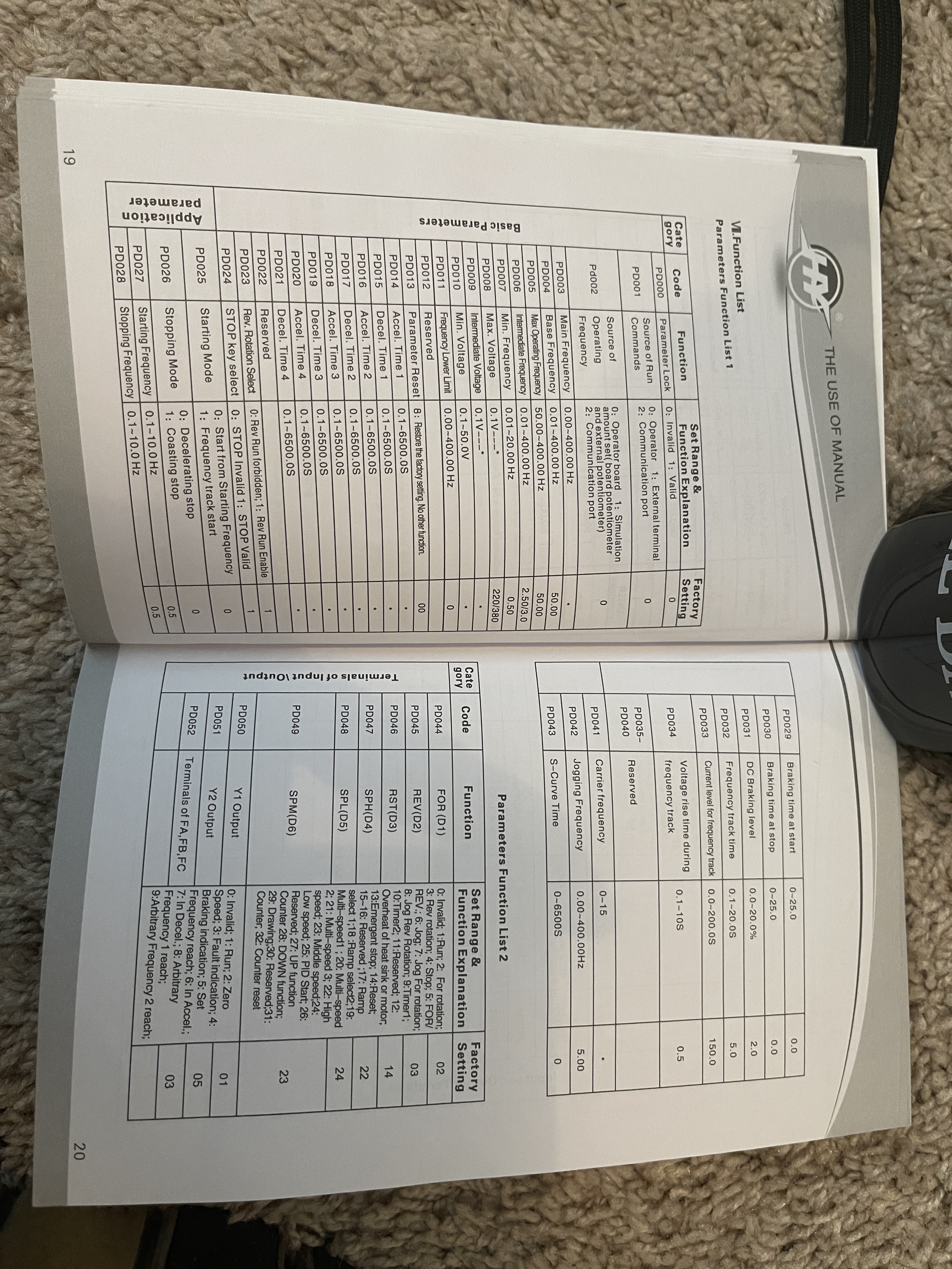
PD000 = 0
PD001 = 0
PD002 = 1 (potentiometer on board controls the frequency)
PD003 = 120.00 Hz
PD004 = 400.00 Hz
PD005 = 400.00 Hz
PD006 = 2.50
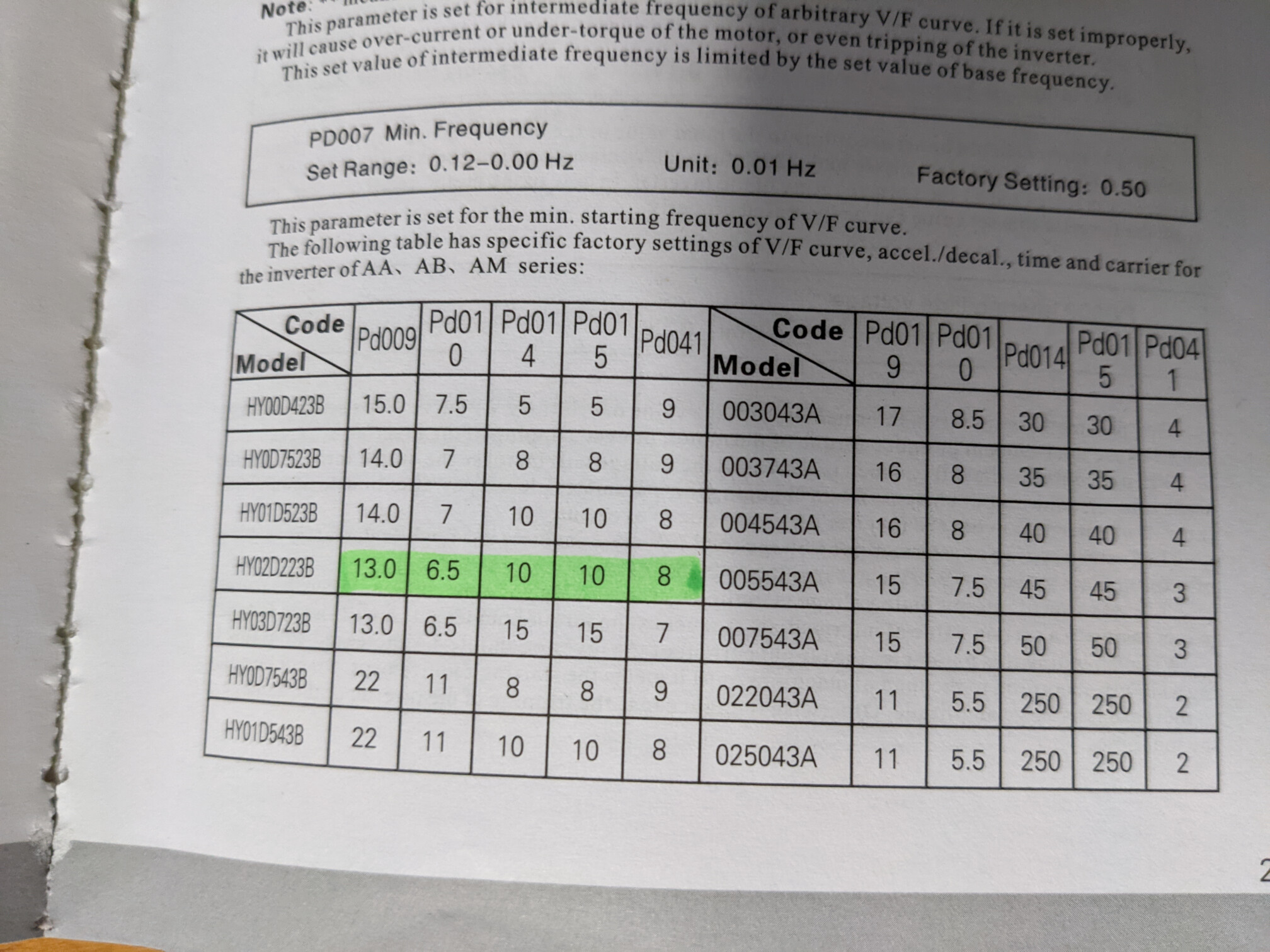
PD007 = 0.5
PD008 = 110V
PD009 = 15
PD010 = 8.0
PD011 = 100.00
PD014 = 12 seconds (Acceleration time)
PD015 = 12 seconds (deceleration time)
PD070 = 1
PD 071 = 20
PD072 = 50
PD073 = 100.00
PD074 = 0
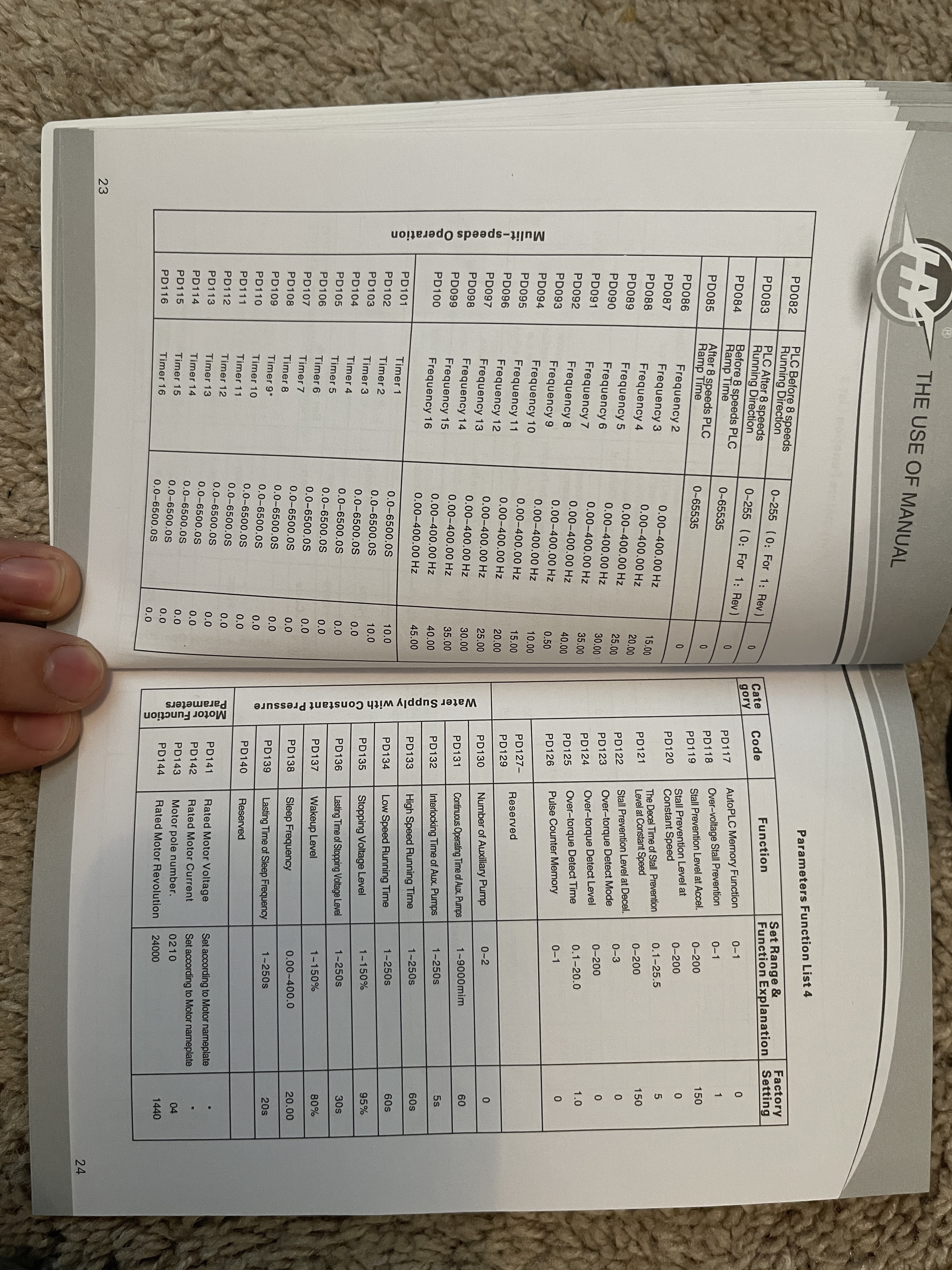
PD141 = 110
PD142 = 4.0 amps (guide says 3.7 and the spindle is rated for 5)
PD143 = 2 (number of poles).
PD144 = 3000hz (intermediate frequency)
110v Mains, 110v spindle. When I turn it in it spins slowly and I get a E.Ao.A error which is guess is an over current error based on what I found? I tried starting it a few times and each time the spindle spins at ~100 rpm and stops shortly after.
Should PD003 be set to 400 since that’s the spindle frequency?
Any advice?
EDIT
so upon watching a YouTube video of someone with the same VFD and also running an 800w spindle (air cooled instead) I found some useful knowledge.
PD009 for me is set to 15. it doesn’t work. the gentlemen in the review said 15 didn’t work for him either and he set it to 7.50
I changed this and the VFD blew a 15a fuse on my little variable speed control box ( I set it to “full” so the VFD gets the full 120v im simply using this box as it has a fuse built in). as soon as I hit “run” it immediately blew the fuse.
The one thing I didn’t change is the Minimum Voltage. I set mine (PD010) to 8, and the review says 4. If I changed the intermediate voltage but leave the minimum voltage at 8, will that damage anything? should I change PD010 to 4?
Luckily there’s no smoke or the smell of burning electronics!
Sad boi hours