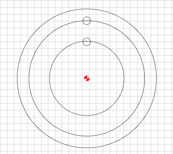
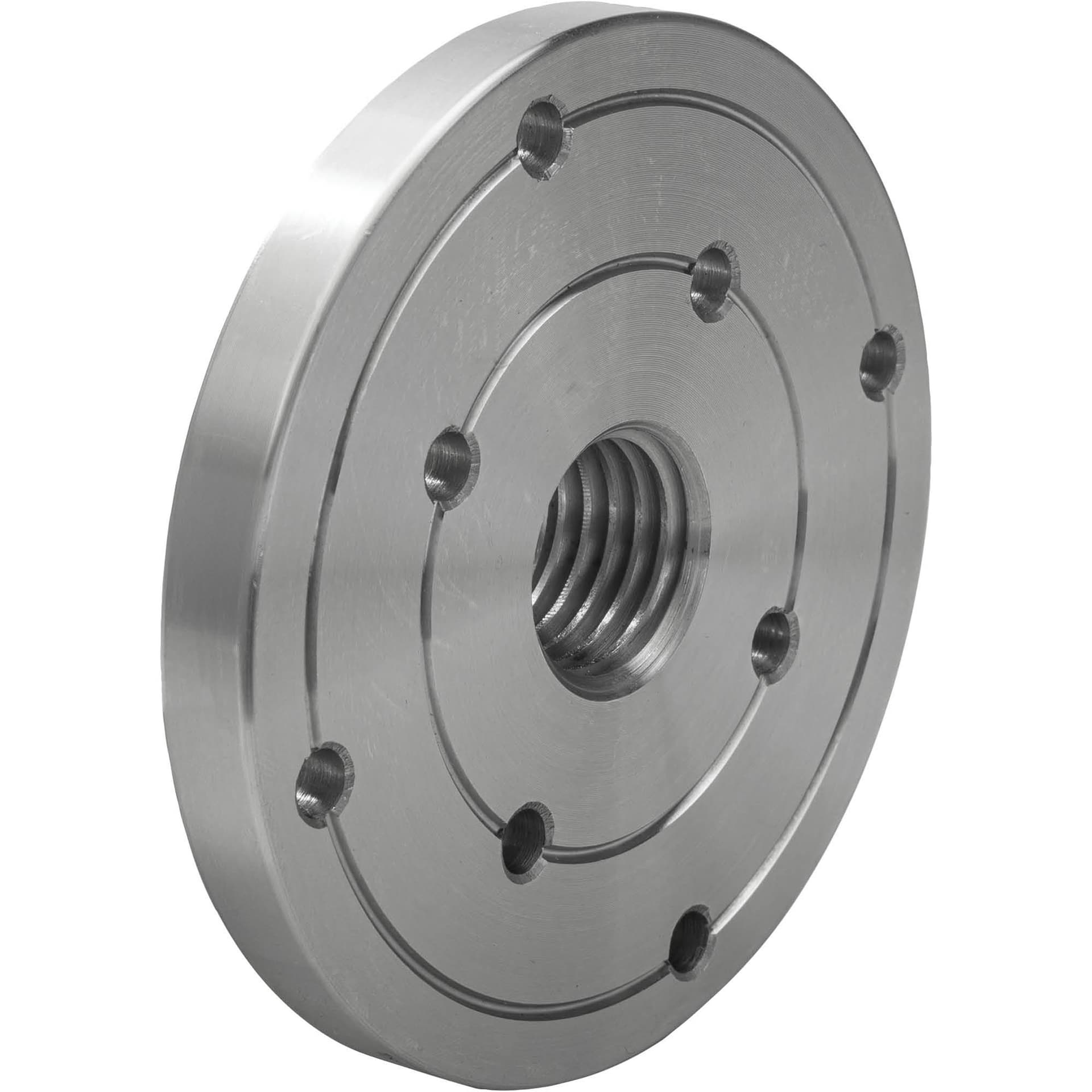
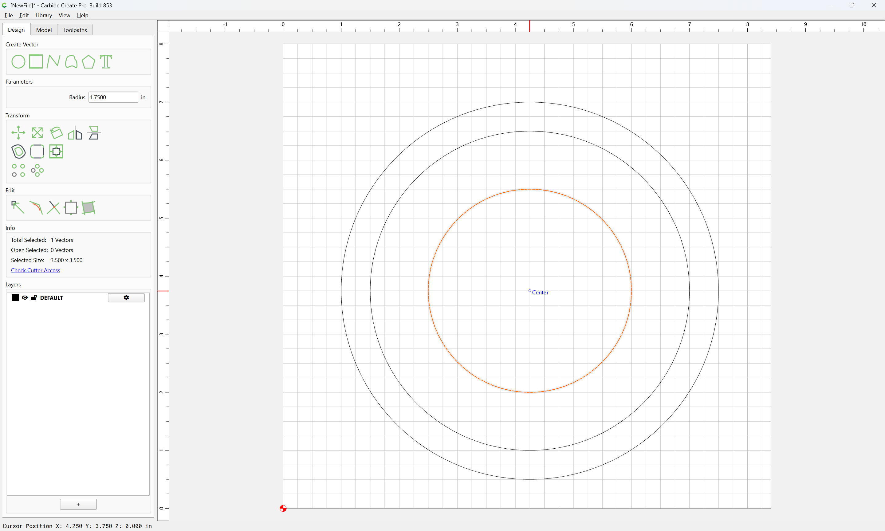
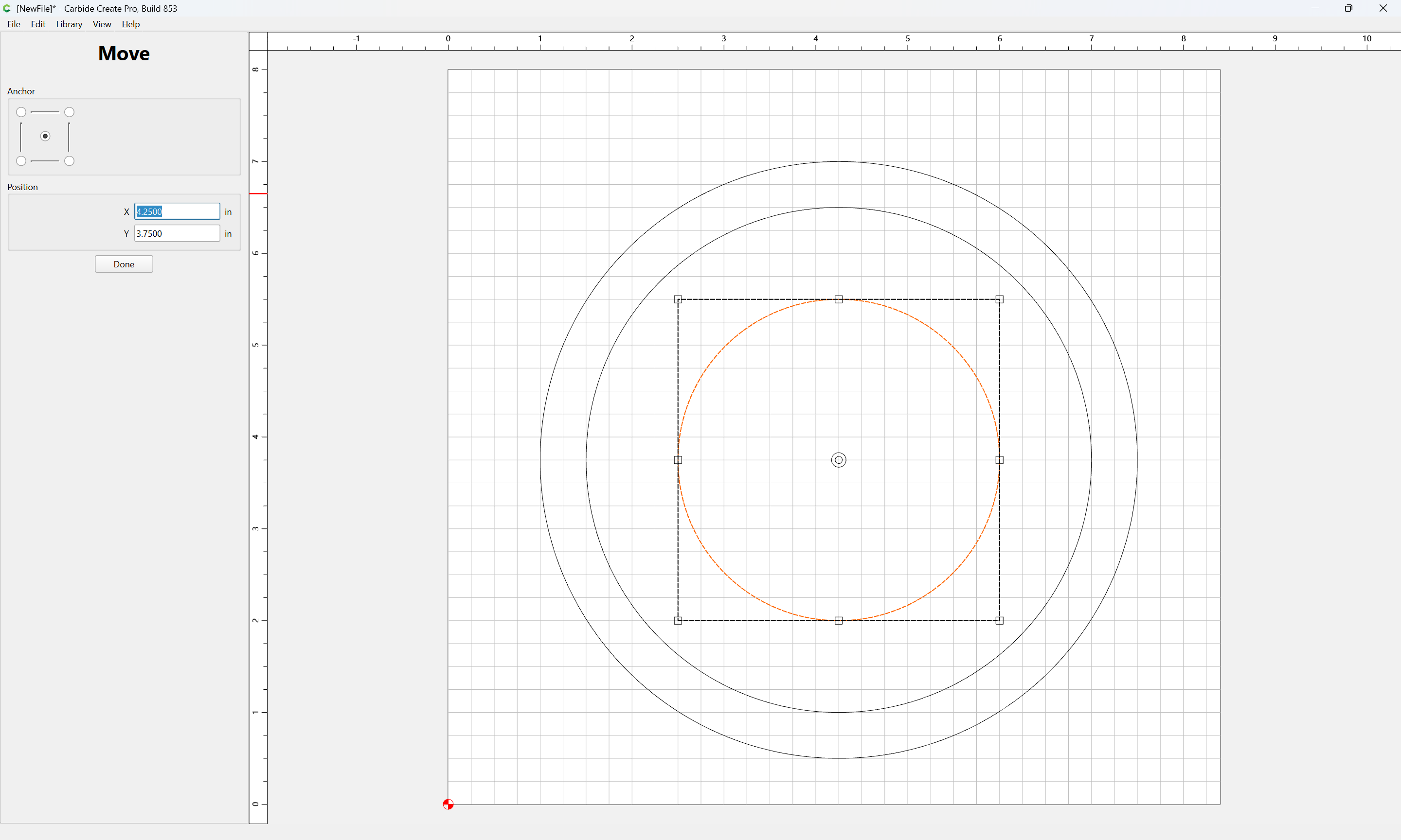
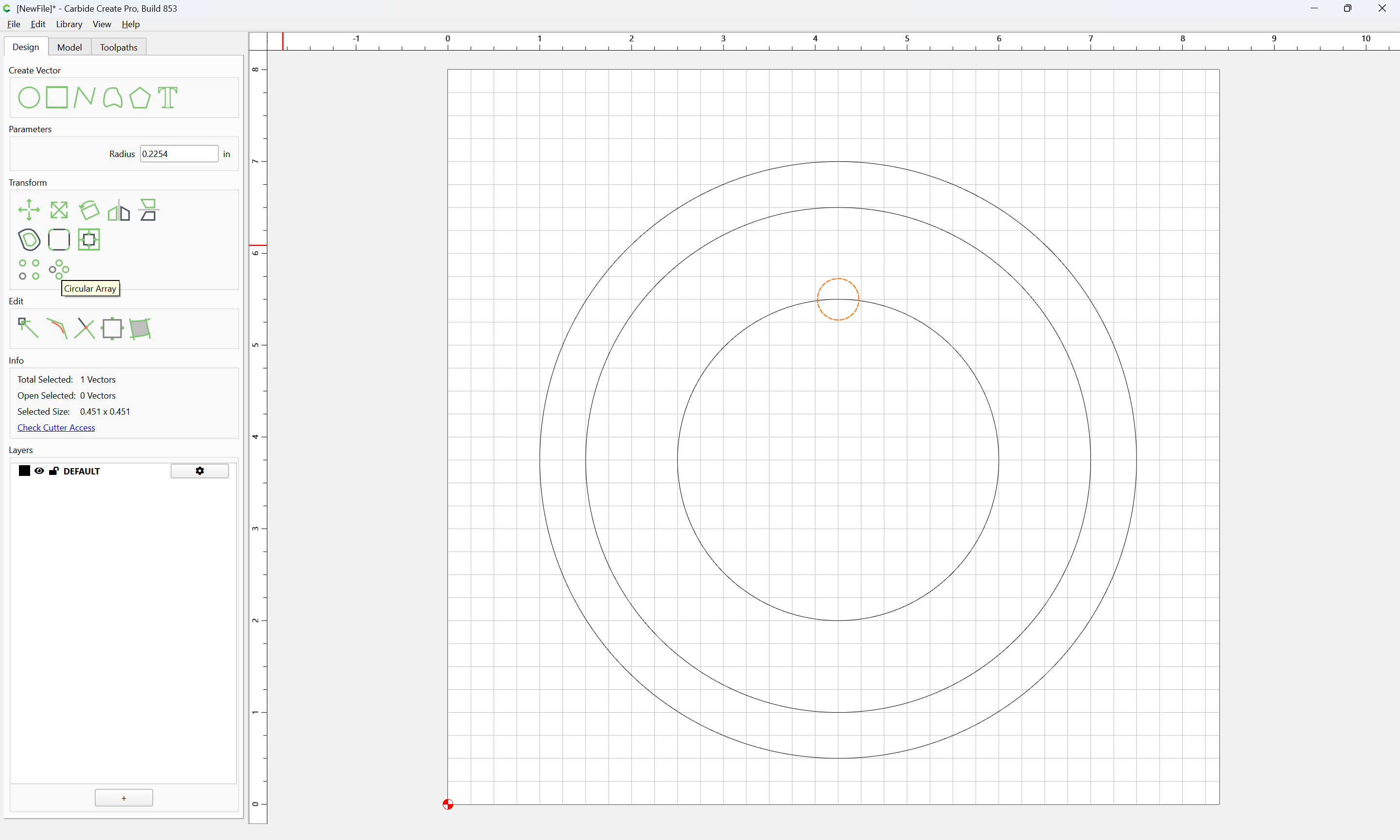
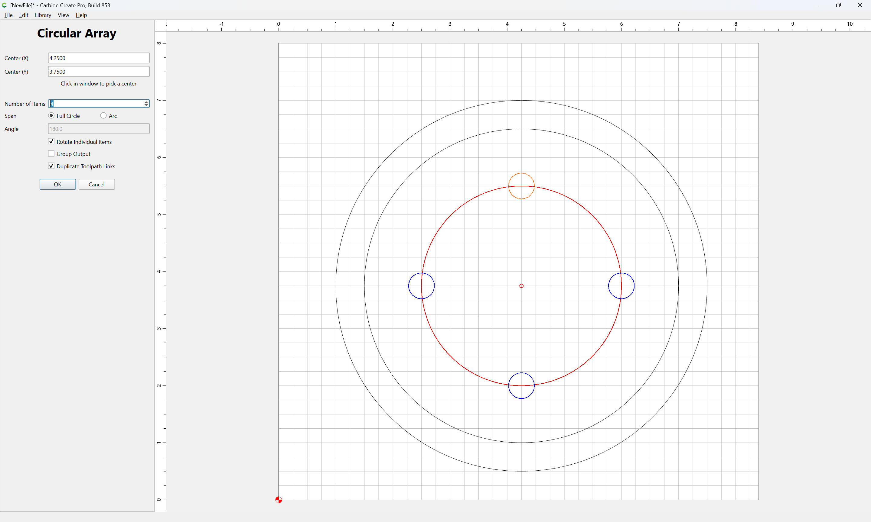
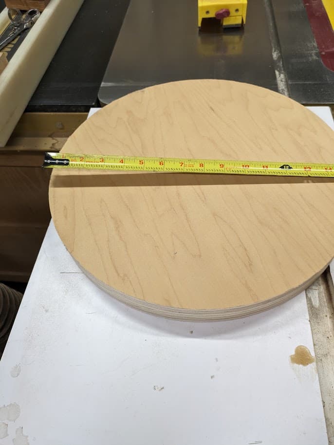
I created the circular object with two rings inside it. The rings are the diameter of rings on a face plate for my lathe. I am going to create a 15" disk and have the face plate in the center and machine the 6 holes on each of the two inner rings.
The inner ring is 1.071" radius and the outer one is 1.661" radius. I want a 0.1120" radius hole evenly spaced for 6 holes.
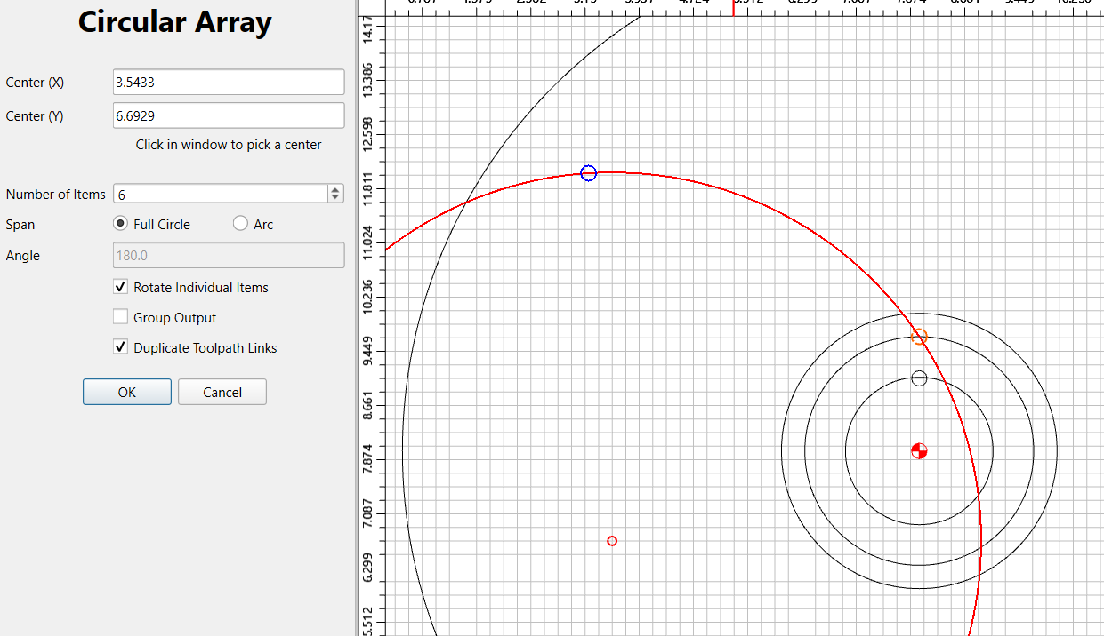
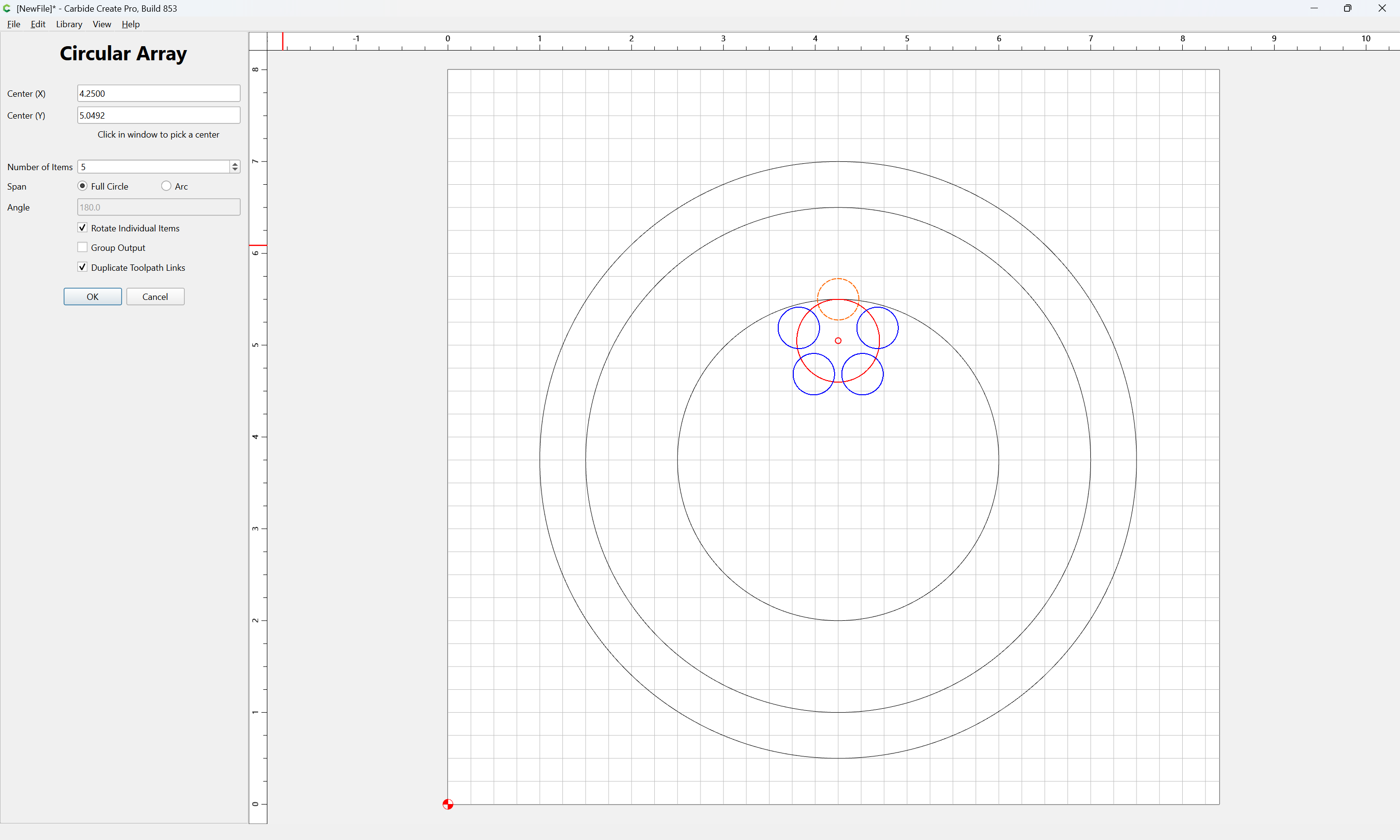
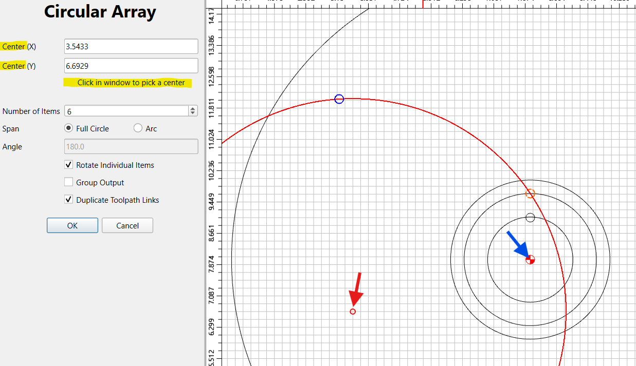
What I am not understand is the X and Y positions in the circular array tool. I pick the 0.1120 circle and I get a circle with 6 circles but I cannot figure out how to have those 6 holes around the 1.071" or the 1.661" radius circles.
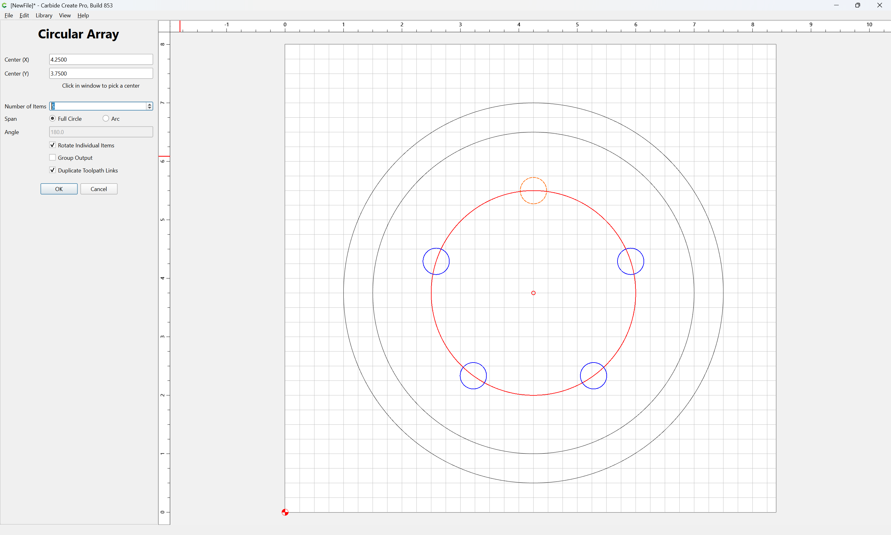
The current array center (Red arrow) is off to the side. Select the center of one of the larger circles to set the center for the array (Blue arrow). Make sure the tooltip on the cursor says “Center” rather than “Grid” or “Node”
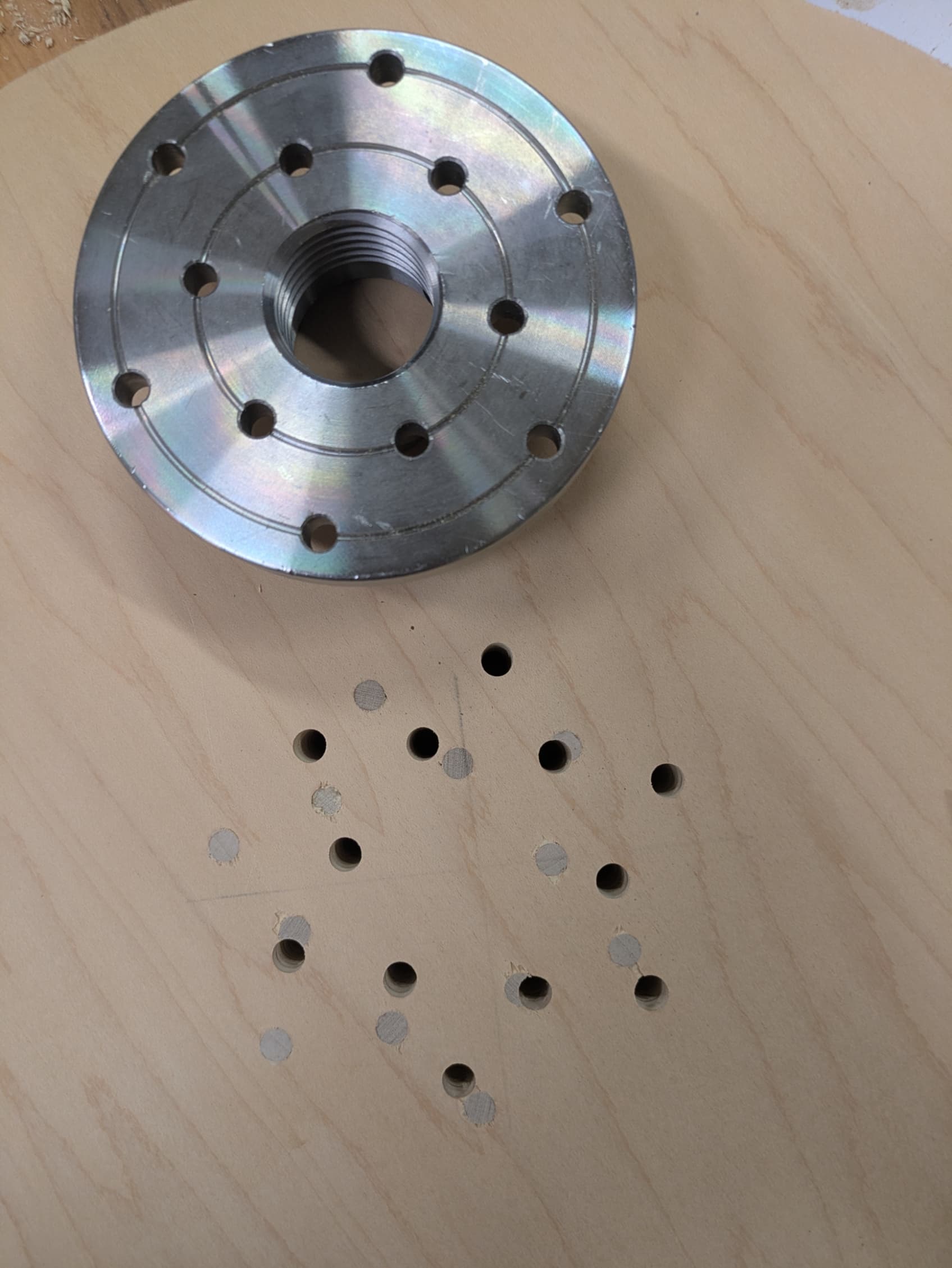
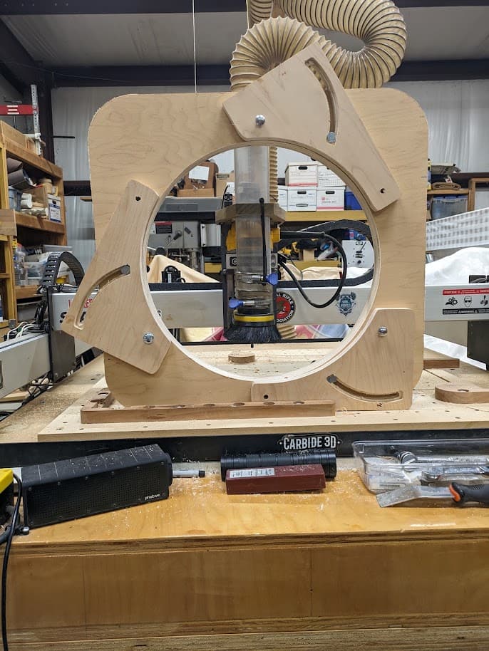
I got my problem figured out thanks to @WillAdams and @Tod1d . However I made a mistake. The plywood I used to make my lathe sanding disk already had a center marked on it. I had this left over from a steady rest I had made and assumed the X was the center and never checked it. Well it was not the center. So I glued 1/4" dowels into the wrong holes and recut the project. Now it is correct. Sometimes you are your own worse enemy. It was an easy fix and a fast cut.