Looking at this file file from support Resolving out of bounds errors - #2 by WillAdams , it seems like Create Pro should clip the max height of a 3D finishing toolpath to the top of stock, instead of letting it follow the surface way out of the stock material.
Can any Create Pro folks come up with a good reason not to do this?
due to discrepancies in stock thickness, I can imagine cases where I would not want the 3D path cropped/clipped right at the stock surface. I’ve seen 3/4" stock anywhere from 0.690 - almost 0.800.
If I’m intentionally allowing the 3D shape to extend above the stock, that’s what I would expect the 3D path to do. I can use boundaries to limit my cuts to the areas actually getting cut.
Limiting to the retract height might make sense. But in most cases, I think it’s the designer’s responsibility to measure actual stock height, and set it appropriately in CC if/when it’s critical. And to import 3D shapes correctly. Mind you, the way CC imports STL data is not typical. But it certainly allows an extra degree of freedom when the STL model doesn’t match the scale needed for the job.
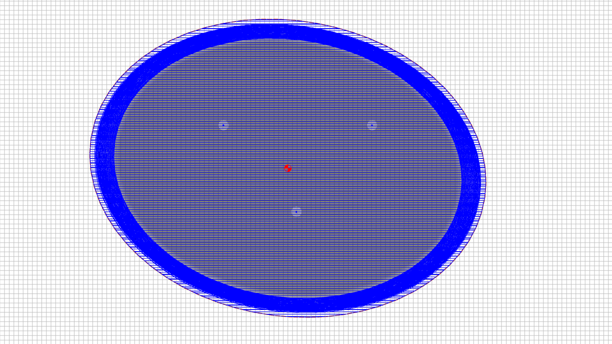
I don’t know exactly where the intersection of the STL & the top of stock is, so I make a boundary a little bit bigger, and get a toolpath like this. This allows a small discrepancy in actual stock thickness, if it doesn’t exactly match my design.
Restricting the toolpath creation to stay within the bounds of the stock material comes with unintentional consequences which may not be explicitly visible. This could cause some major frustration if a toolpath doesn’t give you the result you’re looking for - especially if you are using a complex cutting profile which isn’t directly supported & depicted in CC.
I would be in favor of a ‘bounding box’ solution though. By default, it could be set to the extents of the specified stock plus the retract height, but then for customized operations, you could adjust it beyond the stock bottom/top or limit it to a slice within.
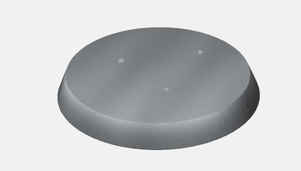
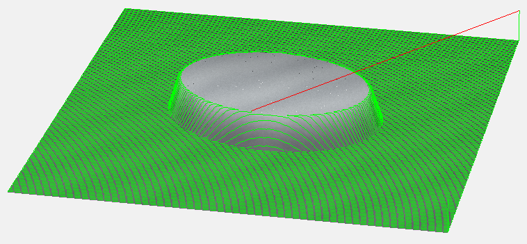
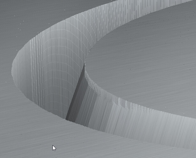
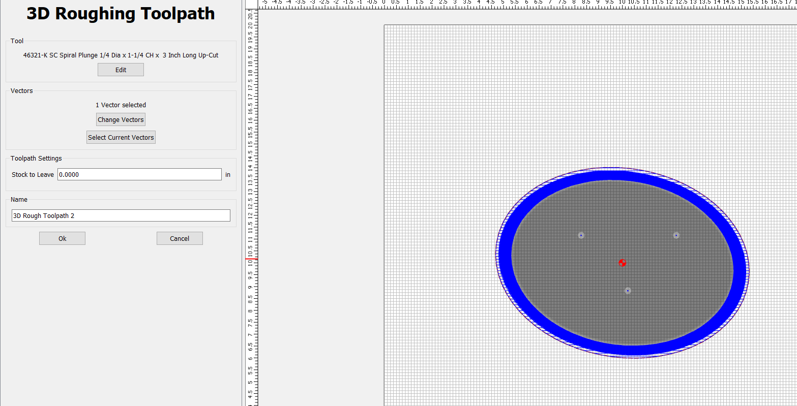
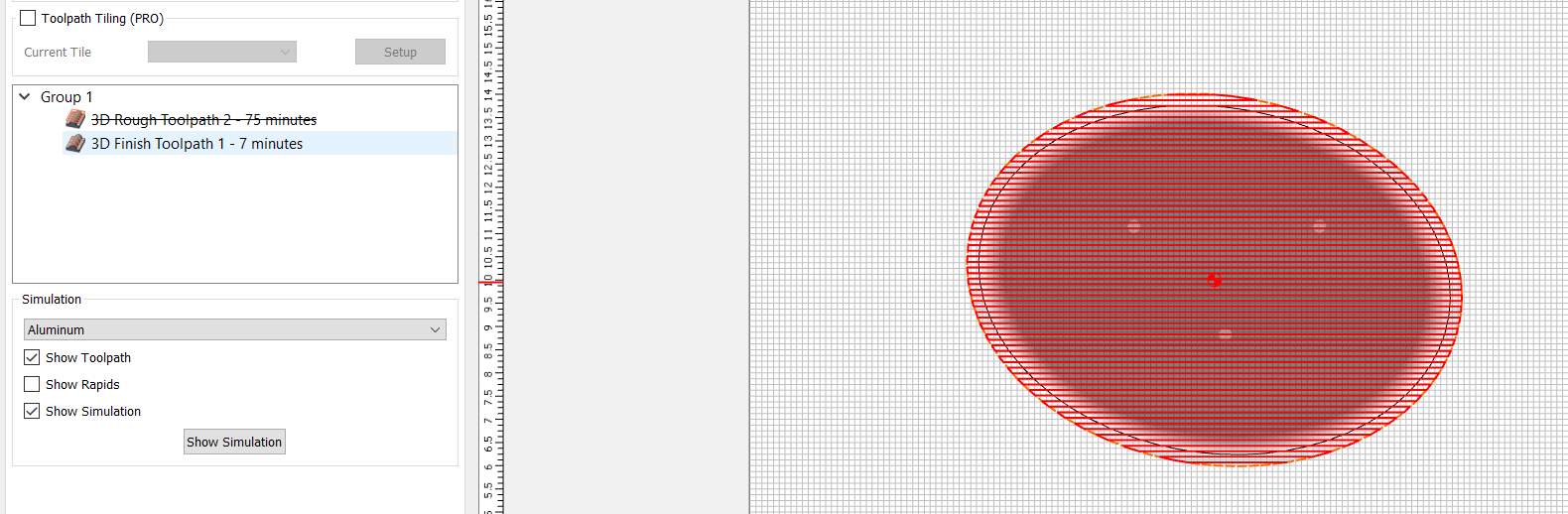
Selecting only the outmost geometry, the rough pass (with a .0005 remaining stock value), calculates around the outside of the object…note that nothing cuts the top of the object (except the ‘rapids’ to get to the holes). This makes sense, since the object is 1.5" and the stock is 1.5".
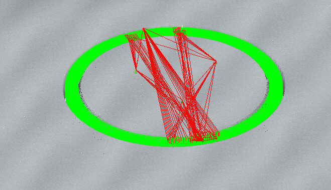
But…using the same geometry to set the finish pass, the calculation creates cutting passes across the top of the object:
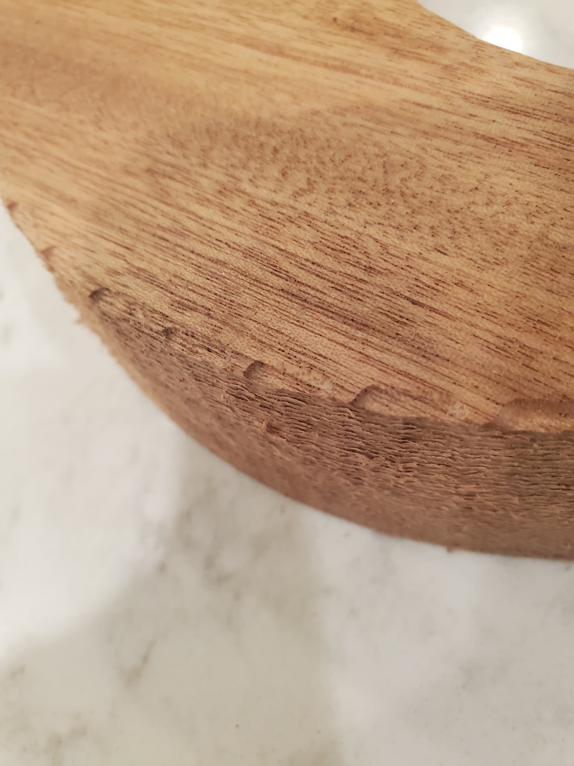
and ACTUALY CUTS GROVES INTO THE TOP OF THE OBJECT. Which makes no sense…It should not cut into the top at all (or MAYBE .0005" in…but it’s much larger than that).
The preview does not show the grooves…however, the actual cut piece does.
Why the finish pass calculations “see” the top of the board as a cutting target does not make sense - and is wrong…it should exclude the top, just like the rough pass does.
Again - not sure if this is the same problem that’s being discussed…but it is a problem I currently am facing.
Nope. Different issue. You only selected the outside oval, so the finish path is cutting everything inside that boundary. If you offset the outside boundary & select both, it will only cut between them.
The rough path doesn’t cut the top the part because there is no material to remove there.
But, since the object is 1.5" and the material is 1.5", there shouldn’t be any material to remove…I don’t care if it passes over the top of the piece, but it’s actually cutting
3D Finish toolpath cuts everything within the boundaries you specify. If you don’t want to cut the center, add another boundary curve. If you create a rectangle outside the workpiece, it will cut all the way out there too, even though there is no 3D model there.
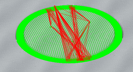
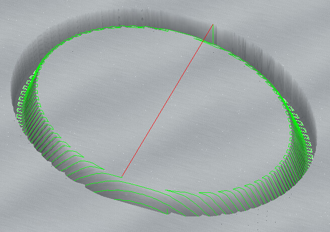
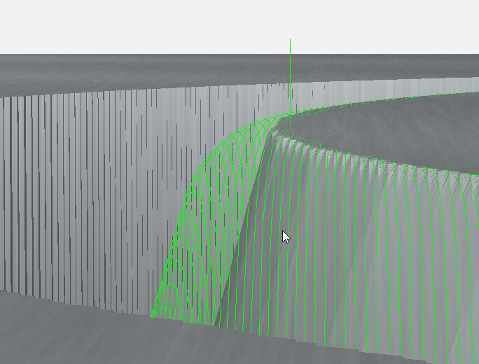
Well…yes… I tried that…the problem is, the gradient goes into the middle of the top of the piece (the white)…so where do you draw the inside geometry? I tried creating geometry on the inside of the grey gradient…and using the outer and inner geometry to restrict the paths. The finish path left this on the top of the piece:
as you can see, it’s cutting into the top right at the inside geometry. This does not show up on the preview…only on the cut piece. If I use only the outside geometry, it will cut lines across the entire top.
I can imagine that my Zero is potentially lower than the top of the piece…but it should only be cutting - at most - .0005 of material…these scallops are deeper than that
I notice in your project file that you’ve got the Z-zero from the top of the material with an 1/8" retract.
All things being equal, this would suggest that either the Z-zero point is somehow set below the top of the material, the Z-axis is losing steps along the way as it runs up/down during cutting, the bit is being pulled out of the collet during the run, or the material is warping up somehow as it’s being cut.
That’s just my 2-cents for what I would check to figure out what’s going on.
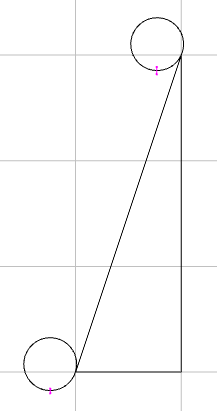
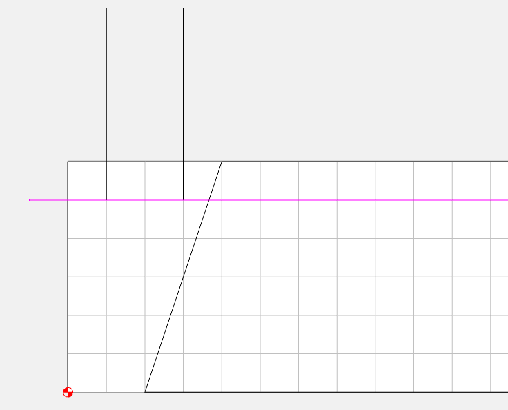
CC uses an “ON” condition for the boundaries, the center of the tool will be directly above the boundary with the ball tangent to the model. Ideally you want the offset that will produce that last tangent condition at the top of the cut without rolling over the edge.
This represents an offset of about 0.420. The problem is with the lace/zig-zag/raster cut, it works on the ends of the oval, but the sides still tend to wrap around a bit. reducing the offset to 0.375 prevents the sides from wrapping, but doesn’t fully reach the tangent point on the ends.
You could either model the shape taller to prevent the wraparound. (In which case we would not want the path trimmed off at the workpiece height.)
Or you could just use the rough path (Level based / 2.5D) to finish with a smaller DOC
Thanks Tod! I kind of figured it had to be something like this. Thank you for doing the ground work!
Unfortunately, the job is being done for an architectural firm that has supplied the STLs and is dictating the exact height of the layers (this represents one of 11 layers, each 1.5" tall). The height is the key dimension. I don’t have the luxury of altering the height of the components.
I actually had already arrived at a “solution” - which was to avoid the finishing pass altogether and just make the rough pass within thousandths of the real value. Since the “modeling” is just a slanted edge, the rough pass is “good enough”. I will sand for smoothness after I assemble the layers. The rough pass does not have the issue at all. I actually haven’t tried leaving “0” inches on the rough pass…but that might not be a bad idea…and see what happens…but .0002 has been working fine.
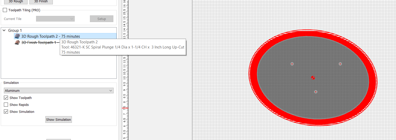
@robgrz Do you have any thoughts on Tod’s analysis? Is this something CC can adapt to manage? It seems to me that it ought to know that the top does not need to be touched on a path that’s at the height of the workpiece - and could optimize (for speed) the way the rough pass does:
For example, this is a rough pass with 0.0000" left behind
Note the optimizer avoids passing over the top of the piece (because it knows the height of the piece is already 1.5" and the model calls for 1.5" on top.
However - the finishing pass, set to the same geometry/vector optimizes as:
Thanks for those thoughts, Joel. I did consider some of that already and had made sure the stock was dimensioned perfectly flat and that the bit was solidly mounted. It IS possible that the zero of the bit was actually slightly below the piece (I use the paper method to zero), but I still would think that the problem would show up on the roughing pass with such a small remaining amount set.
I think Tod has found that the root problem is actually the way the calculations are set in CC relative to the bit geometry. I can get away with a little cheat, as I said in the last post, because of the nature of this particular project — but it might cause me trouble in another project.
Rough (Z-Level) and Finish (Lace/Zig-zag/Raster) are 2 different types of toolpaths.
Rough 3D is level-based. It drops down from the top of stock by the DOC and creates a plane. It sections the part through that plane, then uses the resulting section to do a pocket. Then it drops down another DOC & repeats the process. The cutter starts at DOC below the top of stock, so there is no opportunity for it to cut across the top.
Whereas the finish toolpath does a lace/zig-zag pattern & adjusts the Z to keep the tool in contact with the 3D model. If there is no model, it cuts at bottom of stock. If you don’t limit the bounds with curves, it cuts over everything.
They are both, for the most part, working as designed.
If I’m cutting a shape that imports just a bit higher than the nominal stock height, I don’t think I would want the software clipping the toolpath and cutting those areas flat, or retracting & reengaging. I would rather it just cut the shape I gave it.
If I make a mistake & import the shape 4" taller than it needs to be… Mea Culpa!! I should have previewed the 3D shape before applying the toolpaths.