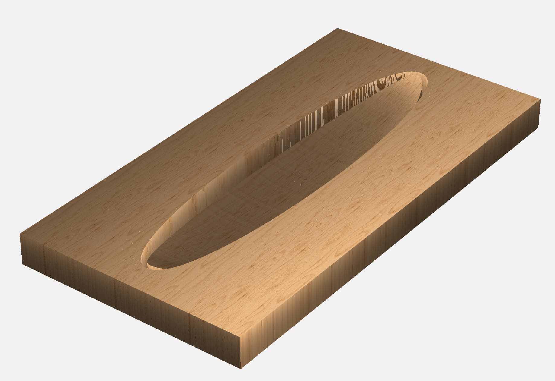
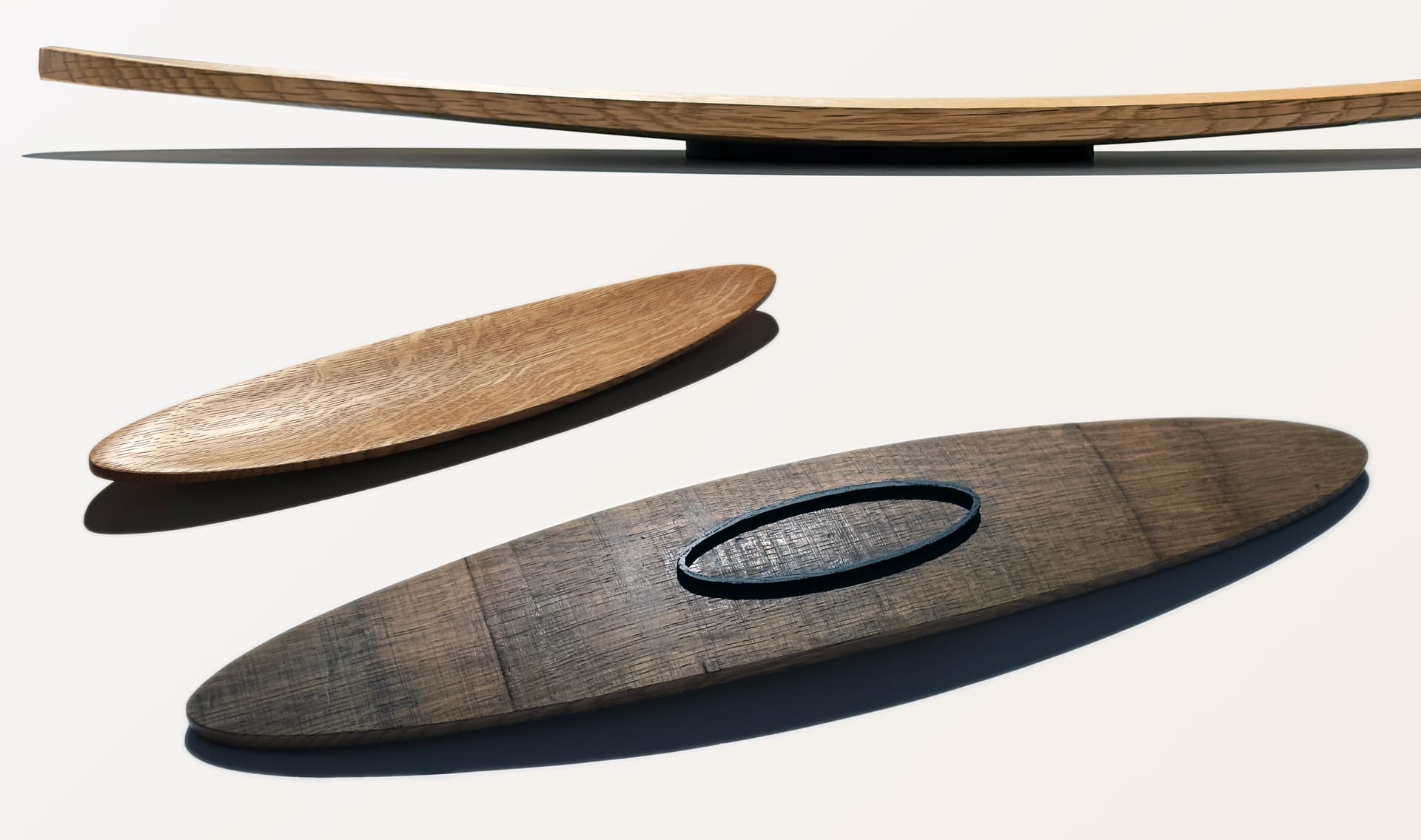
I am making a shallow, wide bowl out of a single stave of a used whiskey barrel. I have modeled the carve I need to make to reveal the white oak buried under ~.25" of sweet-smelling charcoal using Carbide Create Pro. However, in order to make this shape, I have to fool the software by making the stock much wider than it actually is, meaning that I will end up cutting air most of the time. Is there a way to clip the cut area without changing the compound curve? In my experiments, when I do this, it forces the Z height to be wrong at the edges in one axis, even if the center bottom of the bowl is correct. In simplest terms, imagine you wanted to slice a wooden bowl such that you were left with a single thin arc through the middle. And you started with a piece of stock that was already that shape, just thicker.
Hi Walter…if you highlight only the area you want to cut when establishing the roughing and finishing toolpaths, it doesn’t work? I had that problem before and Will corrected me in my selection strategy. I can’t tell if that will help you or not…
[EDIT] This comment is what I mean:
- Gary
Draw a rectangle around the area you want cut. Select that rectangle as the boundary for your 3D cuts.
The shape doesn’t let me do that. The shape of the stock as well as the shape of the desired finished piece is a compound curve, with two different radii. The piece of wood is 2’ by 5", and on the long axis, it has a radius of maybe 5’, while on the short axis, it’s a slice of a 2.5’ circle, so 1.25’ radius. If I make the shape 24x5 inches, with a centered oval depression in the middle, I have a rim that is all the same height. But the shape I need is curved on the z axis all along the rim. I truly need to slice out a portion of a much larger shape, but I don’t want to waste all that time cutting nothing.
Use the larger vector(s) to create the 3D model. Use the smaller vector to cut it.
Post the file?
We’ll gladly walk through this w/ you.
If you add a new vector that encapsulates the outer bounds of the desired finished product, and select that vector for your rough and finish passes, you’ll only cut air on the parts of the design that are between the finished product and bounding vector. The closer you make it, the less air you’ll cut.
I think the penny has dropped. I was trying to describe my problem, but it was actually only a problem with the modeling tab, not the toolpath tab. I had conflated the two. I already had a path for the final outline cut, and once I chose that as the base for my tool paths, I got the best of both worlds. The shape (and the virtual stock size) have to be larger in order for the modeling to work out, but the cutting is separate from that. I’ll try to remember that.
Sometimes it takes several people explaining the same thing with different words.
Glad to hear it “Clicked” ![]()
Looks kinda like a butt plate for a rifle.
More advice to try
Draw your center bowl area just like you did
Draw a flat shape and then Use the equal function component build from the edge of the box all the way over to your center circle. The equal function will blow away anything in its path.
You may have to play with it a bit, but you can build your shape this way
And someone stated you could always just cut your roughing and fine, pass inside the oval and leave everything else alone. At least no air cutting involved this way.
A 10% overlap on cutting bit will reduce the chatter on the side cut.
Just another way of doing things
Be safe
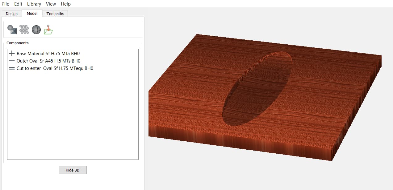
walter davis oval.c2d (1.2 MB)
Use Disable tool to see each component Build
each component build Name is written so you can read how the build was made.
Make some saw dust. Eye wear be safe.
Thanks! I will give this a look tomorrow!
Thanks! That’s really cool, I didn’t figure out what the equals path was for in all my experimentation. It seems to provide the same final shape as @Tod1d 's solution, which is also interesting to me. ‘Many paths’, and all that.
Walter
More sauce for your goose.
The difference in the two options. Todd’s option is the simplest. Works great and quick.
If you want to build more components in your model, it’s good to learn now the equal function works.
Small line you see on your project maybe scalloping. Here’s a good article below.
Author is some guy name, Robert Grzesek. I’m sure he’s familiar to a few people. He is the CEO of Carbide 3-D.
It’s a repost from this form topic. By Dan Nelson.
Hope I got all that right I’m sure someone will correct it if it’s wrong.
Be safe
This topic was automatically closed after 30 days. New replies are no longer allowed.