WillAdams
August 13, 2019, 11:07pm
101
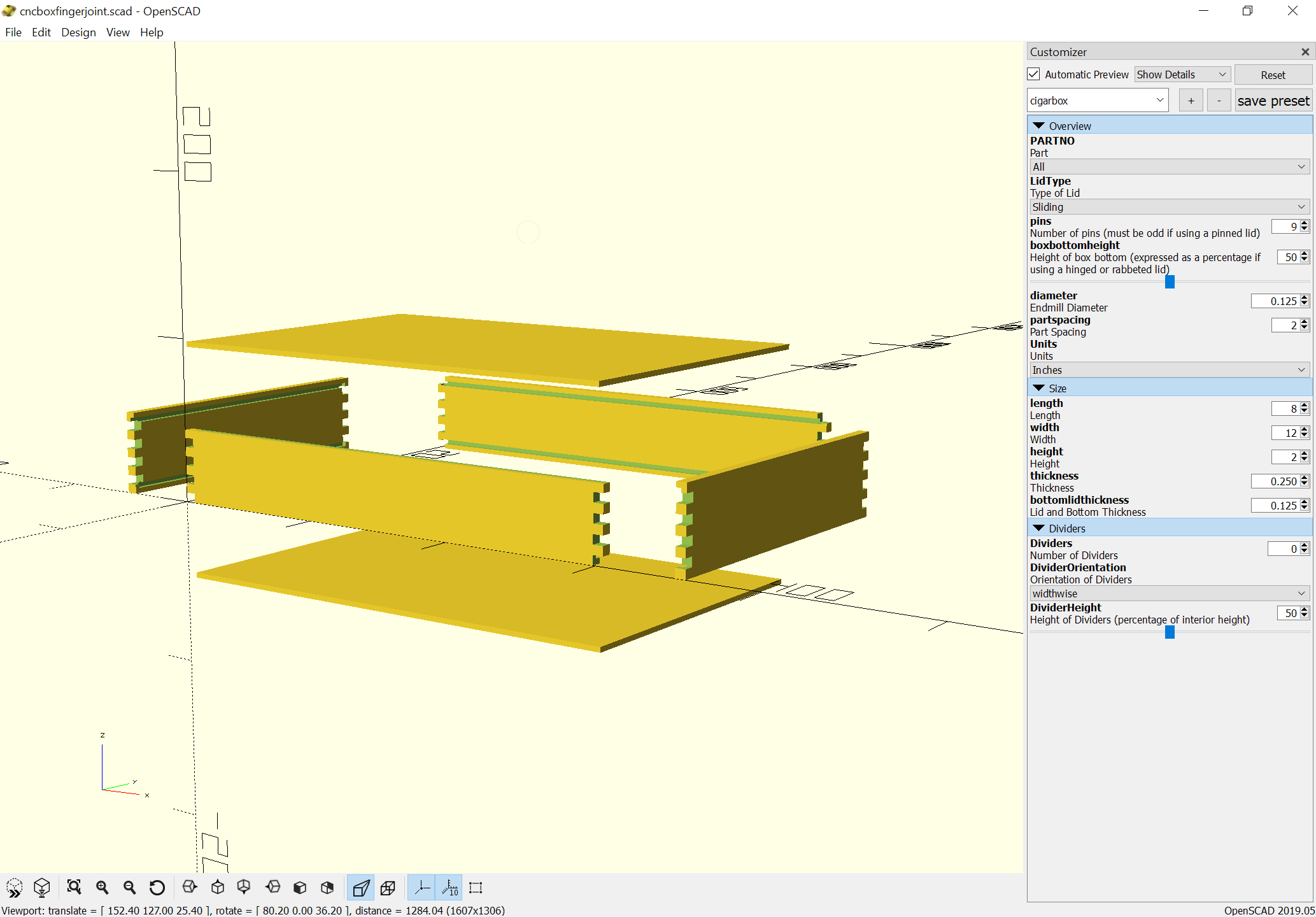
Working up a design:
which makes this:
cncboxfingerjoint-cigarbox.pdf (8.7 KB)
which can then be opened in Inkscape and resaved as an SVG:
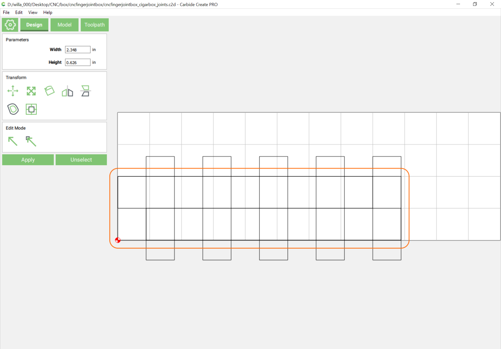
Which can then be opened in Carbide Create. Use the two boxes which have three boxes to cut the sides and front and back — the top and bottom can be cut directly from the geometry for them. It will be necessary to draw in the geometry for the dividers.
Then use the structures at the top left to cut the fingerjoints using the fixture at: https://cutrocket.com/p/5cb25f3380844/
1 Like
WillAdams
August 13, 2019, 11:48pm
102
That .svg will need to be sized down to 75% of the size
WillAdams
August 14, 2019, 12:18am
103
The sides will need to have mirrored slots for the sliding lid added:
cncfingerjointbox_cigarbox_sides_front-back.c2d (43.5 KB)
WillAdams
August 14, 2019, 12:23am
104
For the joints, if you wish, you can cut the boards a bit long and then when you mount them use this geometry:
to machine them flat/even before cutting the joints (I would recommend doing so).
cncfingerjointbox_cigarbox_joints.c2d (50.7 KB)
1 Like
WillAdams
August 14, 2019, 12:01pm
105
Here is the source file which has the lid and bottom in it:
cncfingerjointbox_cigarbox.c2d (55.1 KB)
WillAdams
July 29, 2020, 12:29am
106
Worked up a generalized fingerjoint box with fingers all around:
https://www.blockscad3d.com/community/projects/966268
1 Like
WillAdams
August 1, 2020, 12:55pm
107
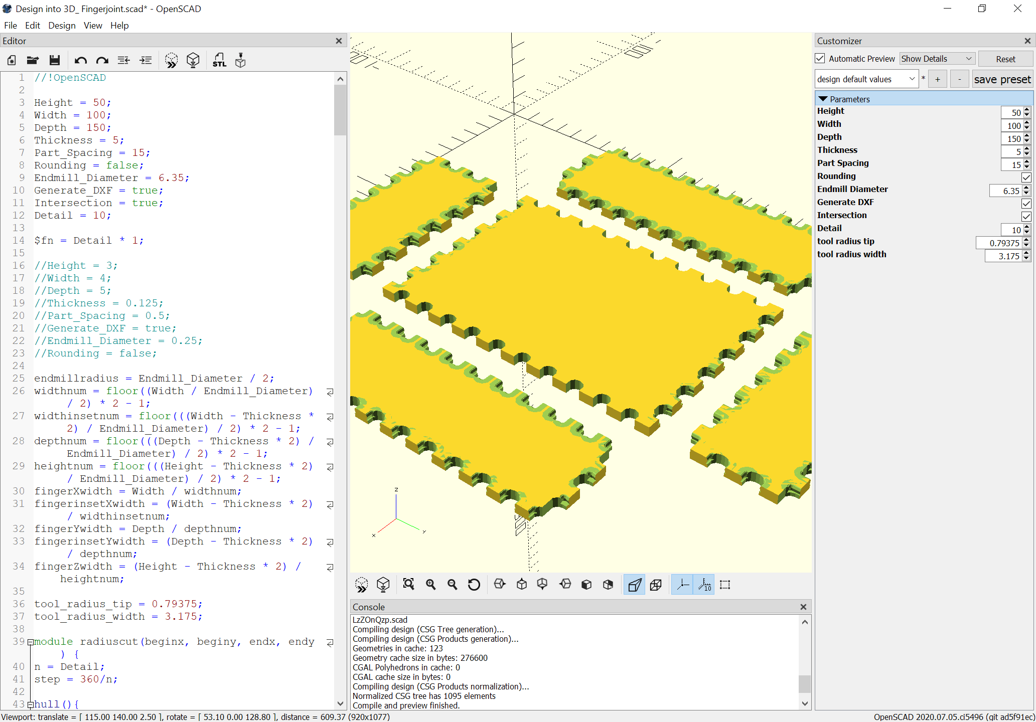
Reworking this a bit, I now have a version in OpenSCAD which previews without thin not quite removed parts when modeled with rounding:
WillAdams
August 1, 2020, 3:16pm
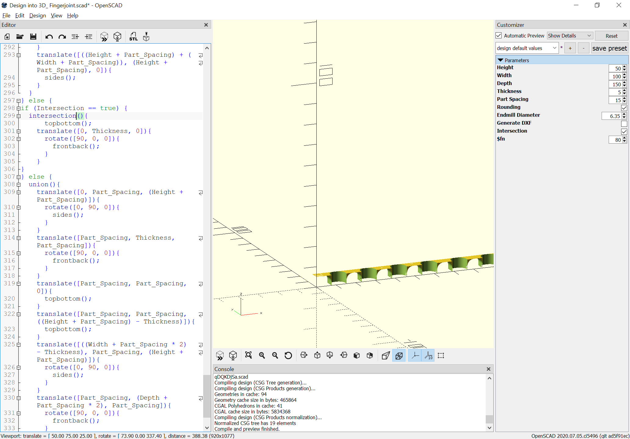
108
Putting two parts together and showing their intersection shows the material which needs to be removed:
WillAdams
August 1, 2020, 7:14pm
109
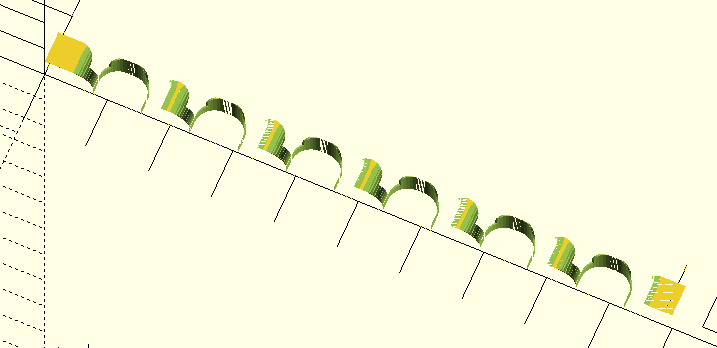
A glitch. hull doesn’t work properly with concave geometry:
Will need to define a module in such a way that that isn’t an issue.
WillAdams
August 1, 2020, 8:30pm
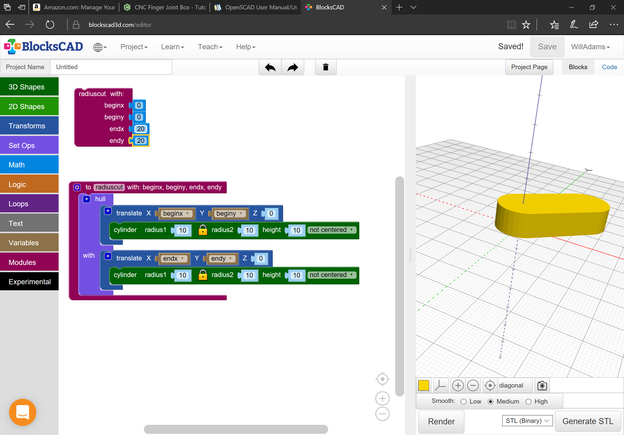
110
One option here is to do pairs of cylinders at the begin/end points which are joined via a hull operation:
it just needs to be joined up with a loop which stacks them in increasing sizes so as to create the radius endmill shape.
WillAdams
August 1, 2020, 8:40pm
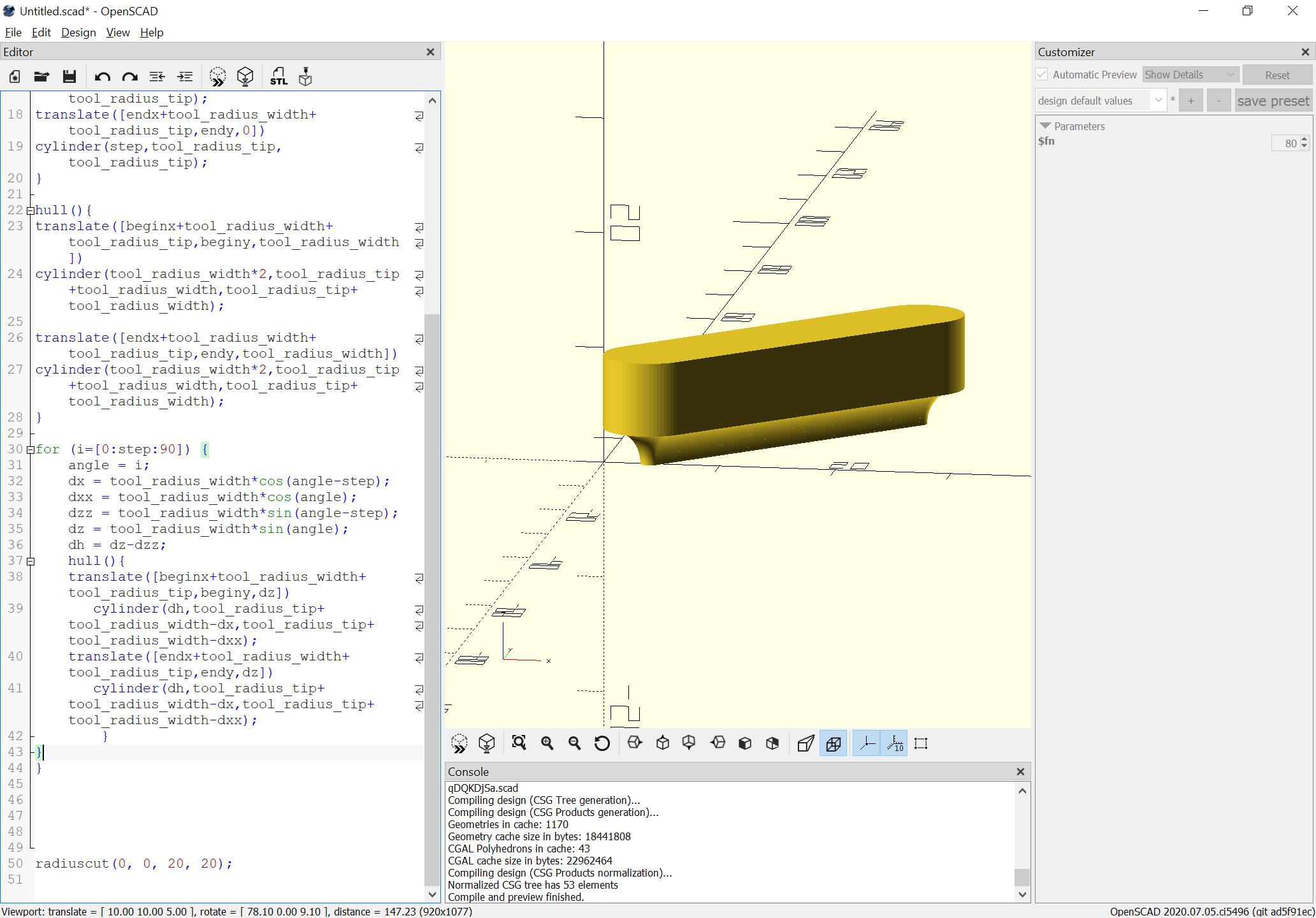
111
Which once made produces a representation of the cut:
WillAdams
August 1, 2020, 9:09pm
112
Which works when one is placed manually:
next up is seeing what’s involved in adding them to the appropriate module or in some other programmatic fashion.
WillAdams
August 2, 2020, 12:12am
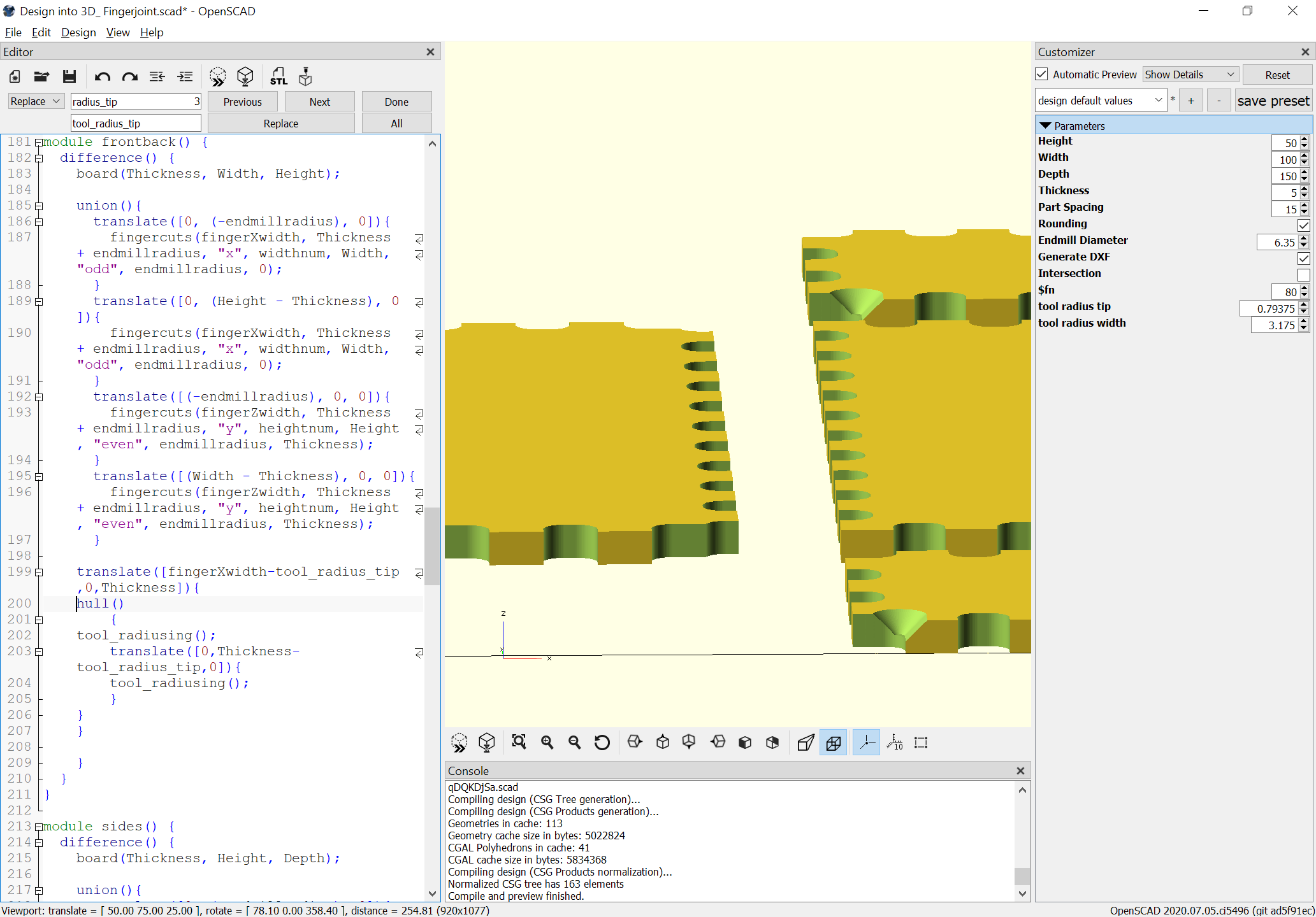
113
Adding a few loops we arrive at:
which shows a good fit:
Will are you adding tolerances to these cuts?
WillAdams
August 2, 2020, 1:15pm
115
Not yet. I need to work out how I’ll get CAM done before I introduce that.
I just have one more pair of edges to finish the rounding on:
unfortunately, this bogs my machine down when I turn on rounding, so will have to look into that.
File: Design into 3D_ Fingerjoint.zip (2.1 KB)
In Vcarve I use an “allowance” feature to make things fit, but it has been easy to determine whether the cut is an “inny” or an “outty”. I’m not sure how it would work with these box joints.
1 Like
WillAdams
August 2, 2020, 3:08pm
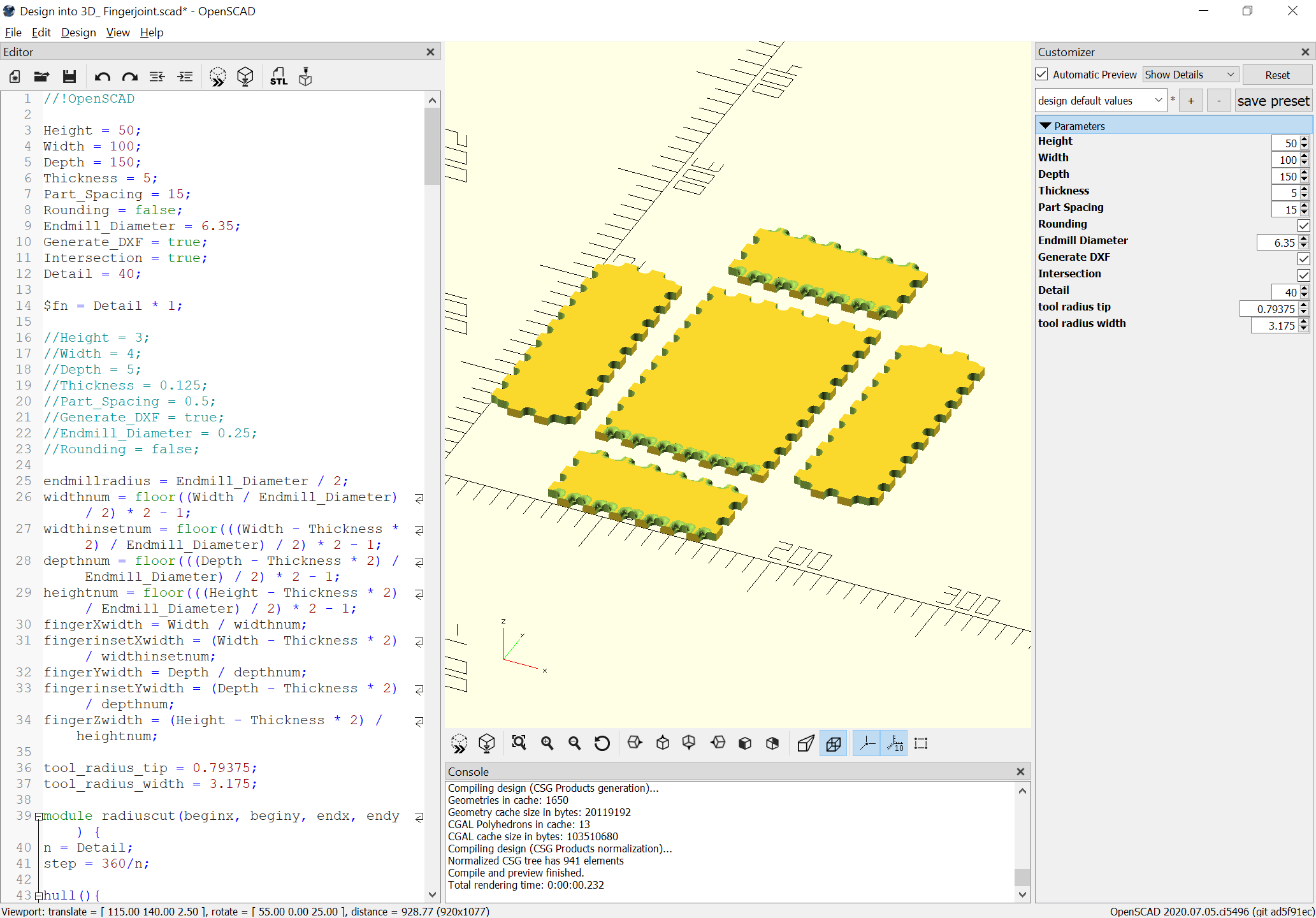
117
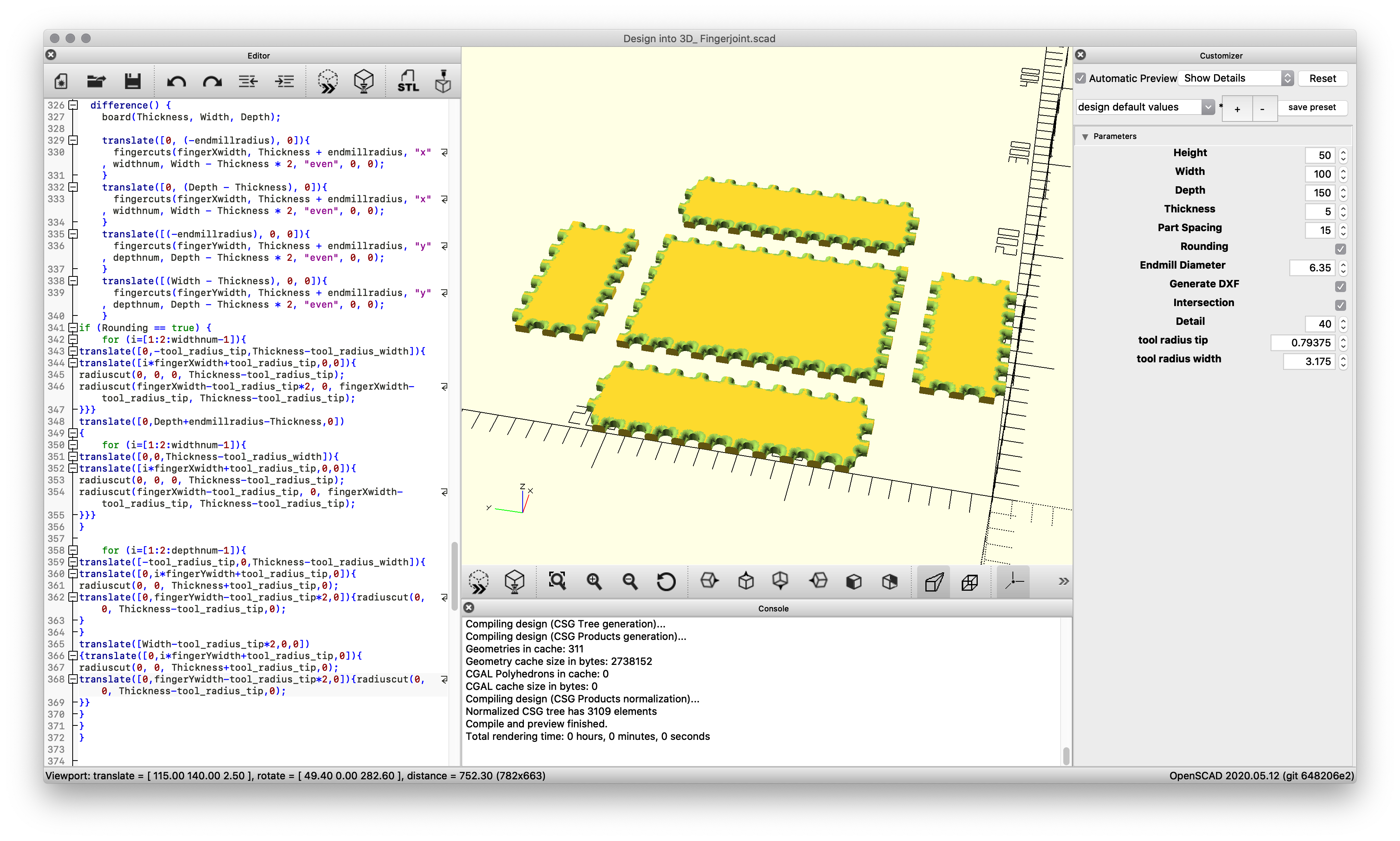
Okay, fixed a problem, and added the rounding along the sides of the top/bottom:
Unfortunately, performance isn’t much better on my MacBook, so sort of stuck.
The tool movement which would be needed is simply a series of lines, but OpenSCAD won’t draw those so that they can be exported to a DXF. It wouldn’t be so bad if there was just a way to write numbers out to a file (other than the JSON used for customization).
WillAdams
August 2, 2020, 3:12pm
118
File seems fine from a 3D modeling perspective:
Design into 3D_ Fingerjoint.scad.zip (2.5 KB)
See further discussion on /r/rapcad and /r/openscad on Reddit (the OpenSCAD forums are down at the moment)
WillAdams
August 4, 2020, 3:31am
119
Unfortunately, there isn’t a way to use OpenSCAD to create a DXF ready for cutting with a radiused endmill such as:
https://www.amazon.com/gp/product/B00Q8M1SRS
Fortunately, just a straight line move is needed, so it ought to be workable to just define it as a square endmill, have it plunge and then make the cut and lift out.
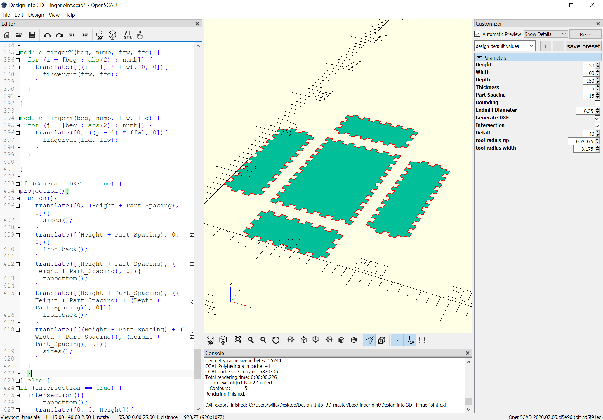
We start by exporting the flat design:
(hopefully the radius of the endmill will reasonably match the radius of the cut)
then import the DXF:
Design into 3D_ Fingerjoint.dxf (29.7 KB)
Assign thickness to match the material (5mm), then a profile cut, then we have to define the radiusing tool.
WillAdams
August 4, 2020, 3:44am
120
Drawing up the tool reveals a tip diameter of 1.5875mm:
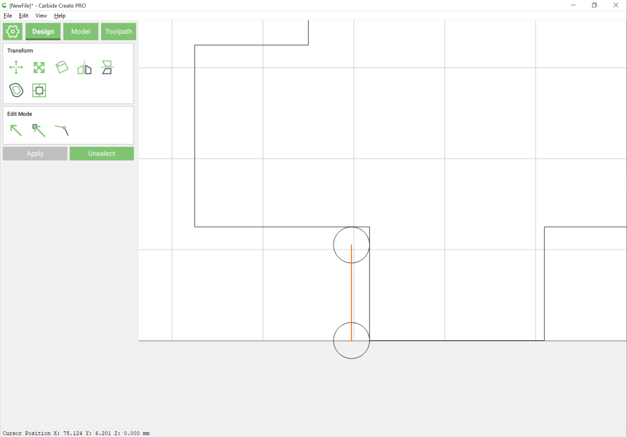
Defining a tool of that diameter we then have to work out the placement of the toolpath — working with a pair of circles of that diameter and drawing from center–center we arrive at:
where the open (magenta) line should be the cut we want made at a depth of the radius we want cut.