by just moving the tool in a suitably sized circle at the depth to cut a hemisphere of the size which the radius tool could cut.
Instead, we will make a series of cuts using a square endmill from a suitably sized piece of stock — two series:
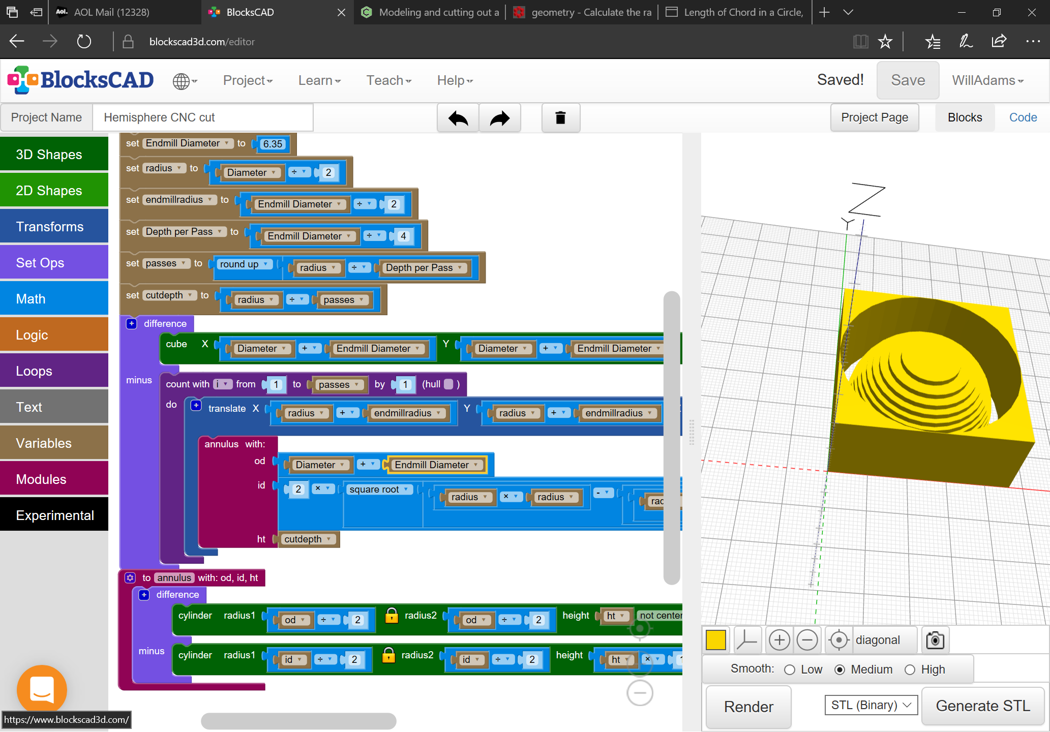
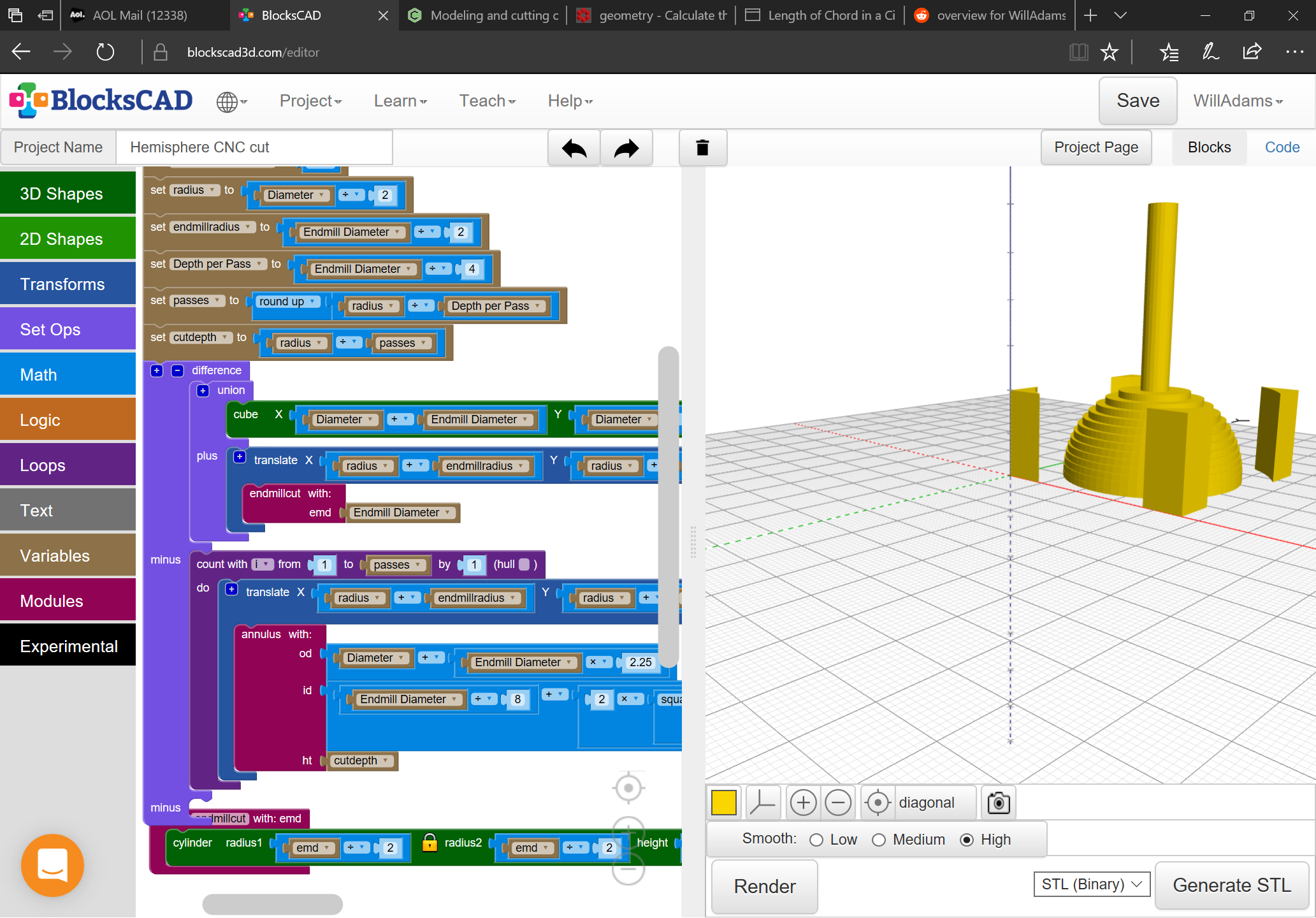
first a series of rings with an increasing central diameter at ever greater depths so as to describe the hemisphere as if it were a Ziggurat, cutting out the latitudes of the shape
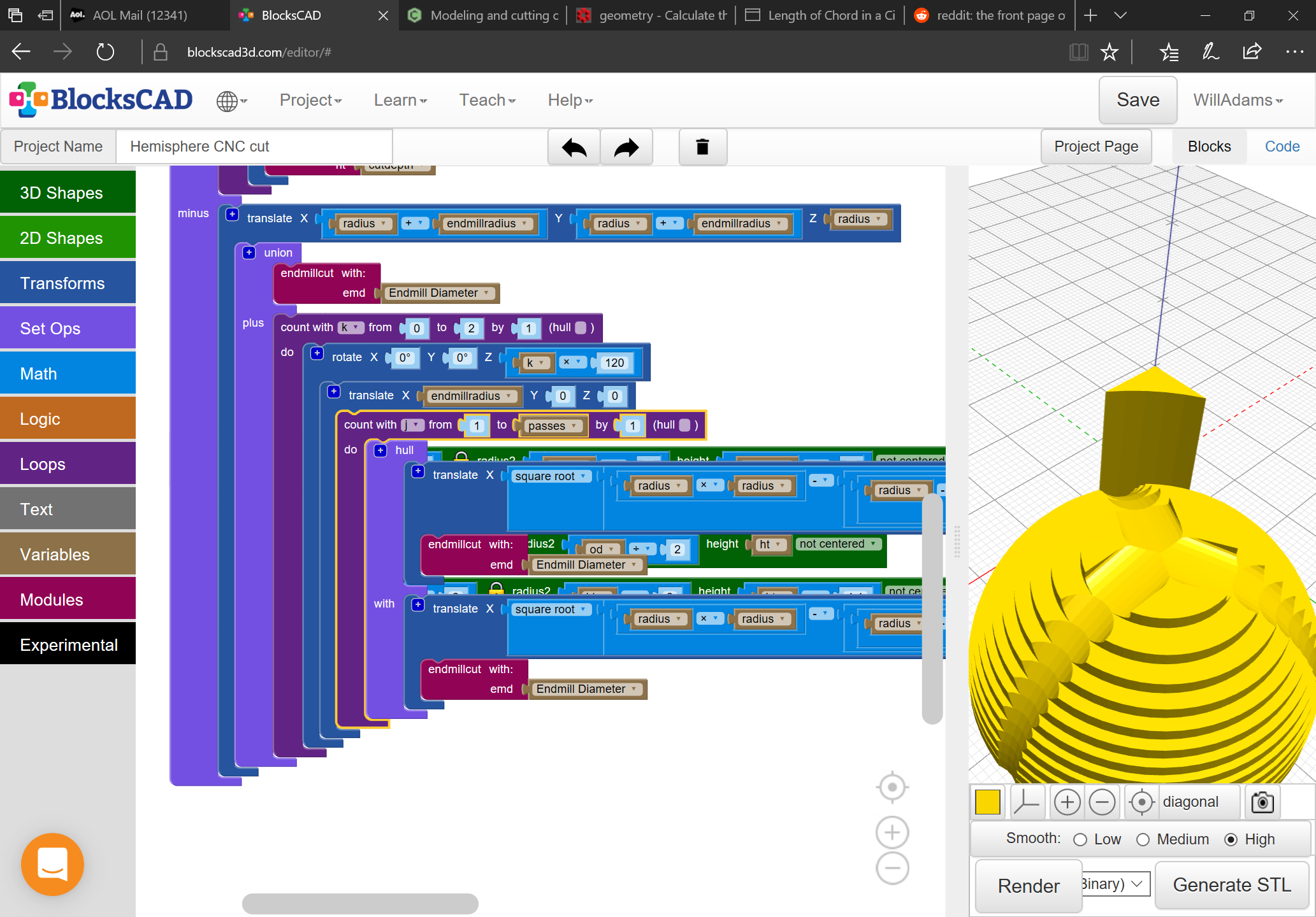
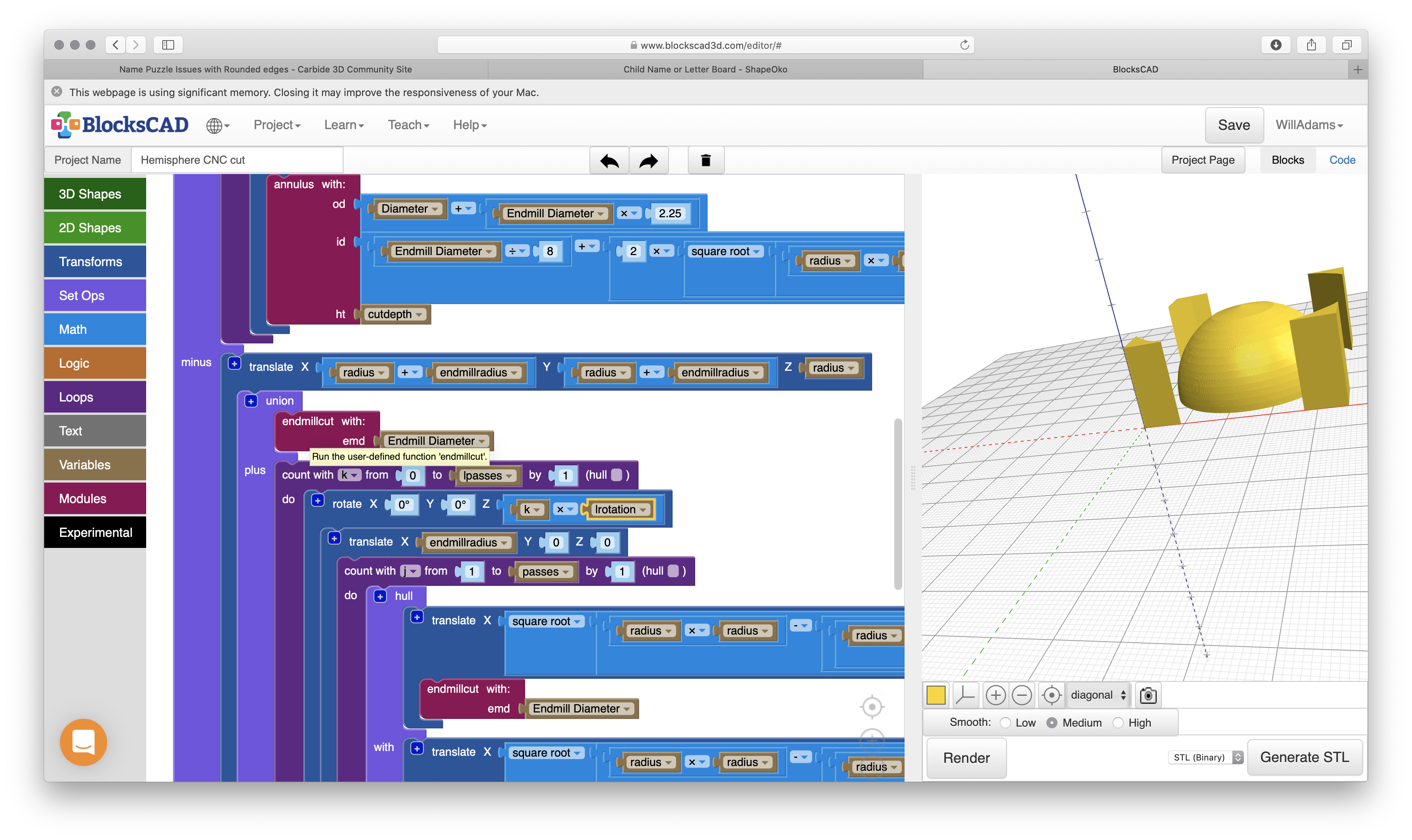
a series of hemispherical moves over the longitudinal axes of the hemisphere — note that at the apex the movement will need to include additional movement for the diameter of the endmill so as to clear the top of the hemisphere
As with other projects, we’ll start in Blockscad modeling first the stock and some basic variables, then define modules for the two sorts of cuts, and a pair of loops to then cut out the shape.
next we need to make a module to cut out the diameter of the hemisphere through to an inner circle (leaving a roughing clearance) and work up the math of calculating the diameters for each cutdepth.
Next is modeling the longitudinal cuts — doing this emphasizes why CAM tools usually use ball-nosed endmills for generalized 3D movement, since for this basic version we need to continually transition from:
no offset for the initial position at the top center of the hemisphere
offset by radius for the movement down
which I suspect is may result in a circular artifact at the top — we’ll see what a test cut reveals