The Nightmare Is Over!!! 
I have solved the problem and wanted to share the information with the forum. Hopefully this information helps others. The issue seems to be with the number of decimal places used for accuracy and the handling of mm to inches conversion. My fusion 360 drawing was done using mm as the units of scale. When I ran the CAM, I selected inches as my units since all of the end mills sold by C3D are in inches and since most of the specs on the machine are listed in inches. ( work area listed as 8" x 8" x 3" and speeds are listed in inches per minute.) Even though my CAM file units were in inches, and my end mils were in inches, I kept wondering why Carbide Motion kept displaying the X, Y, and Z in mm while homing and marking the work zero location. @rogwabbit Roger’s response about GRBL documentation got me read the GRBL standards to see if I could come up with anything. Ultimately, I decided it must be a rounding error on the conversion from mm to inches. I went back to Fusion 360 CAM and made the units conversion to mm and then edited all of the fields to display only 3 decimal places (rounding up or down as necessary) since GBRL is only accurate down to 0.001mm. I did the post process and ran the updated file and Bingo, it worked. I could have saved myself some time and real headaches if this was better documented. I have since found that this issue has been around more than a year as evidence in the below thread. Wish I had read the whole thing earlier, but I’m glad I figured it out.
Here is what my project looks like after milling. I have come clean up work to do on it, but I’m very impressed with the level of detail.
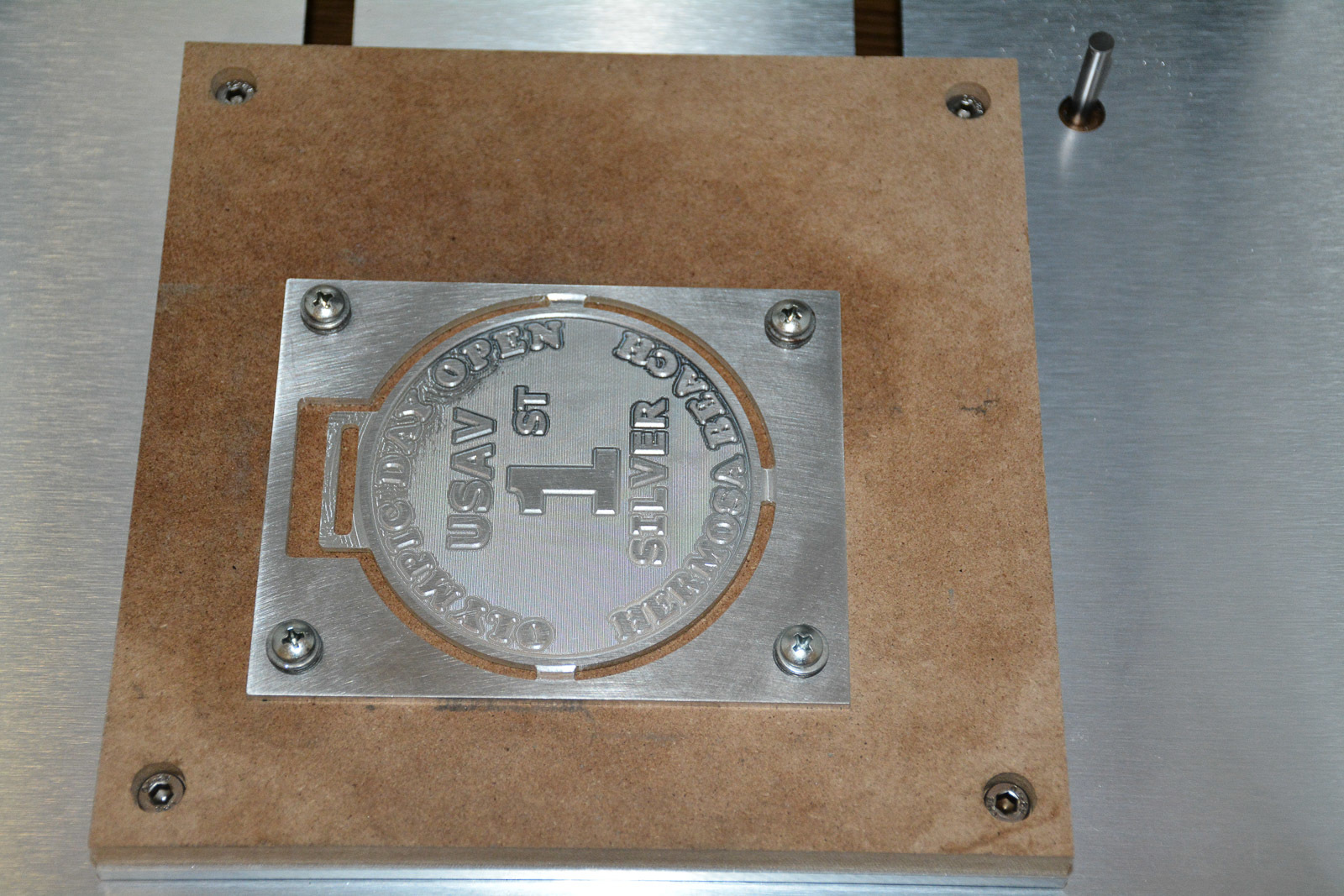
This took job took 12 hours to complete and was done with a 1/16" Flat end mill and a 1/32" flat end mill. I plan on cutting this in brass plate next and will share more details when I do.
Cheers
Allen