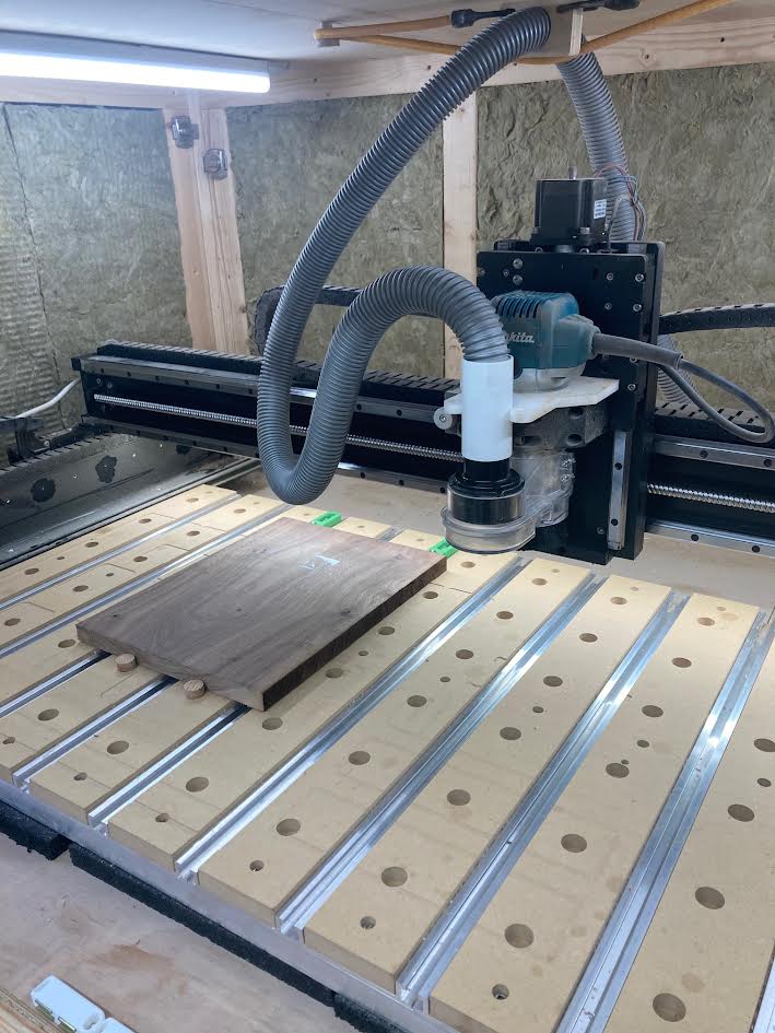
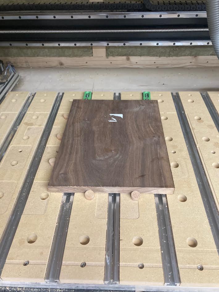
I’ve watched a few youtube videos about dog holes and decided to give them a go on my SO5. I’m hoping they will help me with aligning workpieces, enable repeatable positioning (e.g. for two-sided machining, batch production etc.) and give additional clamping options. It’s very early days and I would be keen to learn from anyone else who has done similar.
I’ve also configured the user-macros in Carbide Motion to create work zero points based upon the dog grid. This should mean I can slot in a piece of wood and then choose the corresponding zero point as a pre-set value. No probing needed!
Lessons learned so far are as follows:
Dowel sizing for the inserts really matters. I created some oak cylinders that are 19.80 mm but in a 20.00mm hole, they have a lot of play, giving inaccurate workpiece positioning. Will need to make some new ones that are more like 19.95mm.
I could only go 15mm deep into the wasteboard so I don’t cut the machine itself - most dogs you can buy online will be considerably deeper than this, limiting your options.
I wanted a 100mm x 100mm grid, but as the wasteboard slats are 4 inches apart, I had to use 101.6mm for the x direction, which is kinda annoying to my metric mind. As it turns out, the slats are ever so slightly more than 4 inches apart, so even at 101.6mm, the dog holes are off-centre towards the right of the machine, as you can see in the picture.
Any other wise tips or tricks from the C3D community?
The last time I did holes for inserts, I had resolved to have a master file and cut the holes and install inserts as-needed, where needed, updating the file as each hole was added.
I think you’re right there - I can see the ones at the front left of the machine getting a lot of use. I’m not sure if they will lose tolerance over time as the holes get warped or damaged from regular use. Only time will tell, but I may have to reserve some of the holes for occasional high-precision work.
That did not last long — it was a small panel in my then Standard-size SO3 which was obsoleted and gifted to a school when I upgraded to the XL size, after which I did T-tracks which slightly varied spacing which worked out well (and which every so often, I wish for of the Hybrid T-tracks).
I did the holes just along the left and bottom. I put them too close to the bottom for the clamps to work properly so I have to add support on in front of the machine.
Many times the left side positions work such that I can’t get a clamp from the T Track to secure the right side so I have some spacers I can use on the left to shift things slightly.
Also, for “dogs” I just used cut off pieces of PVC. Easy to get in and out. They are easily replaceable and if they are too tall for a particular project I can just cut them down.
While typing this an idea occurred to me to address the problem of not being close enough to the T Tracks for clamps on the right. I can machine another slat with holes all the way through but off center so that the right side of the holes is X inches from one side and the left side of the holes is X + Y inches from the other side. Then put it over the PVC with side A facing right and machine the edge to make sure it’s parallel to the Y axis. Then flip the board over or end for end and machine side B.
That all makes sense in my head but not sure if I described it well.
In the top of that board I will sink threaded inserts for the clamps to attach to on the left side of the material. With the variability of Side A and Side B I should be able to get the right of the material close enough for the clamps to engage.
Too bad I am literally 1 hour into a 2 week trip away from my machine. I will definitely give this a go when I get back.