Team Nomad is on fire !
It’s interesting to see such diverse entries, yet another testimony to the versatility of our machines.
(and welcome @Olle! no better way to make a first post)
5 Likes
Thanks for the welcoming guys! I’d love to see that part if you end up machining something similar @PhilG!
1 Like
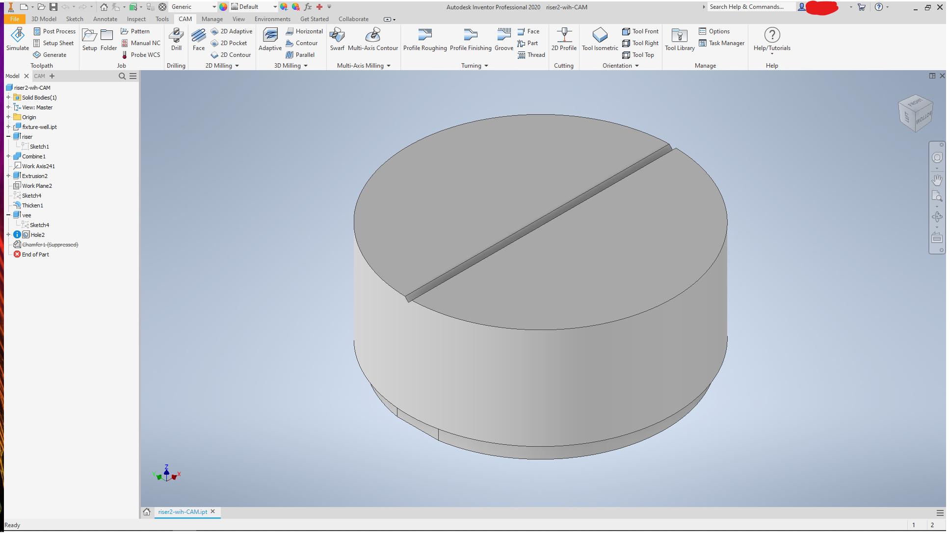
Why not throw another one in, since at the moment I don’t think I’ll have the time to do something artsy. Another part for a comparator. This time a riser with a fine vee-groove for inspecting and measuring small round things (tools for the Nomad, among other things, but actually made so I can inspect pars I am working on for actual work)
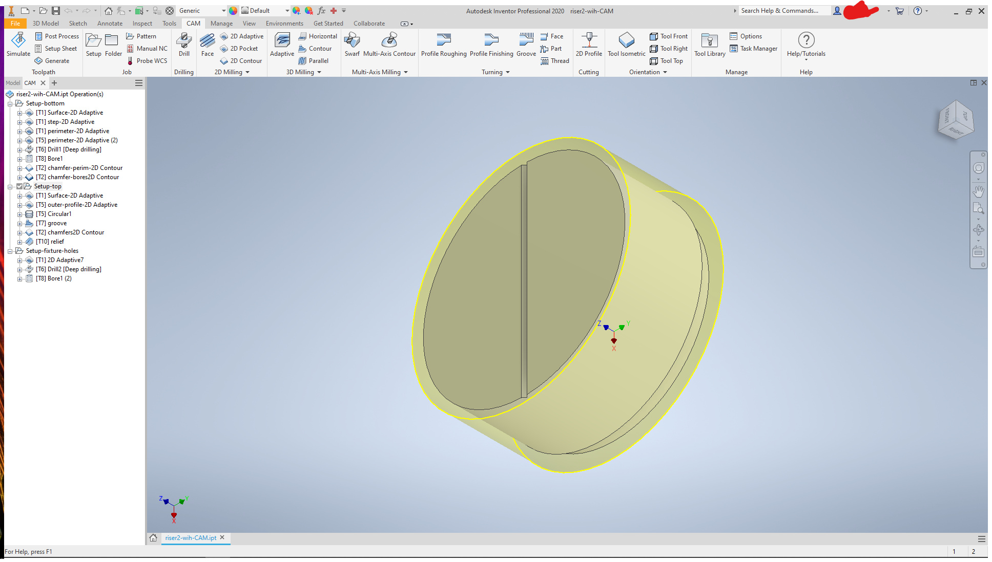
This is based on the same base model I posted the other week. All I changed in the model was the height (parameter value) and the groove profile.
The model:
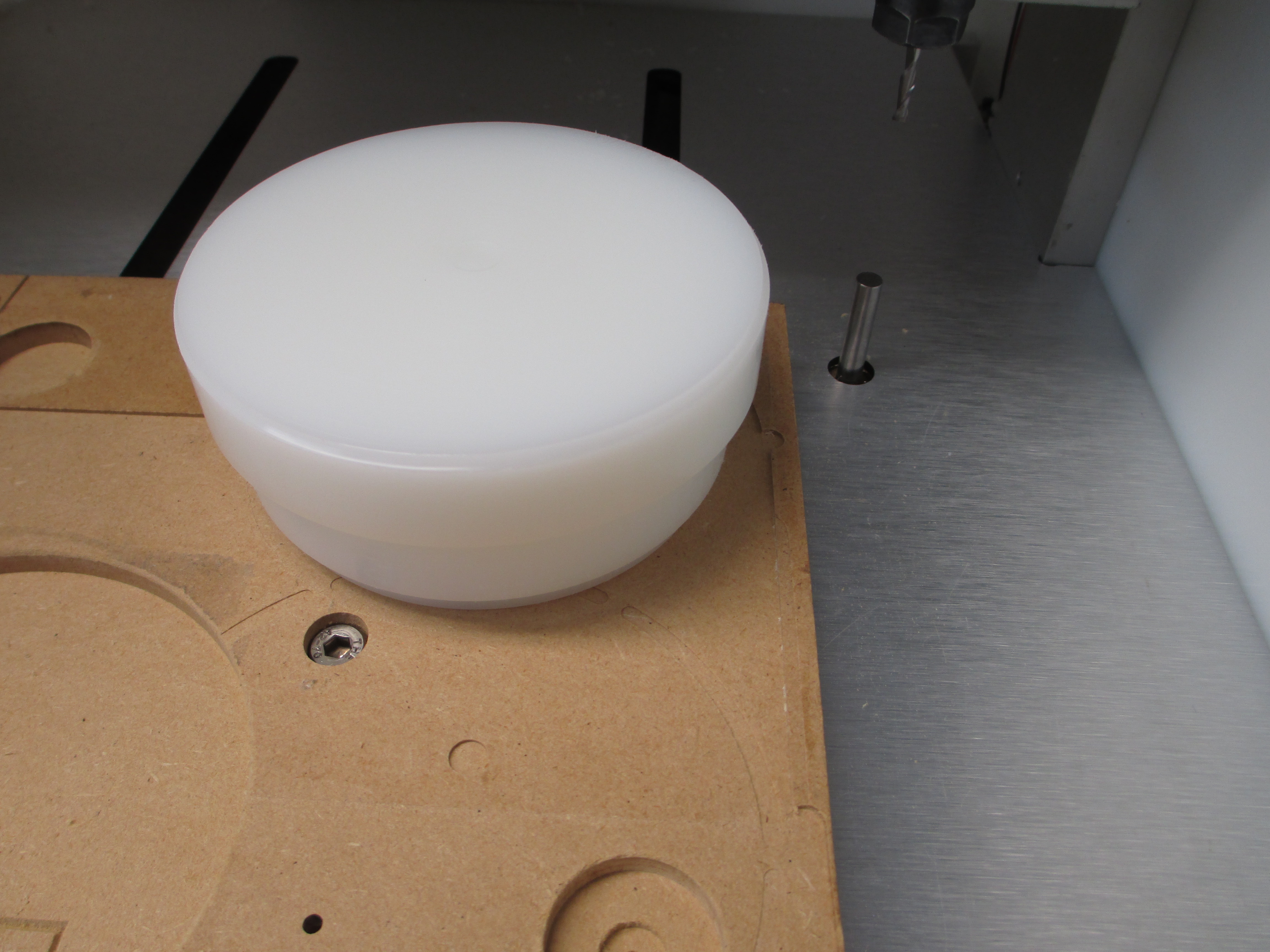
This was machined in two setups. The first was from raw stock. Here, the stock was pocketed into the wasteboard,
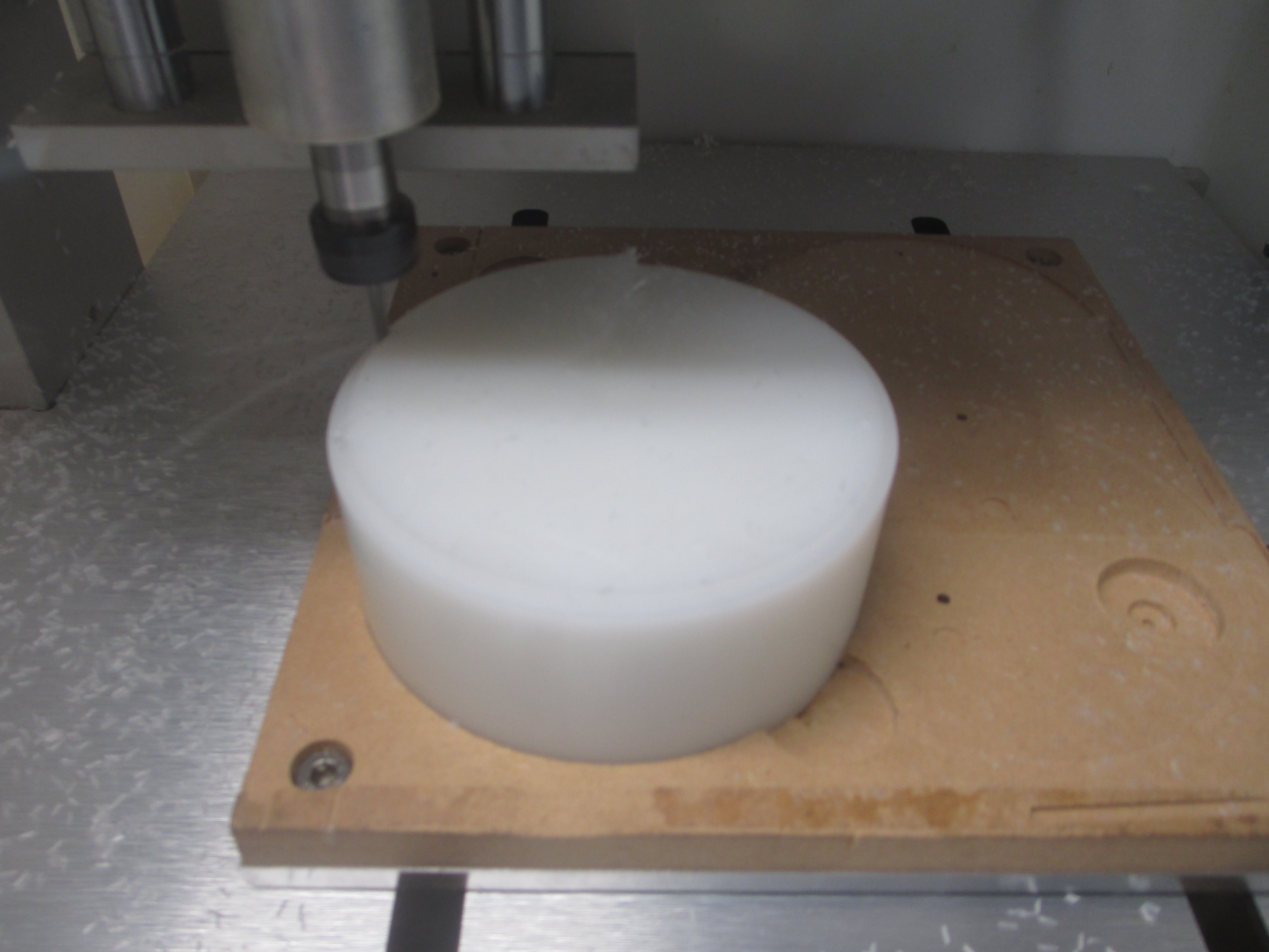
using the same socket as the last time (put in by the scheme bore, measure, rebore and test fit, repeat until proper snug fit). Again, I didn’t bother cleaning up the stock much. The ends were square enough to finish-- flat within 1.5mm stock allowance either end.
Machined the bottom side, bored holes for 3mm dowels,
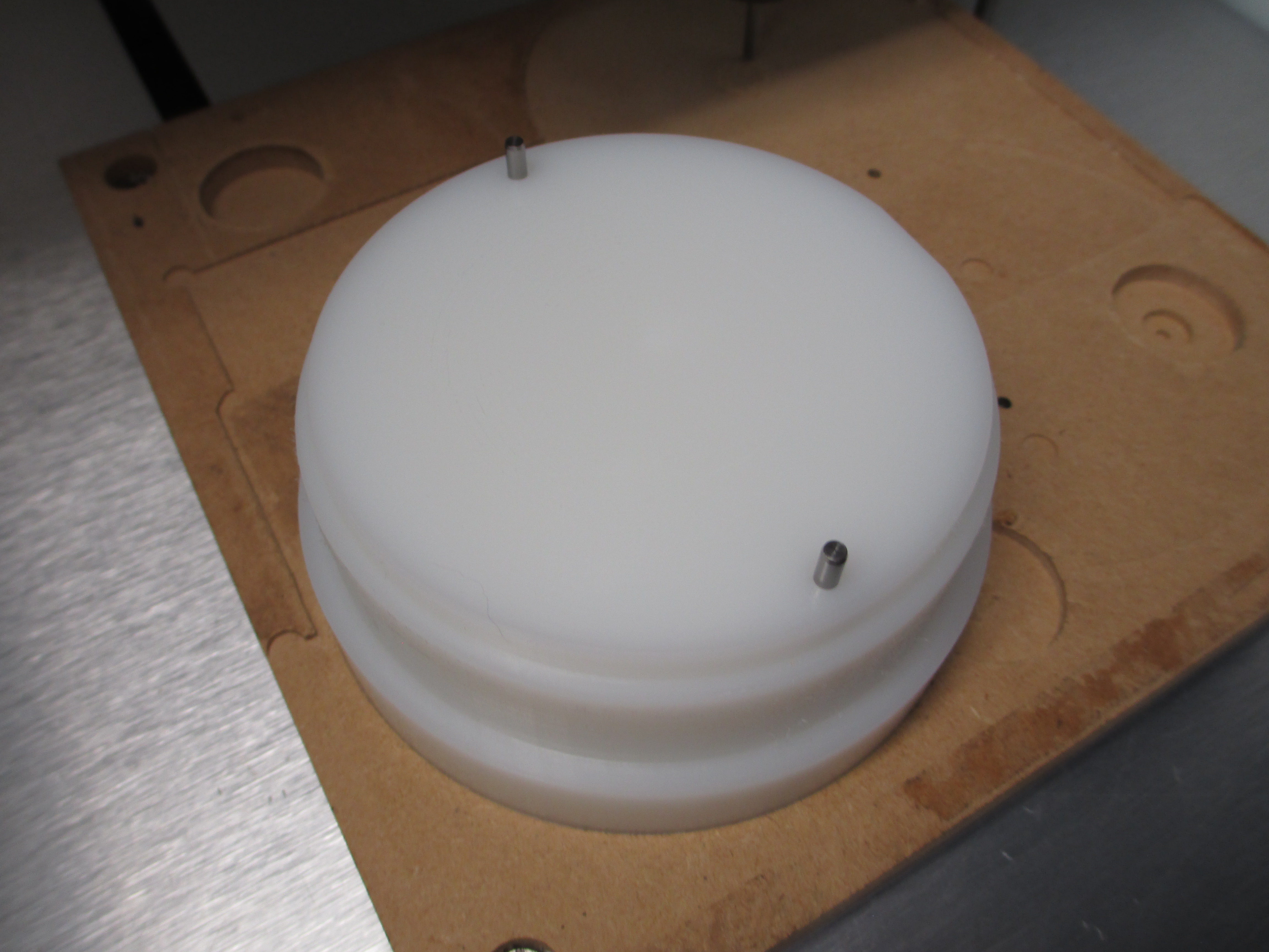
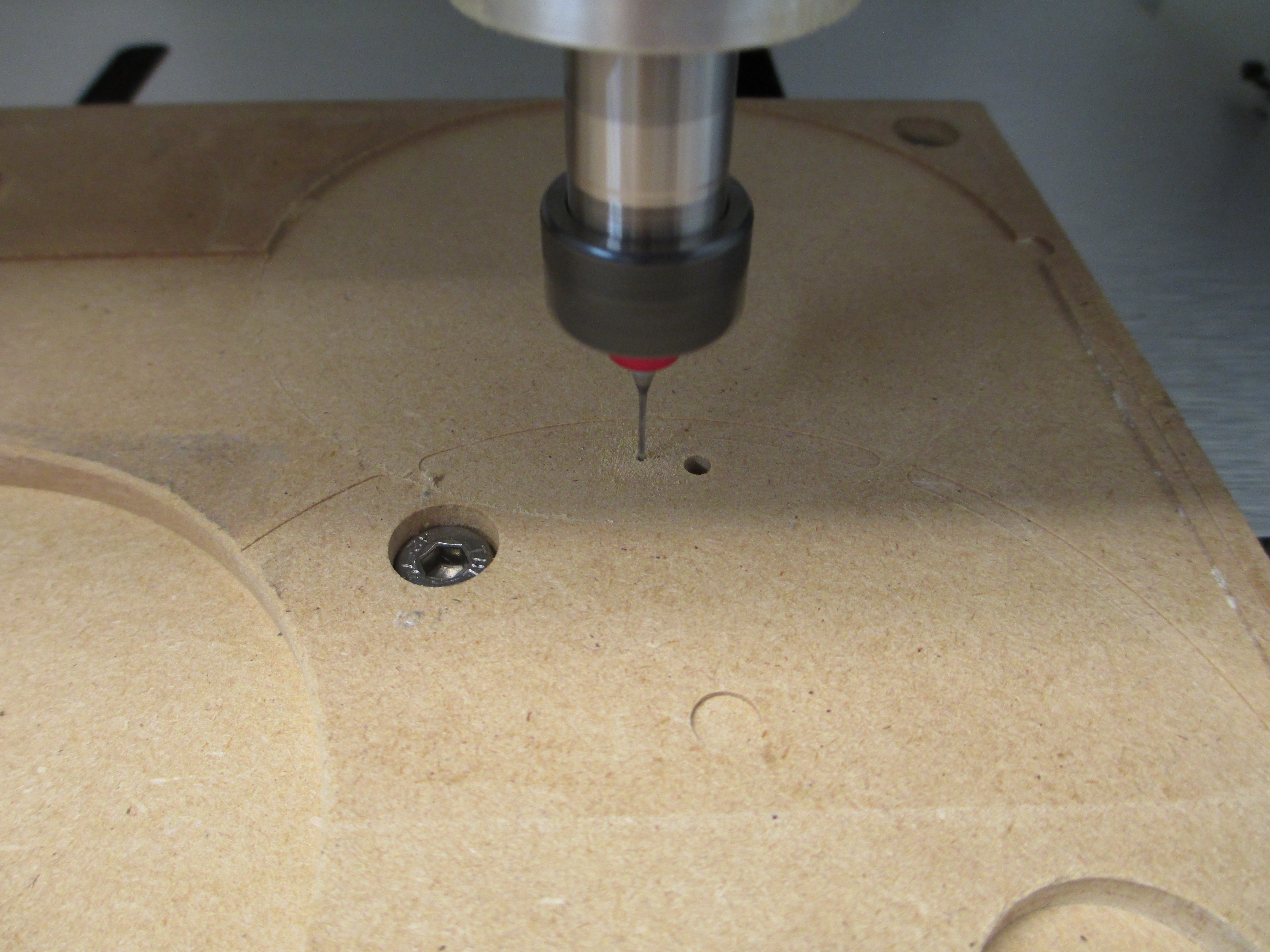
and surfaced new location for the second side mounting and bored fresh dowel holes to insure perfect zero (drill at 0.9mm, then bore using 2.4mm flat mill)

then pop in the part for setup 2 with double-sided tape to keep it down:
For both, the zero is center and at the mating surface with the wasteboard. The first setup had stock allowance on the bottom, as it was rough, so the zero was on a stock point. The second, being a finished surface, the zero was on the model. The machining on the first setup did the perimiter a bit over half way down. The second setup did the same.
Then the vee groove using a 45 degree chamfer bit
perimeter with a ball end, and a narrower vee bit (60 degree vee carving) to clearance groove the center of the vee slightly. The bit has a slight flare at the tip to make the 0.1mm flat, and in this case, it the ideal tool for a narrow clearance groove, much better than the smallest ball end I have on hand.
The product:
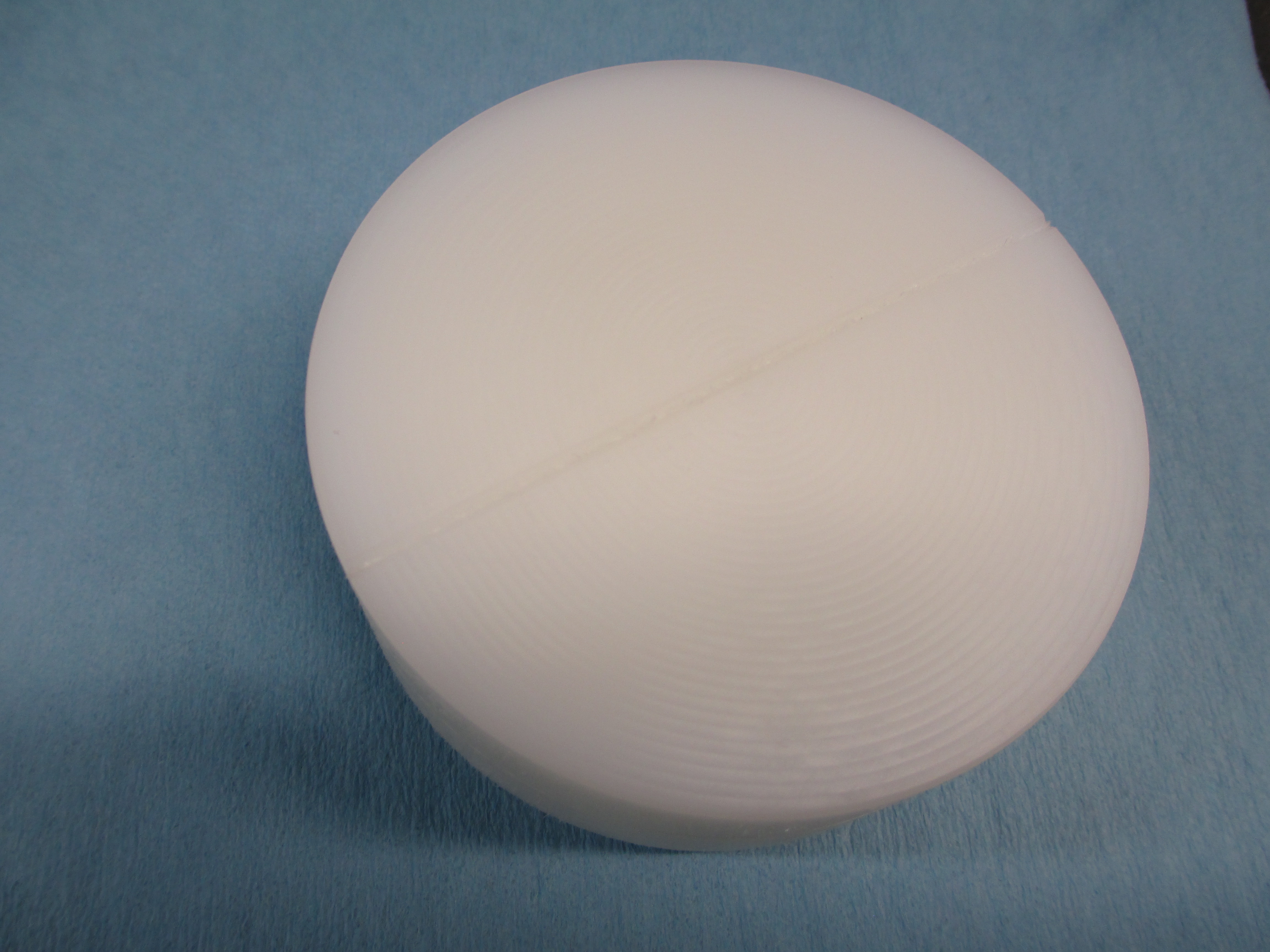
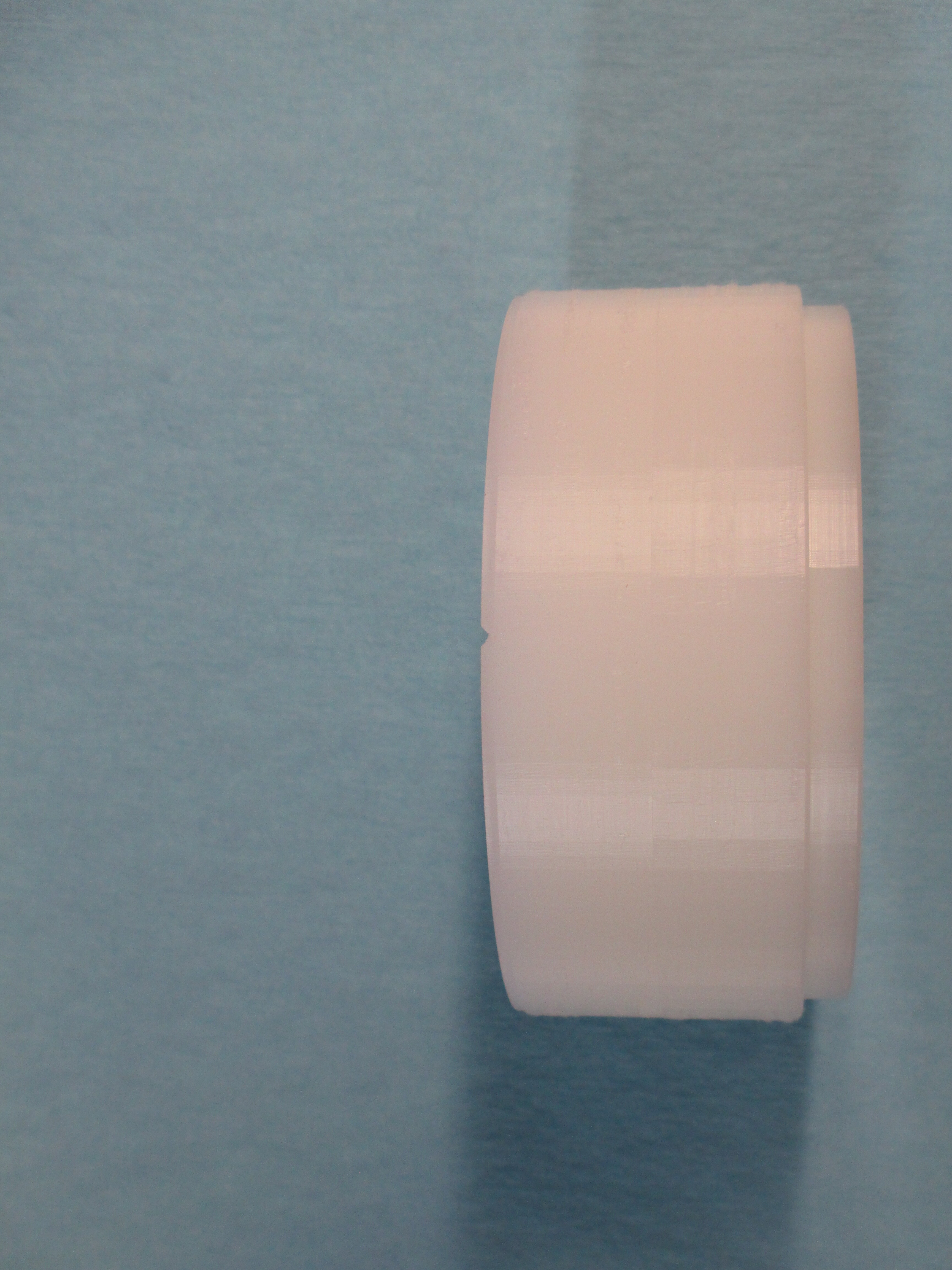
The top is dead flat though there is shadowing of the tool path. There is flat patterning due to the interpolation, but the size of the flats relative to the size of the part (100mm-ish) looks large, but the max error is less than 0.02mm on the round surfaces.
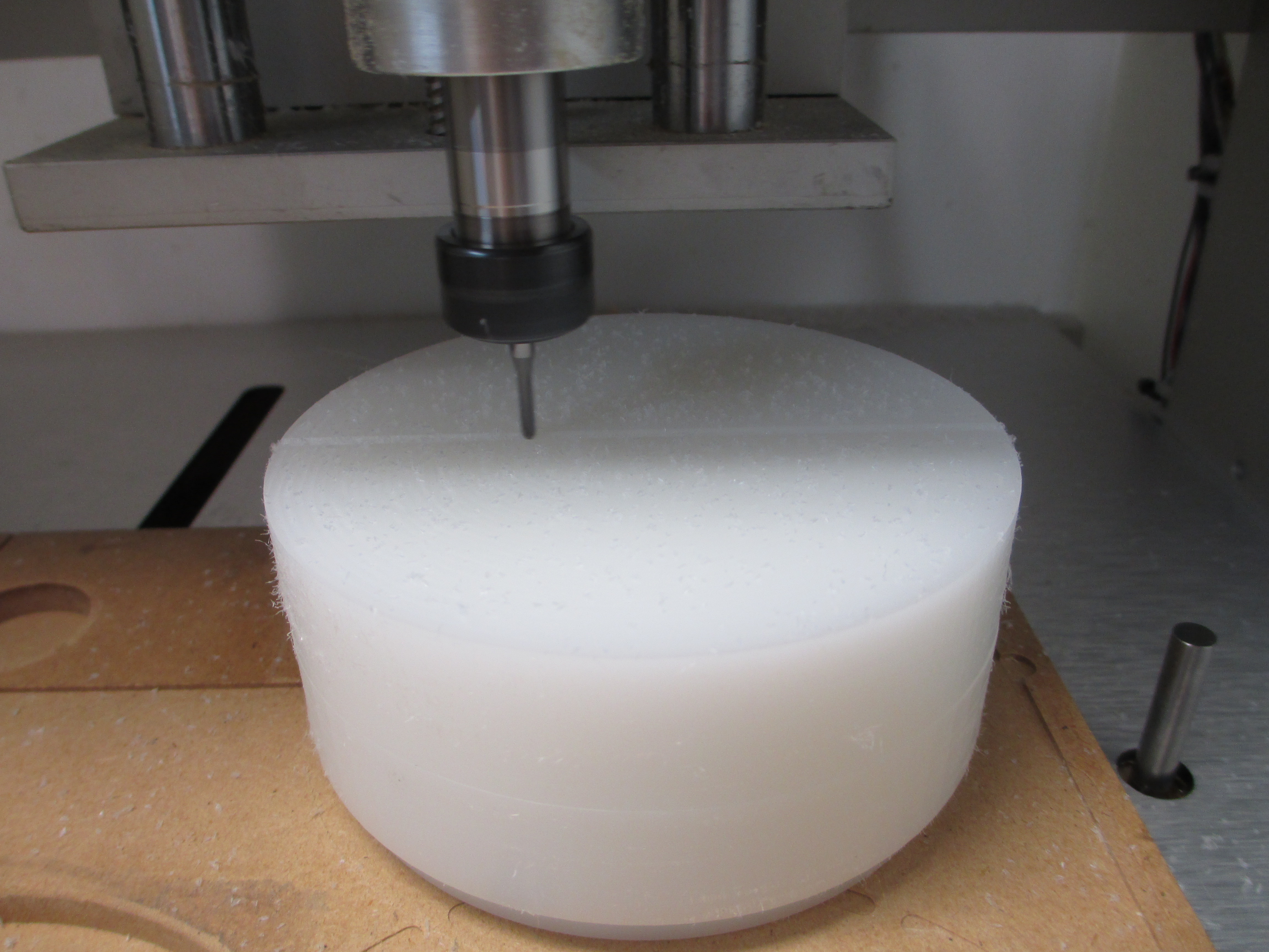
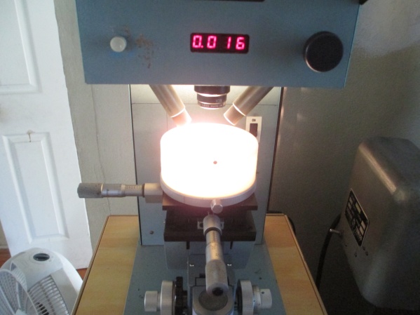
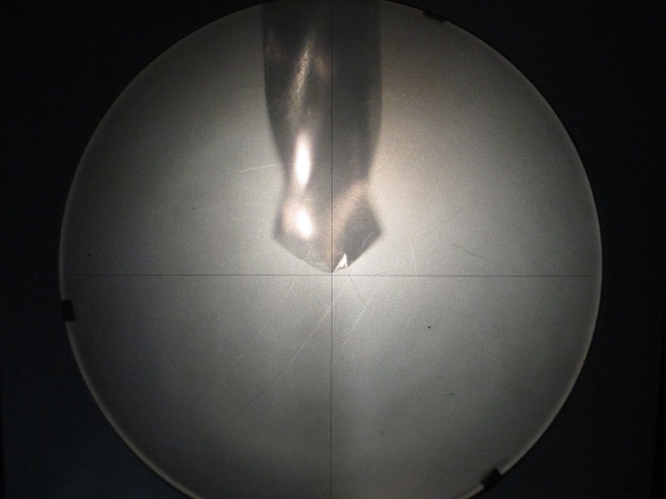
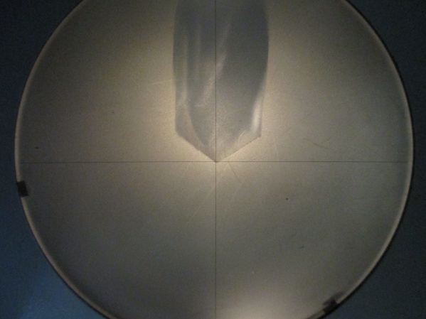
Setup on the machine with a tool for inspection (a 135deg split point drill. Done several hundred holes in T-11 chrome-moly material, looking at condition. Tough to photograph, as the HDPE is SO bright when the illumination is on):

The models and setup sheets (inventor) for those interested:
riser2-with-cam.zip (2.3 MB)
riser2-with-cam-setups.zip (2.1 MB)
8 Likes
This is my favorite project I worked on with my kid. We made iPhone cases on our Nomad 883, and our own two sided jig to help us get repeatable results.
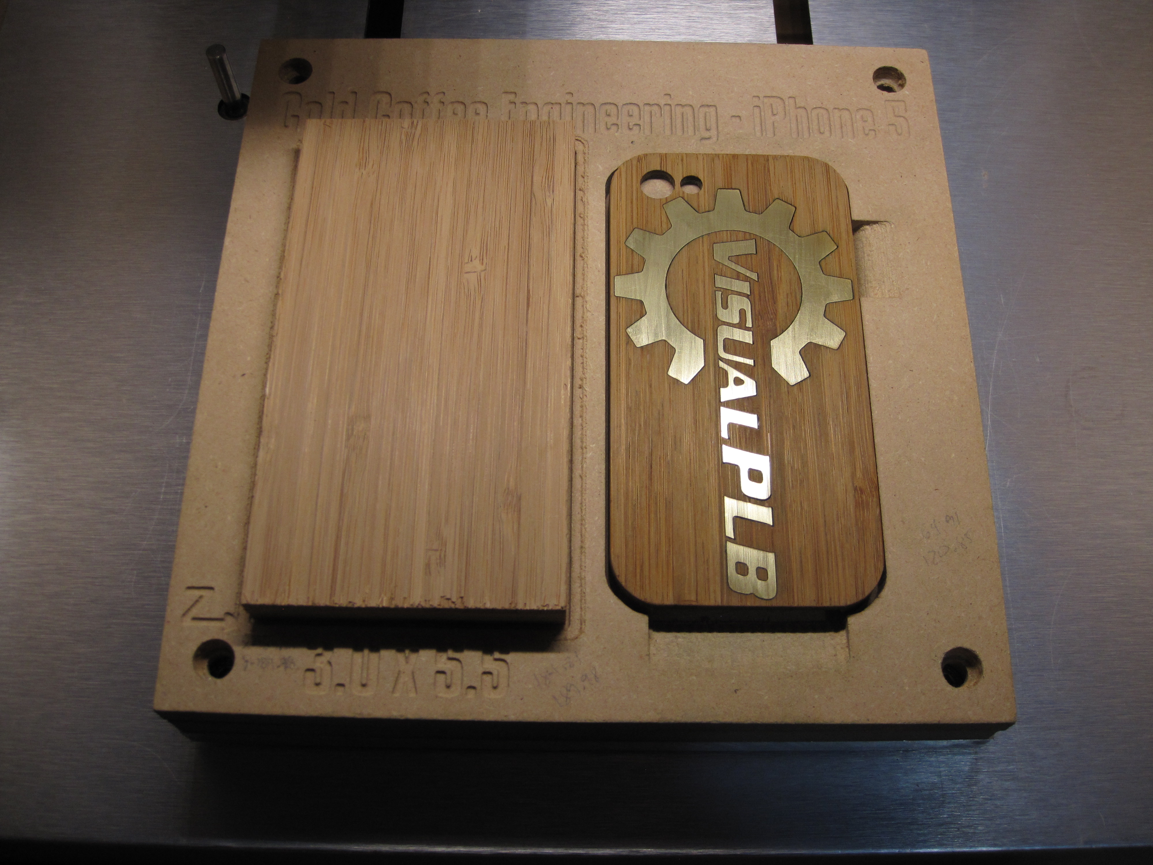
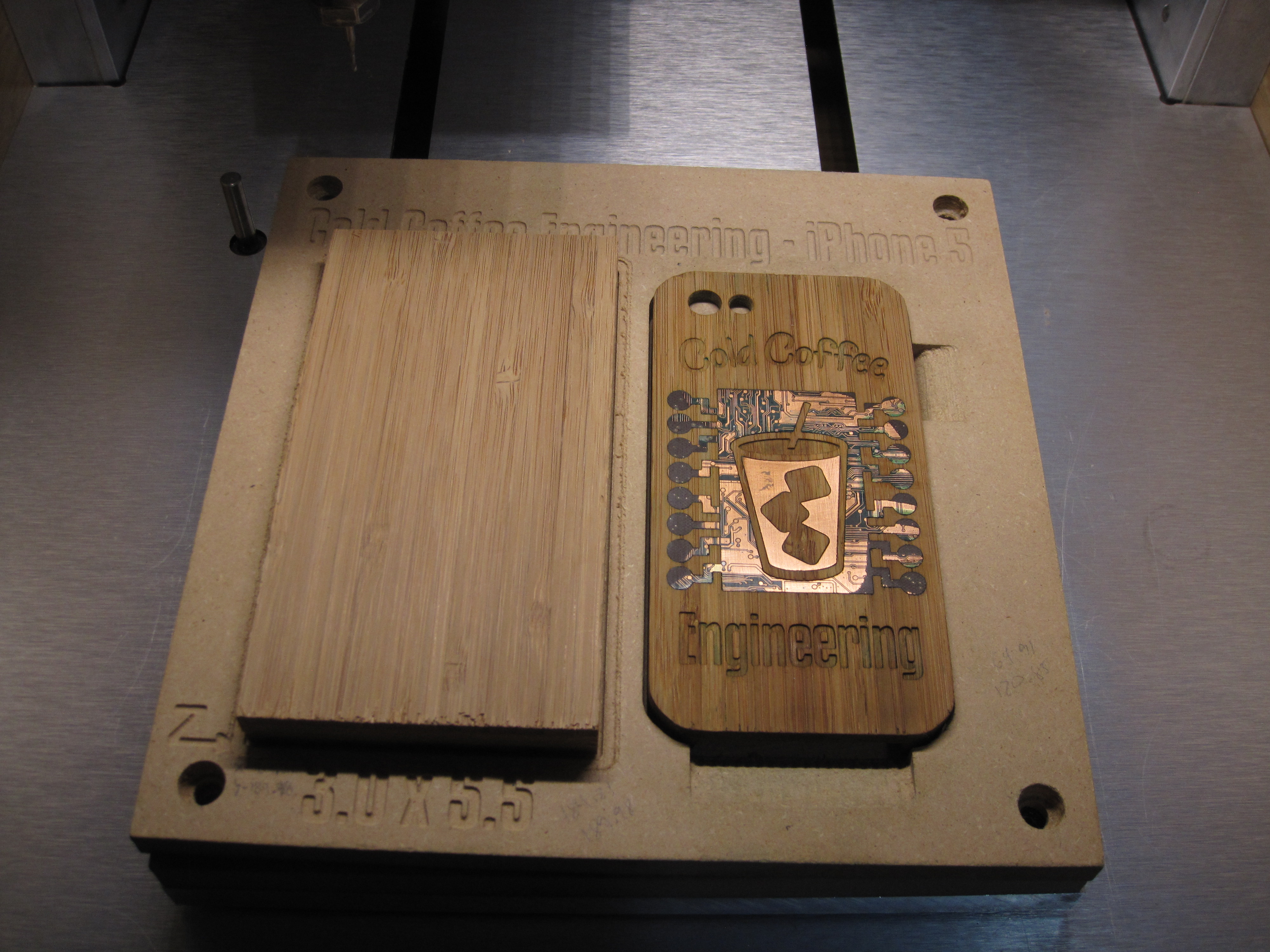
So let’s start by looking at 8x8 Nomad 883 waste board we modified. The left side of the waste board was pocketed to perfectly hold 3" by 5.5" blocks of wood (two sided tape in the middle for insurance).
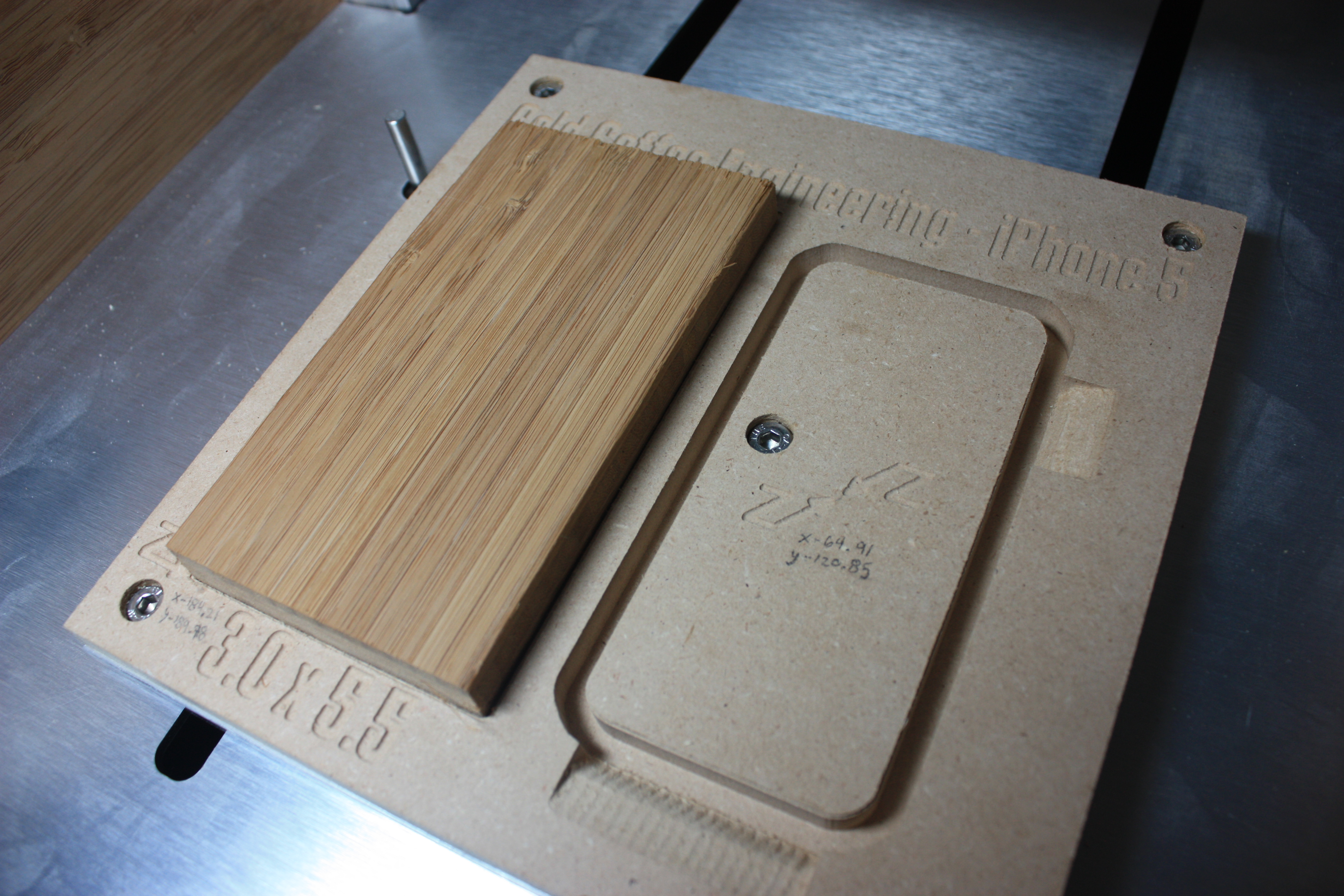
We could then CNC one side of the iPhone case.
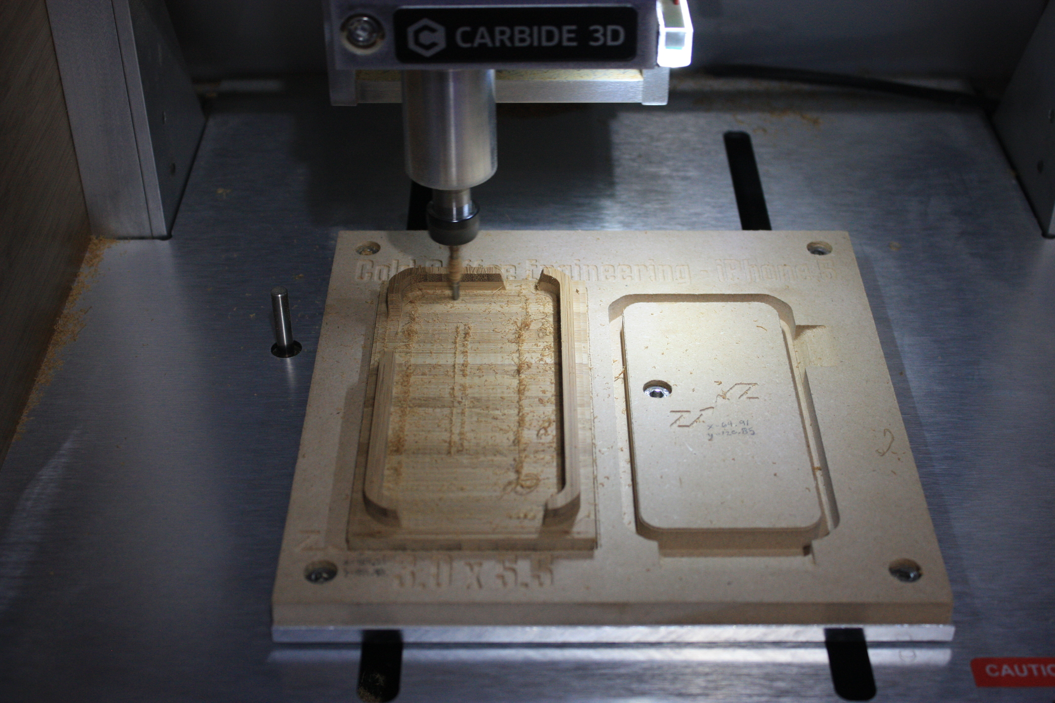
Once one side had been cut, we could flip it over onto the right side of our waste board. The slots on the right side of the waste board held the iPhone case in place so we could CNC artwork onto the back side of the case.
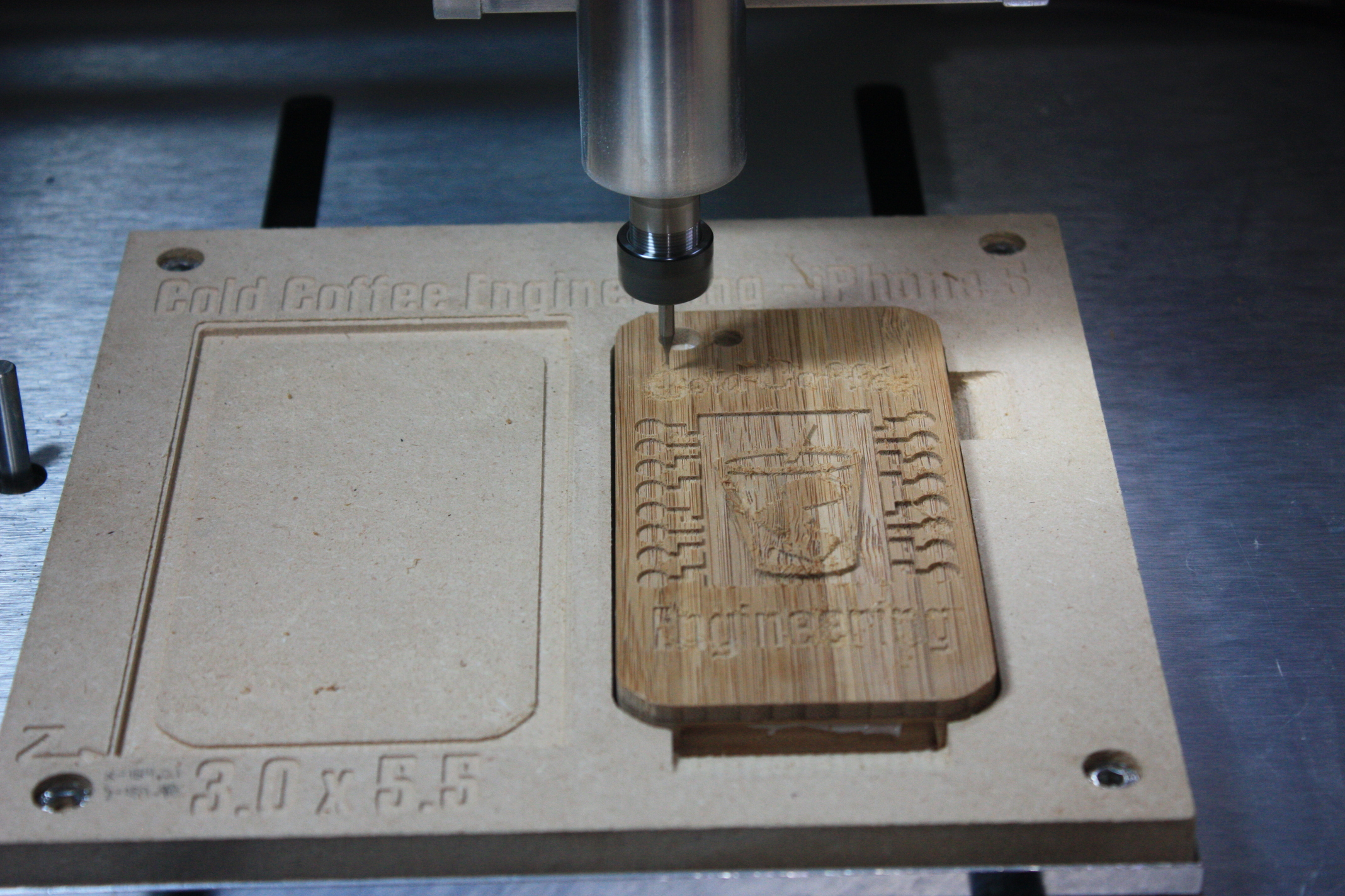
We then got into different inlay materials, and could customize cases with unique designs. The “Cold Coffee” case was my kid’s, we inlaid a circuit board that was pulled from a dead inkjet printer. And then added a copper inlay as it was somewhat like the color of coffee.
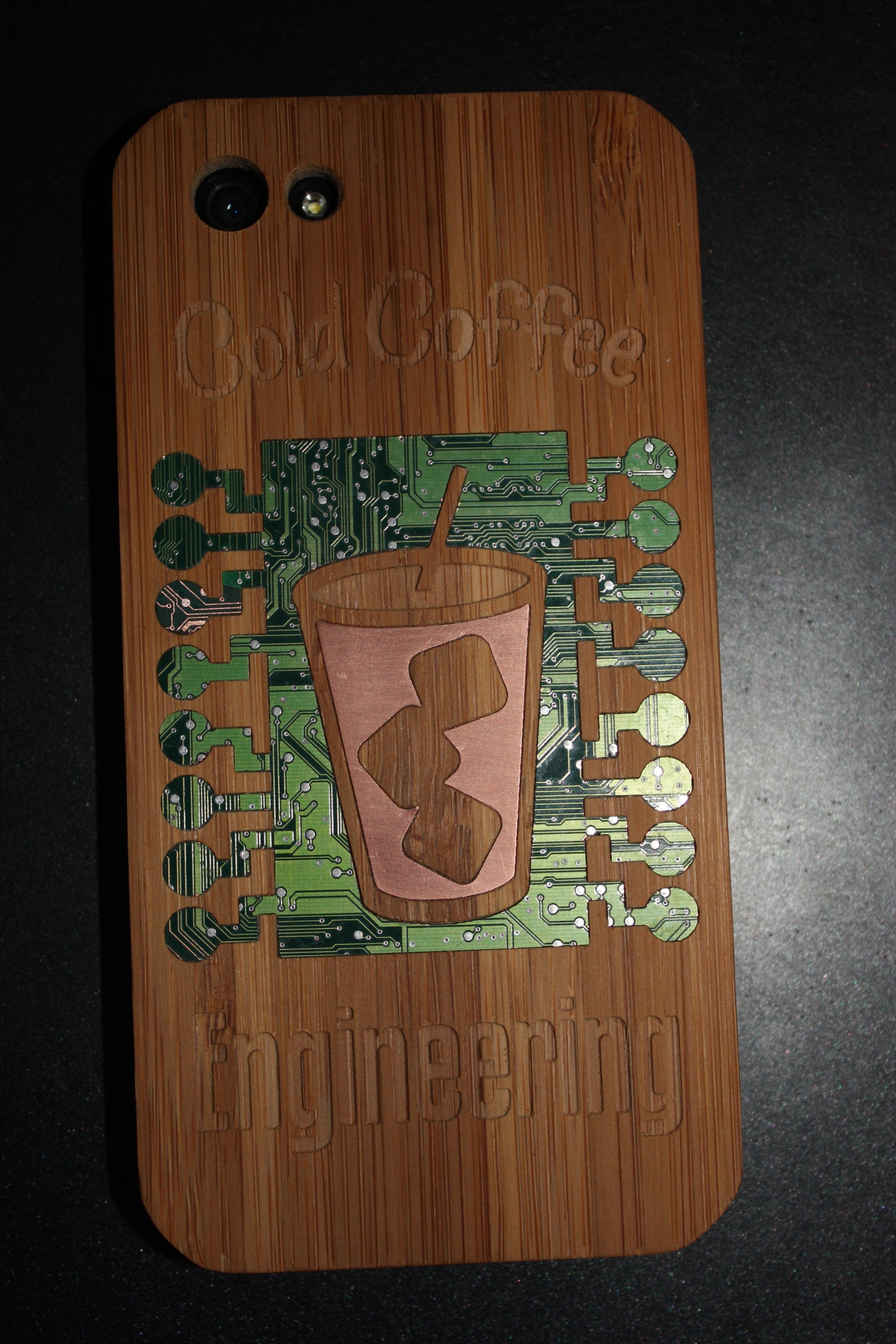
I think that case got even better looking as it aged. This is what a teenager does pulling a phone out their pocket a million times a day.
The very first photo of the “Visual PLB” case (that I took today) is my current iPhone case. I have used this case for over 2 years. I’ll admit I cleaned it up for this photo, but the brass and bamboo have held up WAY beyond my expectations. Bamboo is by far my favorite material to CNC.
iPhone5.mcf (20.0 KB)
iPhone5 PLB.zip (1.6 MB)
25 Likes
Oh boy, now I have to try “PCB inlays”, that looks fantastic
The “side by side flip jig” is very nice too 
Some love for the Shapeoko 
Watch a video of my 3 setup/ 4 bit change toolpaths here:
F360 design here:
https://a360.co/31al5O2


17 Likes
Nice ! Now you have to tell us what this is for? watercooling system ?
Looks like a hotend for a 3D printer.
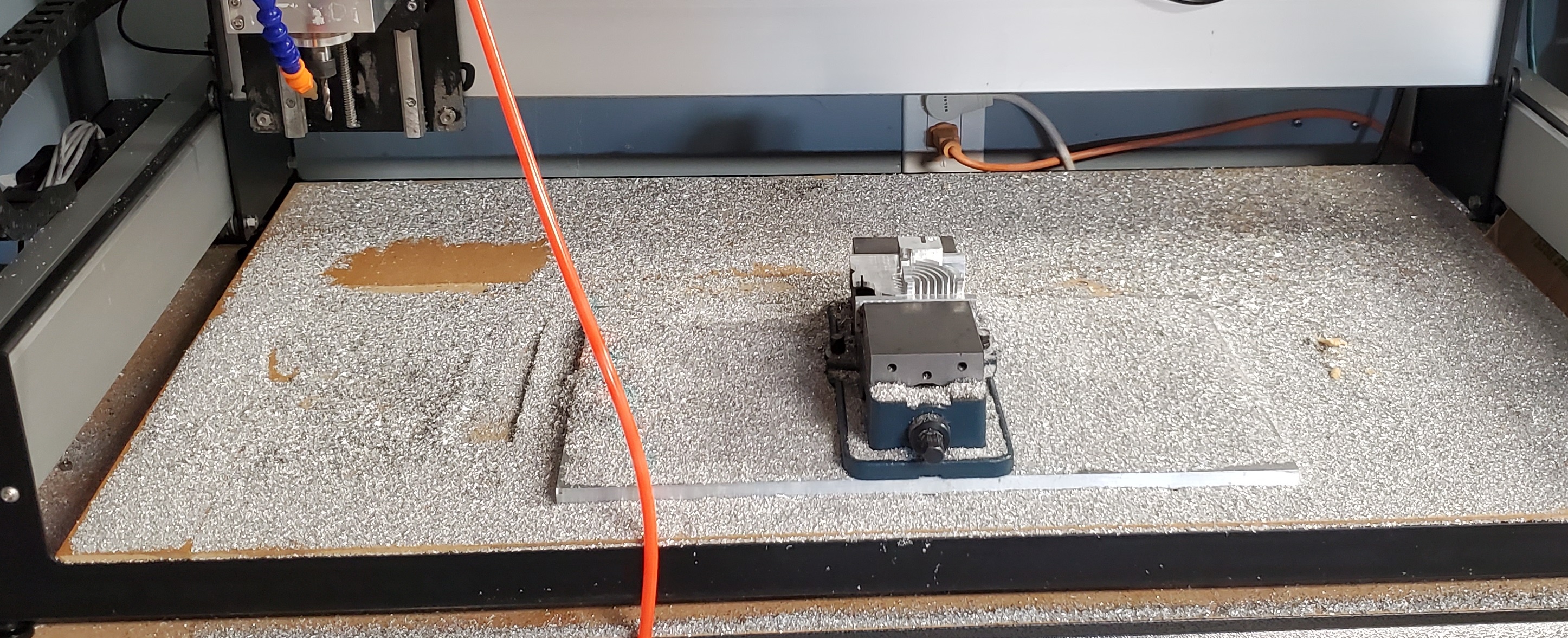
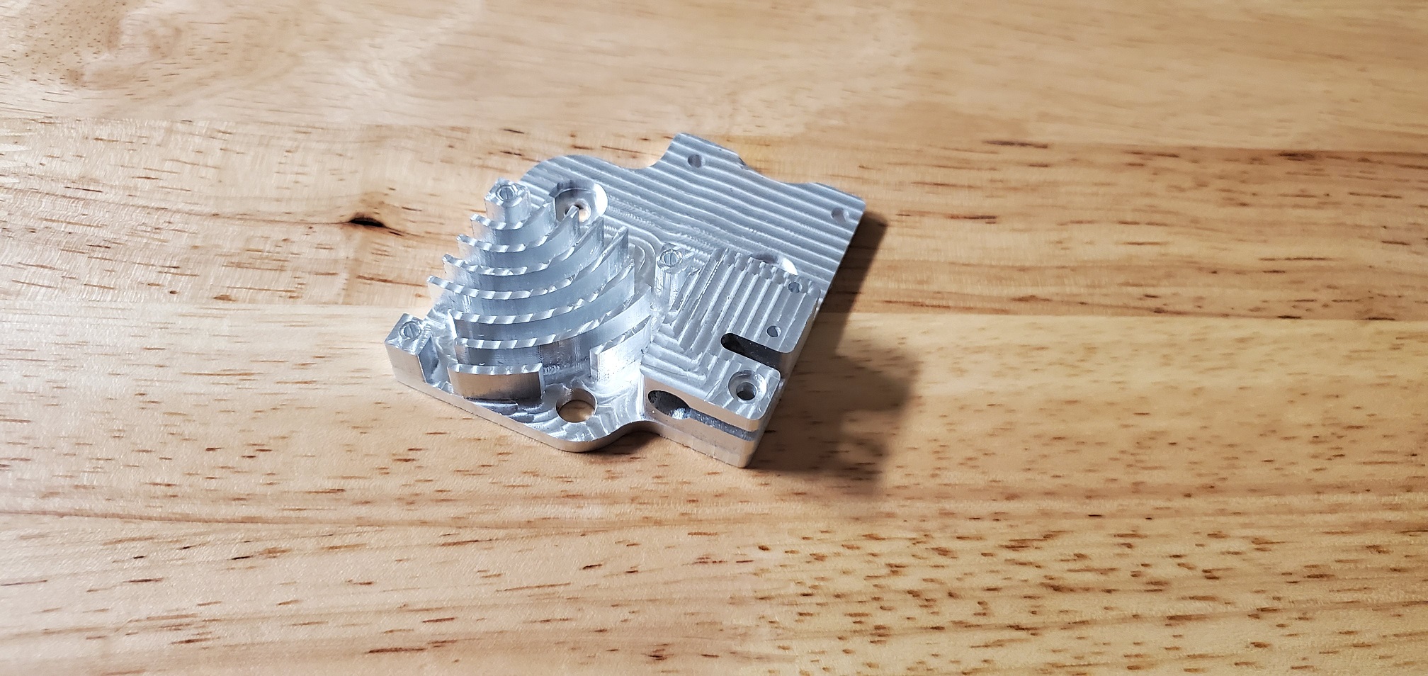
It’s an all in one x-carriage, hot end and direct drive extruder mount for CR10s and Enders. This will replace a bevy of heavy sheet metal and an underperforming stock hot end.
8 Likes
@Liquidice Awesome work! Love the cooling fins and standoffs for the fan! Any heat transfer calculations on the fins? (I mean, it looks plenty capable I’m just curious).
I might have to do something fun like this for my Wanhao i3…looks like you have the Z-Plus for your Z-axis? Looks more than capable in aluminum!
Nice work again!
Kyle
1 Like
I ran a FEA analysis in fusion 360 with a nozzle temp of 220C; outcome put fins in ~35C range with cold end of the heatbreak zone at around 45C.
3 Likes
Working for Autodesk i get so many people on CNC threads complaining about Fusion 360 and that Autodesk is trying to just take your money. But when i see someone like you take advantage of high end FEA capability to solve a problem, I get happy. There is so much value in Fusion360 beyond Modeling and CAM for such a small price. Nice work.
9 Likes
10/10. Fusion360 is an incredibly powerful tool, and when it’s time for me to move from a free plan, I will purchase a license with zero complaints.
1 Like
The more you do on F360 the more you learn how deep it goes. These competitions definitely push me into areas of F360 I haven’t explored before. I used FEA on my plastic flexture in the last competition to check on the stress points. Not free but those few trial runs that are included to get you hooked!
This time around it is …censored… and … censored… !
2 Likes
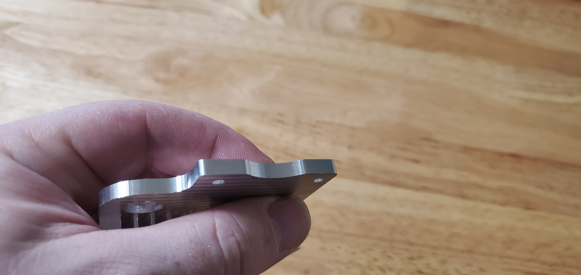
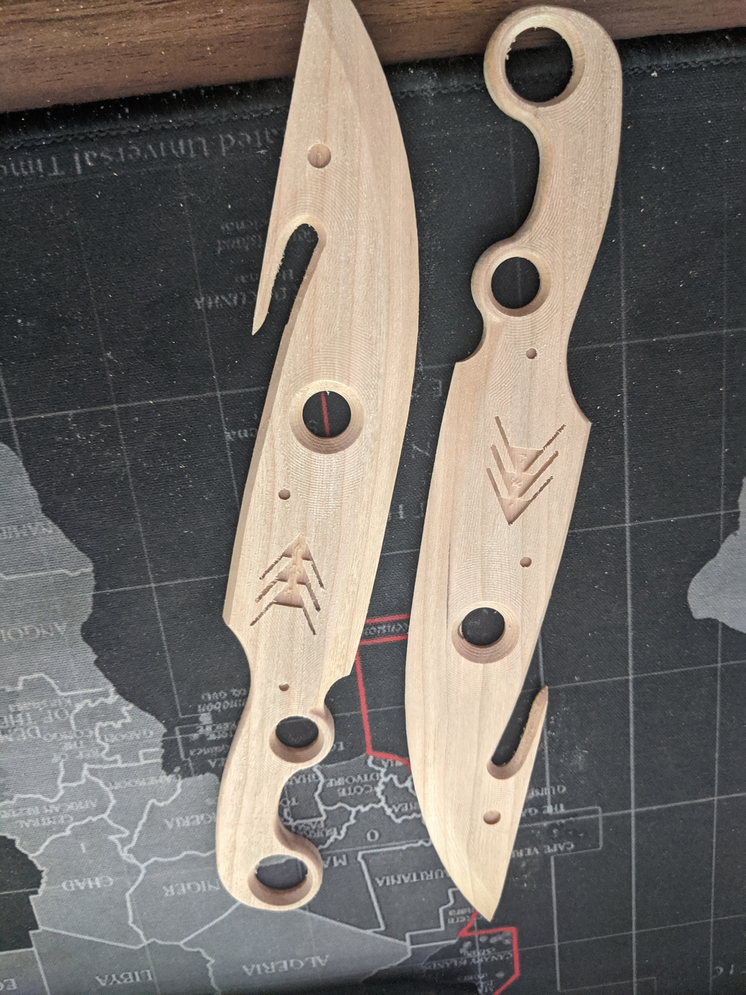
So I edited my previous post to add pictures of the 2 ghosts I just finished last night.
Also whipped this up really quick:
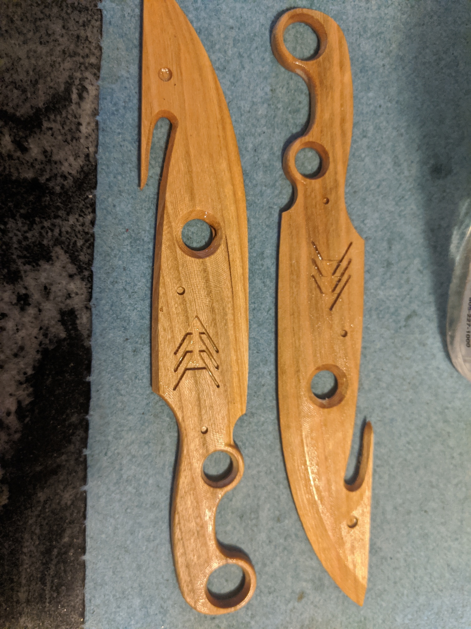
I pulled this file into Fusion: https://www.thingiverse.com/thing:684102
Scaled it down by 50% to fit the nomad, and then cut out stock from carbide create to include holes at the corners for flip/allignment.
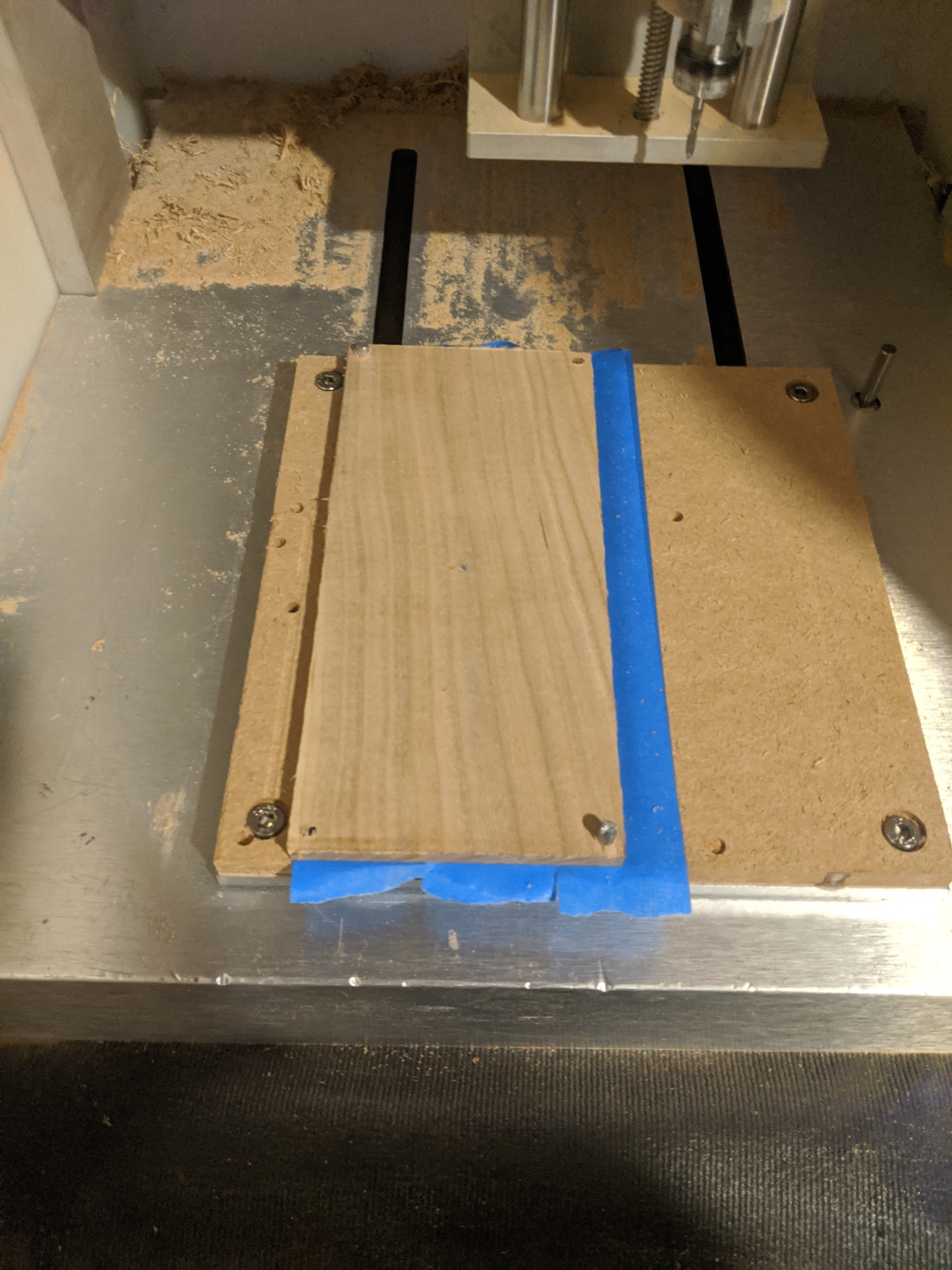
Used blue tape and super glue to hold everything down since that’s my preferred method at this point.

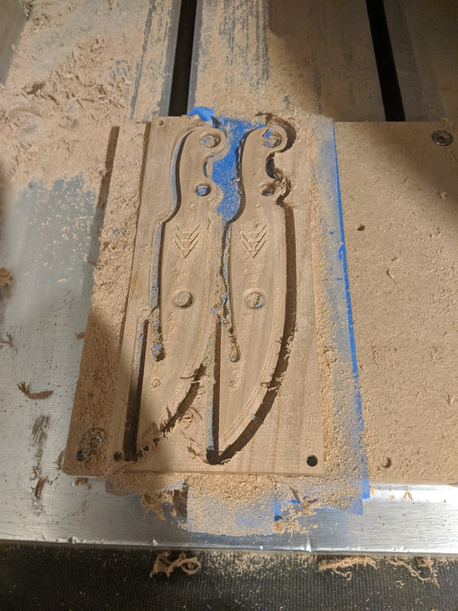
Didn’t really sand off the machine, because of laziness:
Fusion file: https://a360.co/3k3grK2
9 Likes
Got a question on the rules? Is it legit to post a project with the proprietary STL file portion removed (vcarve)? It seems that is keeping me from entering the contests and I’ve like to participate.
1 Like
It’d be something @Julien would need to weigh in on.
You could just grab something to do for funsies.
1 Like
Hi Gary,
The point of that rule is twofold
- that these challenges do not turn into “who bought the fanciest vector on Etsy and posted a picture of the awesome result”. That would sure get a lot of votes but most of the credit would go to the original Etsy artist, and that’s not the point.
- that folks get a chance to look at the toolpathing strategies used for entries.
Posting a file with the vector art removed would satisfy #2, but not #1. Also I would like to avoid some head-scratching when validating the entries for things that are “on the line”.
So to meet that rule the best would be if you can derive a non-proprietary version of your project. Replace the proprietary vectors with something similarly sized that you would create (or find, that is free to distribute), and rerun the cut ?
Alternatively, I think the C3D contests over on the Facebook group are based on “pictures-only-no-questions-asked” entries (I know this was not your question, and you may or may not want to visit the FB group, I am just mentioning this in case anyone is interested)
6 Likes
i dont know if the challenge is over but here is my entry, im still learning but im having fun. its not a difficult piece buy it the first time ive done anything thatrequired me to cut another side more less 6 sides but here it is…
i started out with a small piece of scrap that measure 1.5"x 1.5"x 1.5" . i had to build a fence on my XXL so that i could repeat the same cut 6 times. had a hard time trying to figure out hold down methods, usually working with thinner flat stock hold down is easy but this being so small was different. i think next time i’m gonna adjust the circle sizes see how much stock i can remove
7 Likes
Hi @millerasm,
The contest is still open (until Aug 2nd), thank you for your entry. Don’t hesitate to edit your post to tell us about the process you followed, difficulties you may have encountered or tips you would share, things you would have done differently, etc… ? That’s a large part of what makes those challenges interesting for others.
3 Likes