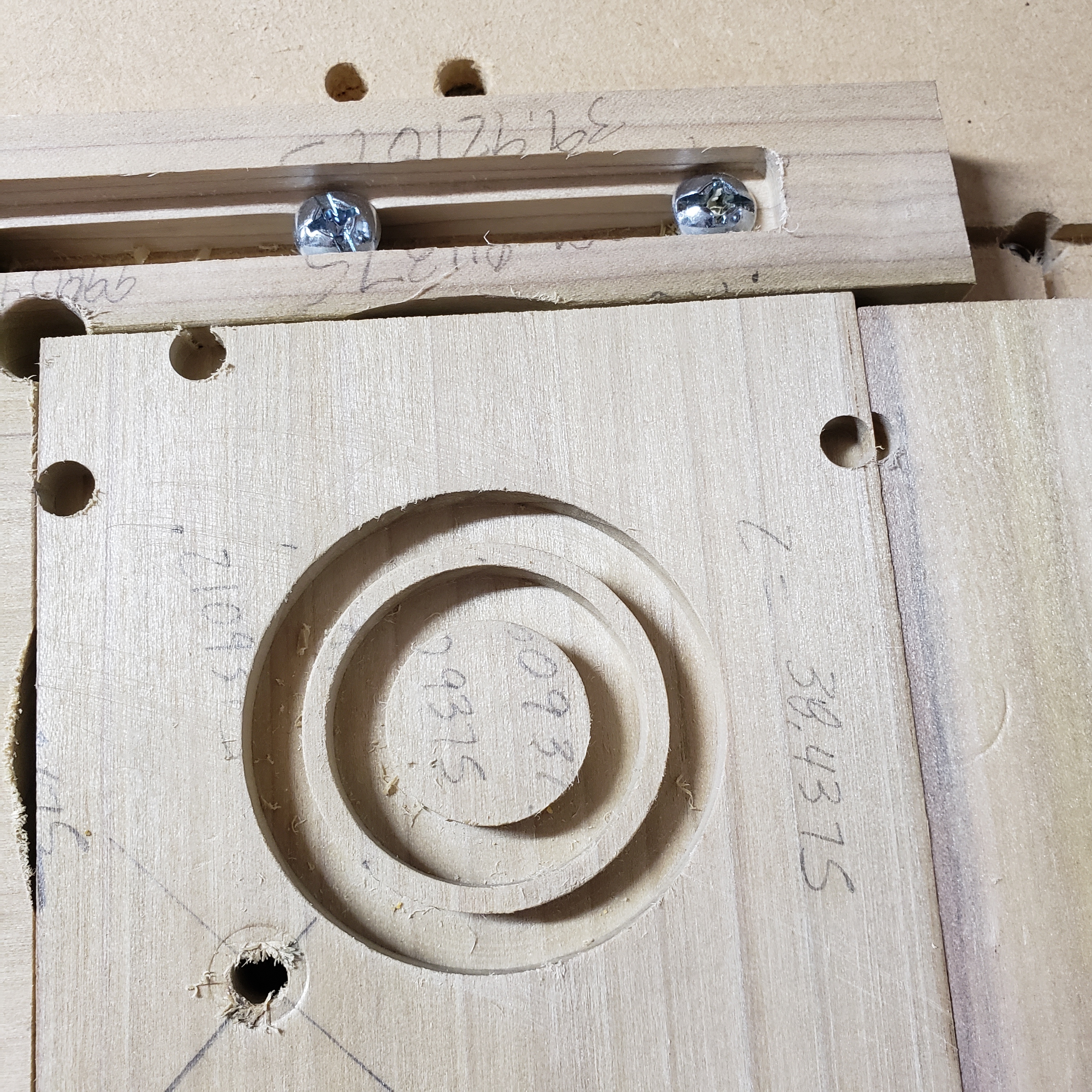
I am having issues milling concentric circles. I have had my Shapeoko 3 over a month. In the time I have pretty much taken it apart 3 times. I have squared the frame. It’s dead on. I squared the gantry. I have used the 123 blocks to square the router mounting bracket. I have milled the supplementary waste board 2x. I used the 2 end mills clamped at both ends of a small piece of wood turning in a 360° to check the router is plum. I have calibrated belt strech more times than I care to remember. I have checked and rechecked the v wheel, eccentric nuts, all bolts and set screws for tightness. Yesterday I was ready to throw it in the yard and set it on fire. I have been thru all the tutorials and watched tons of Winston’s videos and it seems no matter what I do it is not cutting the circular dimensions that I give it. So after all that explanation heres what it’s doing. In simple terms. I make a 1.7 inch circle with an outside cut. Then I drop in a 1.45 inch circle with an inside cut both at .25 inches deep. This should leave me with a .25 inch “wall” if you will between the cuts but it constantly comes in at .125 thick or less. The ID is 1.45 but the OD is roughly .125 small of the 1.7 it should be. I’m not looking for .001 accuracy here but its imperative for my application that if I say cut 1.7 inch OD circle that it does so. Any thoughts? You knowledgeable CNC guys go easy on me and use lamens terms. I am a carpenter. I dont have a machinist background. Thanks.
Have you measure the actual diameter of the bit. The often say .125 but are actually .122 or some other measure. The router bit could be flexing if you are running the bit too deep or too fast. You could also be experiencing some slop in the router bearing and collet causing some runout that you are not compensating for.
You will need to test all these things with a micrometer to find out what is really going on.
- Measure the outside diameter of the bit and make sure you have the software setup right
- Cut a simple slot pass with the bit and measure that slot to see how wide it is
- The runout measurement if more difficult if you are not used to using measurement tools but try 1 and 2 to see what you get.
are you sure about your geometry math?
I think you’re building this based on your description (but you did not say radius or diameter)
    <------------->  1.7"
----|  |-------|  |----
        <----->    1.45"
and that leaves 0.25"… FOR BOTH of the gaps combined
so each gap would be 0.125" ???
if I understood you wrong, which is quite likely, could you make a similar diagram?
I am using a .25 end mill. Which I just measured the slot and it measured .266. As for the circle. The outside diameter should be 1.7 and the inside should be 1.45 leaving me with .25 wall. The inside measurement is correct at 1.45 but the outside is .125 to small. So on the inside cut it cuts correctly but on the outside cut its cutting smaller than the number entered in the program.
lets say we walk from left to right straight to the middle of your picture… you walk through 2 of your “walls”. The sum of the width of these walls is your 1.7" - 1.45" = 0.25… so each wall is 0.125"
also if this is carbide create, could you attach the file?
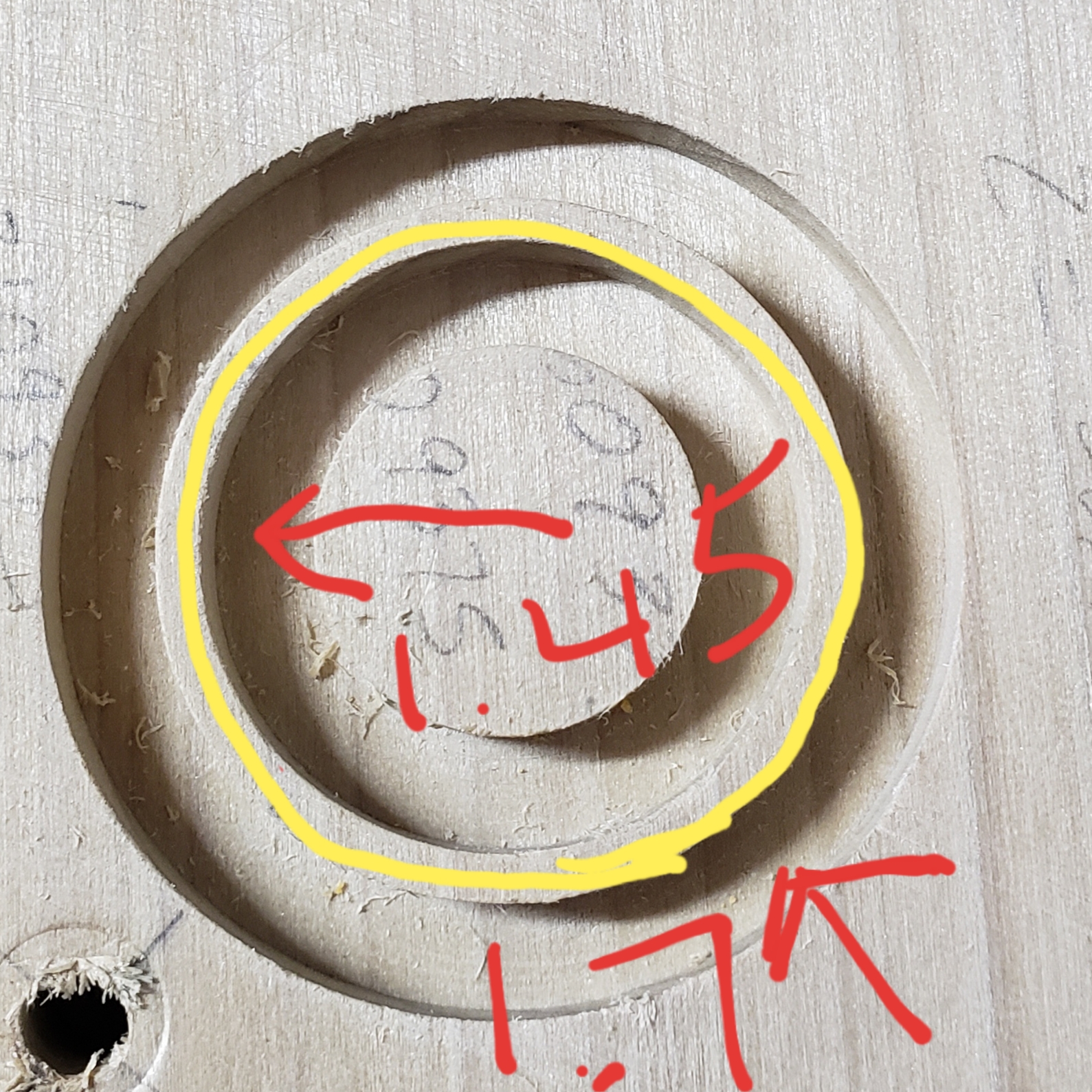
Ok. To make sure we are on the same page. I make and inside cut tool path at 1.45 inches. Then an outside cut tool path at 1.7 which leaves me with the yellow ring or “wall” which measures correctly inside but incorrectly outside over all.
I will try and attach the file. I’m currently on my phone. My laptop is in my shop
Maybe your sequence, or which path you choose (inside, outside, pocket, or on the line)
Do you set your outside dimension and assign to cut outside. Then set your inside dimension and set it to cut inside?
Did you maybe leave a 1/8” end mill selected when you set up the operations?
There are a couple of things which influence size:
- endmill selection
- toolpath assignment
- climb vs. conventional milling
- belt stretch calibration
It is best to try to address one thing at a time — work from large -> small — I’d suggest starting with belt stretch calibration. The easiest way I’ve found to do that is to use a V endmill to V carve circles just a little less than your calipers can measure — use an endmill which is more obtuse than the pointed tips of your calipers, then use them to measure at the bottom of the holes.
Once belt stretch is squared away, work out endmill and toolpath — cut a slot and measure it — that should give you your effect endmill diameter — cut a pocket or island that dimension, but leave a roughing clearance and take a finishing pass, then measure — do the opposite (island or pocket) and see where you end up.
I usually drop my circles in at the proper demensions and then assign a tool path starting with the inside circle first.
I just tried the same cut, soft pine, 0.25 flat end (supplied with the XXL) 1.7"outer 1.45 inner and came out with this.

I will try this Will. Thanks
David. No I wish it were that easy.
With Carbide Create you input radius not diameter. A 1.700" diameter and .1.450" diameter will leave a .125" wall ((1.700-1.450)/2=.125). A 1.7" radius and .425" radius will leave a .25" wall ((3.400-2.900)/2=.250)
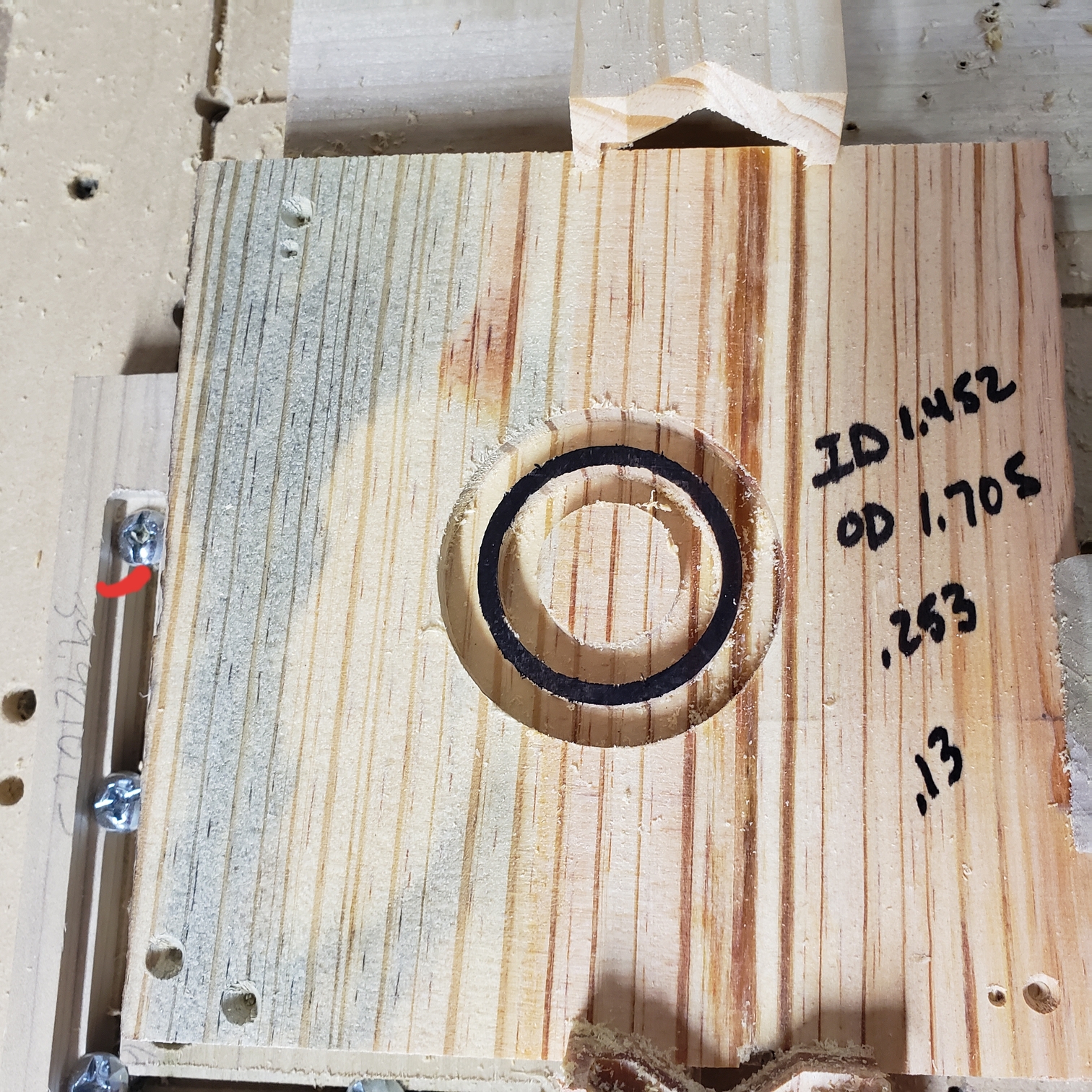
I should have added that the thickness is measuring. .125 to .13 depending on where I measure the ring.