I went through calibrating the x and y axis. It was off by a very small amount and I am adjusting $100 and $101 to compensate.
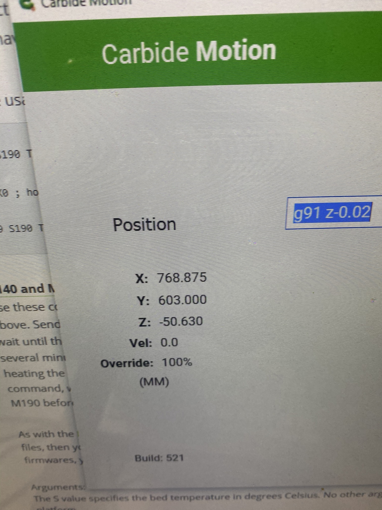
I then used my 123 blocks to determine whether the z axis on the stock Shapeoko Pro needed calibrating. I zeroed the router mount with two of the 123 blocks stacked on top of each other. I then removed 2” worth of 123 blocks. The distance that the z axis should have travelled down is 50.8mm. However the z axis only traveled down -50.63 (according to carbide motion). I tested this multiple times.
Additionally, when cutting MDF, the end mill has cut into the spoil board which aligns with the z axis being off.
I just wanted to validate with the brains trust that $102 is the value I should adjust and that even though the z axis is not belt driven, it also requires the calibration.
In theory yes ($102 is the way to go), and while I would expect the leadscrew/ballscrew Z axes to not usually require much calibration if any, I never owned a Z-plus (or its SO Pro variant) so it’s not impossible. I am a little surprised by the 0.3% error in your test case, but can’t tell if that is typical.
Anyway there is no harm in modifying $102, I would maybe just do two more tests:
checking whether there is any backlash on your Z. Depending on the way you measured it may or may not be included in the 50.63mm result. If the difference to 50.8mm happened to mainly to due backlash, there would be no point in adjusting the number of steps per mm.
repeating your test for various shorter and larger travel distances. If the calibration factor you get is roughly the same in all cases, then it’s a good case for adjusting $102, if not then you may enter an endless tail-chasing loop where the perfect calibration for a small distance is off for the longer moves, and vice versa. I have spent a ridiculous amount of time obsessing about calibration (this, was probably the best example of me going way too far), I now run my machine with the default steps/mm on all axes and compensate (when needed) at CAM level.
Thanks for the reply. I had seen in previous posts your hesitation to people calibrating based on some experience, but had never seen your quest for perfection.
Btw…I’m thinking that the mouse calibration contraption could definitely win a calibration community challenge . It’s awesome.
Also, as I went through that old post I became thoroughly confused about how Will Adam’s has anytime to post on these forums, given that he reads so much.
There is sometimes variation in leadscrew, typically less than half a percent. I would add that in your testing to make sure there’s not any backlash in your method. IE:
Lower spindle until touching 123 blocks.
Remove single 123 block.
Lower spindle until touching bottom block.
NOT:
Raise spindle until it clears 123 Blocks
Remove single 123 block.
Lower spindle until touching bottom block.
You want to ensure all measurements happen without a reversal in direction of the axis. Otherwise you might add in a non-linear effect into your calibration and end up worse off.
I ask because not only have I had to set my $102 to 198.8 but I also see I lose 0.02mm to backlash, is this typical? Also, I see no way to adjust it.
Is there less backlash with the HDZ than there is with the Z-plus? Is the ballscrew of the HDZ more precise than the leadscrew on the Z-plus (in terms of ‘steps per unit of measurement’)?
Hard to say, lot of little things can contribute to it like how tight the tolerances are for the stepper shaft being held in the motor vs the dual angular contact bearing system supporting the ball screw in the HDZ. Or the leadnut vs ball screw nut. But you’re kind of splitting unnecessary hairs at that point. 0.02mm is basically negligible for a mechanical system and well within the margin of error for any CNC under $20,000.
@wmoy Ok, thank you. Also, I appreciate your videos!
I wanted to make a correction to the above, I went back and re-measured using only the mdi interface and digital calipers (also with z-axis dial setter) and found my z-axis backlash is ~0.04mm (meaning my measurements are 0.04mm short when changing directions along the z), and my $102 value is 199.3…
Method:
-Clamped the head of the calipers to the spoilboard (leveled 1.5" HDPE attached to 5/8" ATP5 aluminum plate base)
-The moveable jaw of the calipers rested on the top surface of the spindle mount ~5mm from the abutment with the Z-axis plate
-Lowered the spindle mount towards the bottom end of the Z-height range (-2mm past what would be zero)
-Jogged up 2mm (2 times press the 1mm increment)
-Zero both the Z-axis in the Jog window as well as the digital calipers
-On MDI tab input typed in “g1 z50 f200”
-Noted that everything reported movement of 50.00mm (both calipers and Carbide Motion 521)
-On MDI tab input typed in “g1 z0 f200”
-After Z-axis motion completed, very carefully pushed the caliper jaw down to rest on surface of spindle mount
-Noted the digital calipers now reported height of 0.04mm, this is the backlash.
This was repeated 4 times, every time the same (with $102=199.3 for my Z-Plus).
Should I be concerned about 0.04mm backlash? What would be outside of margin of error for you?
short answer = No.
0.04mm / 0.001574803 inch
Pretty close and from what I read within expected tolerance for this machine.
Besides, (except for engraving bits) it will take around double that just to get a bit to start cutting.
Any mechanical linkage assembly will have some play. Otherwise it would be so tight it could not break friction to move.
 . It’s awesome.