New to CNC. I have been trying to do my first serious inlay. Simple, one piece inlay. I was having problems with gaps around the edges, so I tried a series of test pieces cutting the inlays and pockets at different depths to see if I could find the sweet spot. BUT, I consistently get gaps especially at the bottom of the pattern. Could tramming be a problem? It is slightly out of whack, but I didn’t think it was enough to cause problems, other than a little extra sanding. Thoughts? Thanks in advance.
Which machine?
Photo of the inlay and parts?
Upload the file?
One should definitely tram the MDF if there seem to be part alignment issues.
I am by no means an inlay expert, but I have had some success and some failures.
Here’s what I have learned.
- Tram your machine.
- Surface your wasteboard
- Surface both the base and the plug of your stock before you carve.
- Let it rest for 24 hours after you carve and before you glue it up.
- Use SHARP/NEW bits.
- Spend as long as it takes to “clean up” the carve. I use an exacto knife to remove all the fuzzies. Also, trim down the very thin points/fins. I like to put a 45-degree angle on them.
- Use a 12.4-degree V-bit. 46280-K and a .125 or 3/16 clearance bit.
- Carve slowly, don’t push limits.
- Do a test piece first, MDF is way cheaper than Walnut.
- If the plug is too loose, bump the angle of the bit up slightly within the tool database. i.e., go from 12.4 to 12.6; if the fit is too tight, go from 12.4 to 12.2.
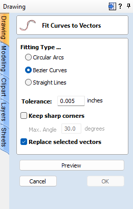
- Remove all sharp points from the vector. Use the Fillet tool to “dull” sharp points; it’s wood, not metal, so there’s no need to use a point. Vectric has a tool that can handle the entire project at once.
- Skip super fine detail.
Practice, Practice, Practice.
If your gaps are only at the bottom, and not on the sides, try a test mirroring your design for the male vertically instead of horizontally. Or just tram the machine & do another test, as tram is a pretty likely suspect.
1 Like
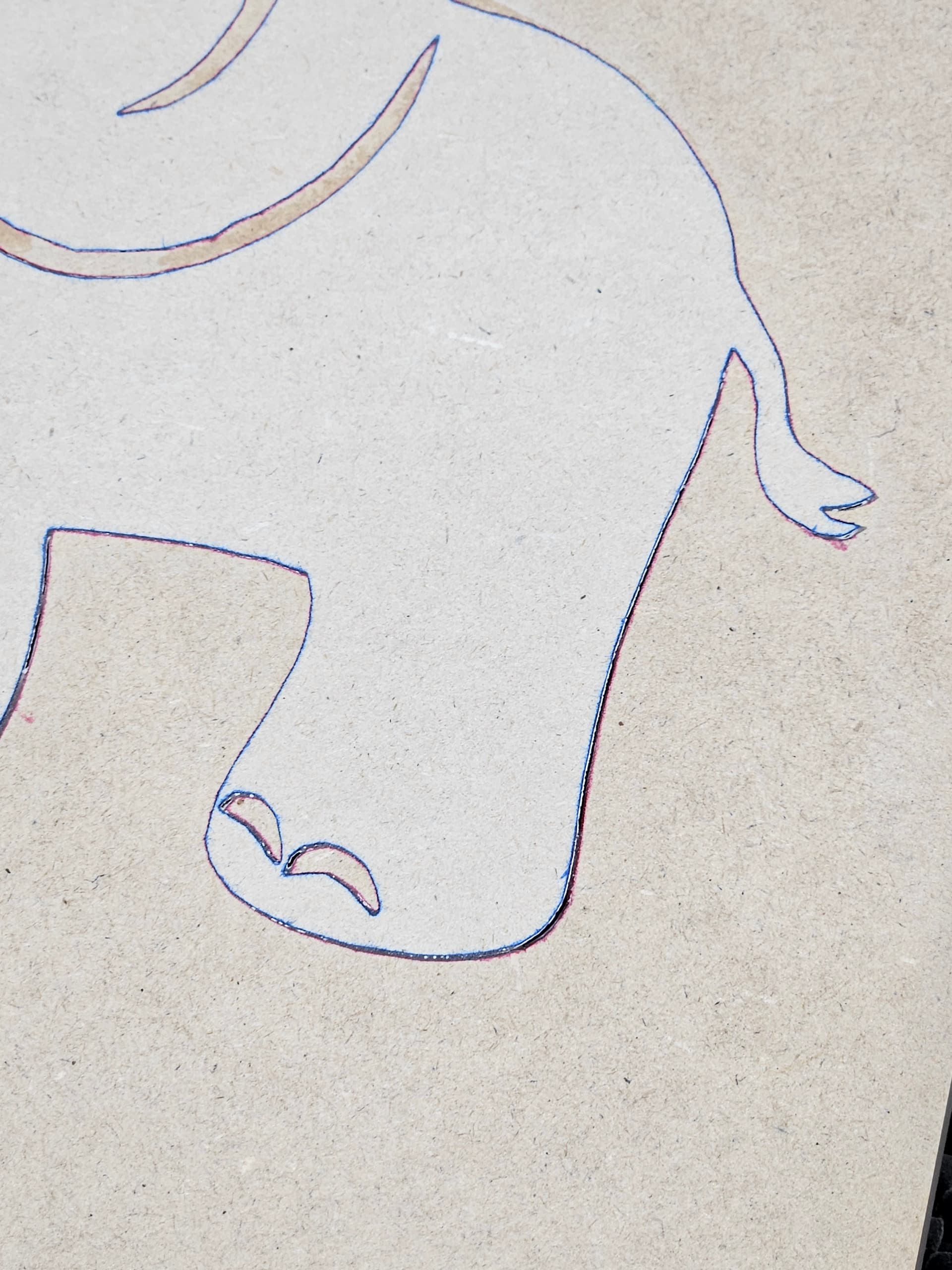
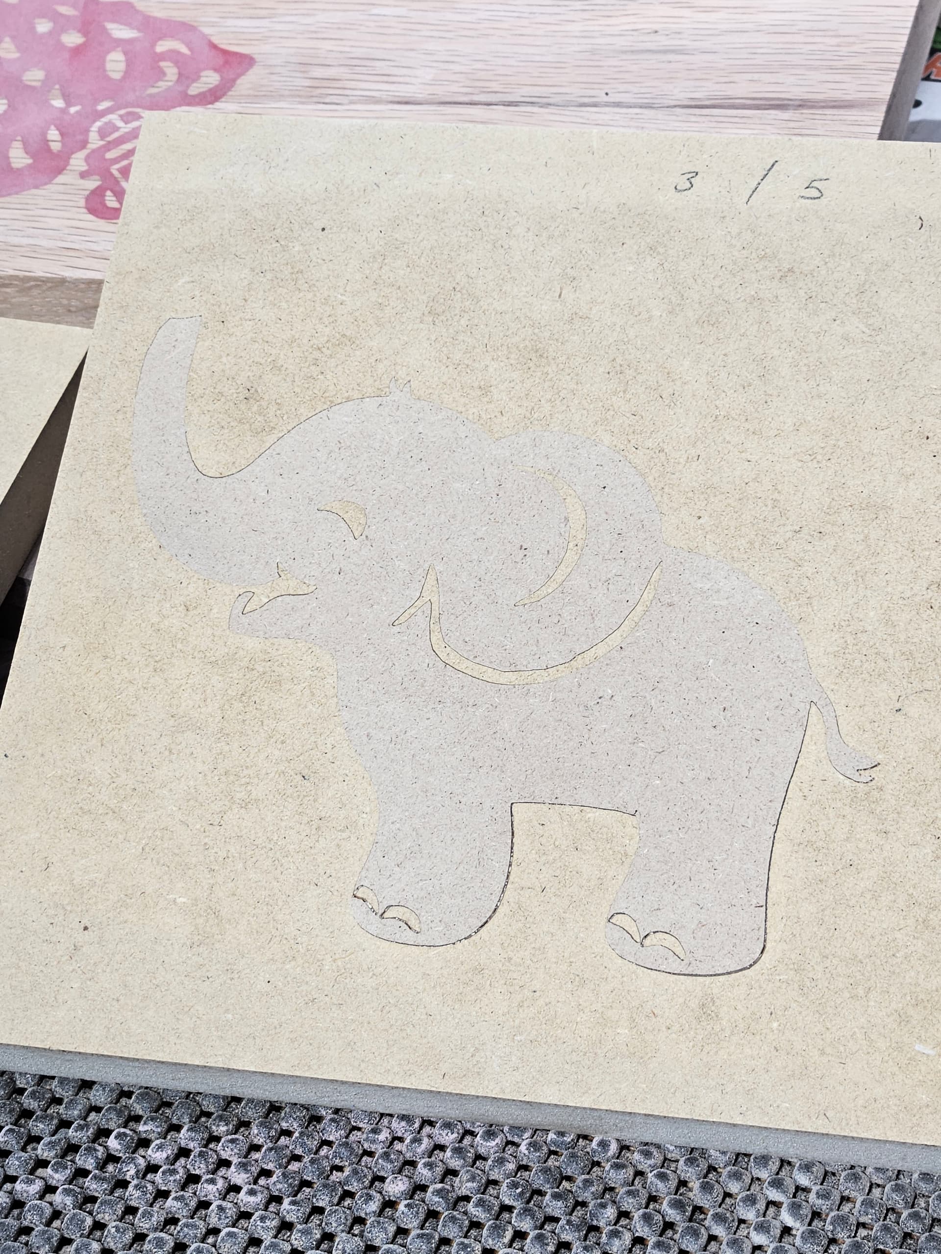
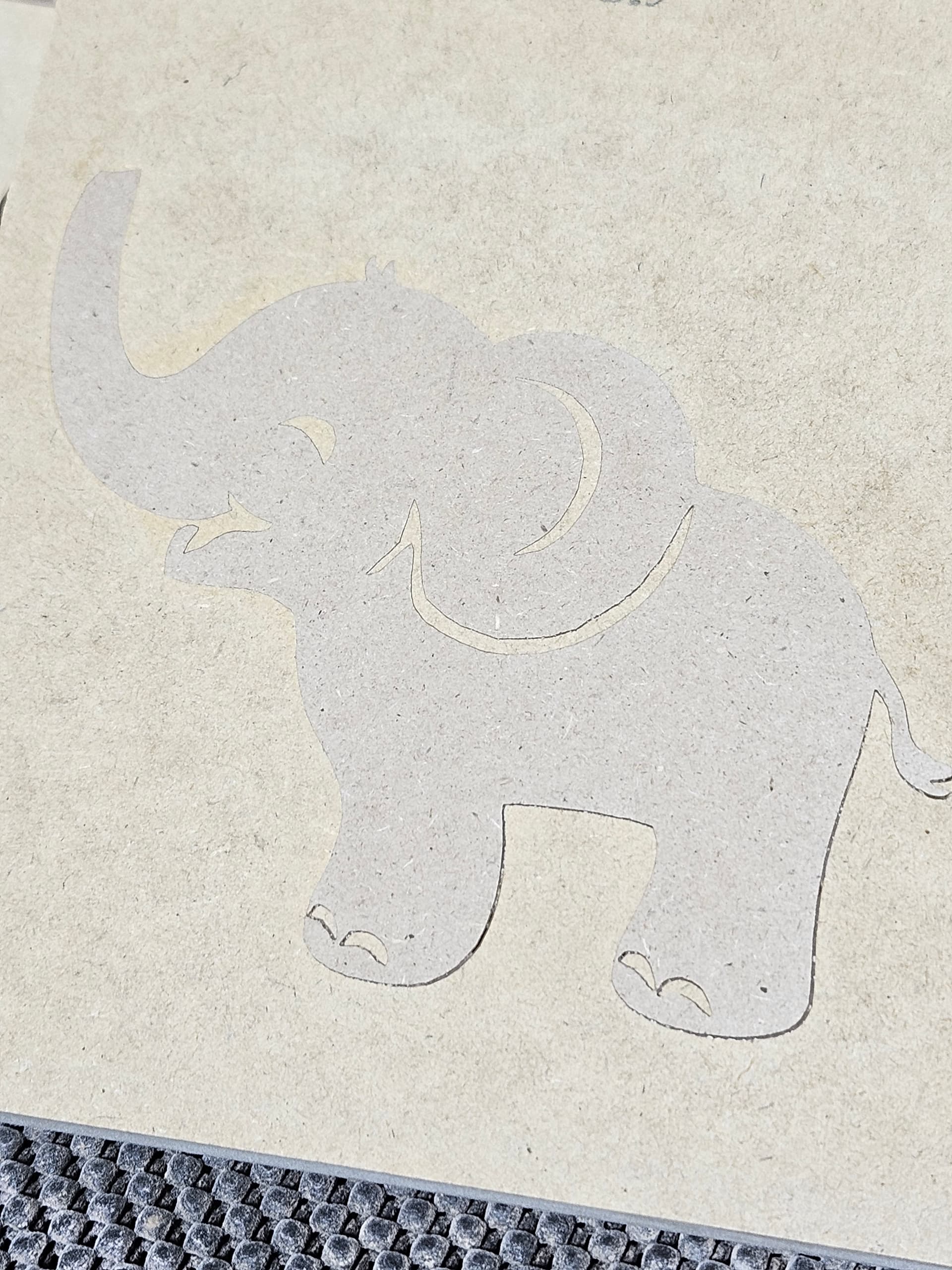
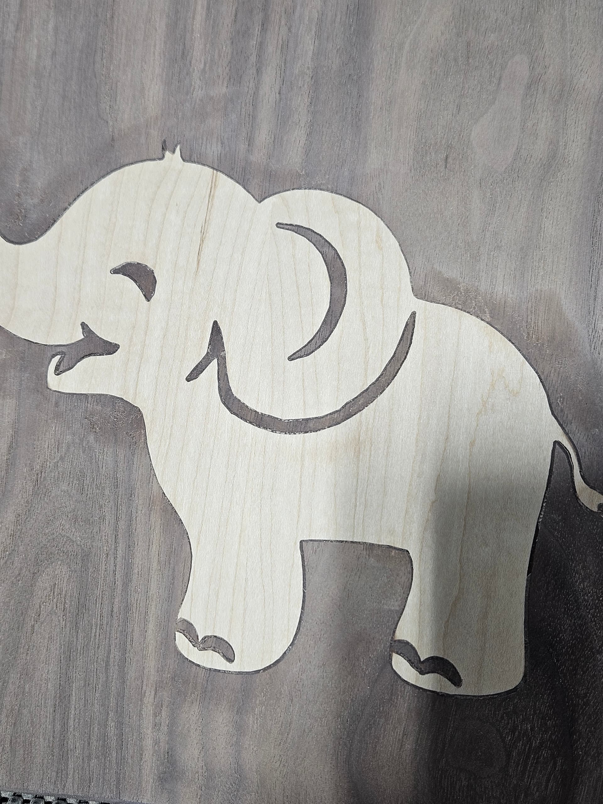
Using a Shapeoko 5.1 with a 60 degree vbit. I think my description was confusing. My gaps are along the edges on the bottom of the design. The photo of the maple and walnut was my first attempt at this design and I am pretty sure that the plug bottomed out, as I got a gap on the edges, all the way around the design. Other pictures are of test cuts I made after that in MDF and still get the gaps around the legs. I have since spent some frustrating time trying to tram the gantry on the machine, but again, I don’t think it was out much to start with. I had also surfaced the wasteboard after assembly and before doing any projects. I’m curious about the possibility that a different bit may help. I can also include the program, but I’m not sure that’s where my problem is. Thank you for the replies so far and the advice. Very helpful.
[grid]
The file won’t do me any good, I don’t have Vectric. But others do.
What about sharing the parameters for the pocket & plug sides?
1 Like
I’m using carbide create (free - that may have to change). Using information off of vidoes from others. The Maple/Walnut was 4.5mm on the plug and 5mm on the pocket. The MDF test pieces are 3mm plug/5mm pocket and 3.5mm plug and 5.5mm pocket. Based on those tests, I landed on the 3mm/mm which is the top picture, cut at full size (the others were smaller versions).
1 Like
Post the file. We can take a look.
Also, what style of clamping are you using?
I use a press.
Baby Elephant.c2d (316 KB)
Since I’m new to this and this is my first real inlay attempt, I haven’t invested in a press yet. Used to pieces of melamine shelf cutoffs (sandwiched the inlay) and then a little over 100lbs of weight on top for 24 hours.
I "adjusted’ the elephant. All I did was remove the Sharp Corners.

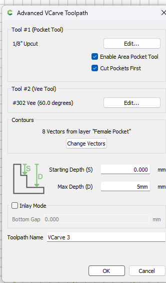
I looked at your file. I see a mistake on the Male plug. The way you input the numbers is based on the Vectric Advanced V-carve toolpath model, which is different than how CC does it.
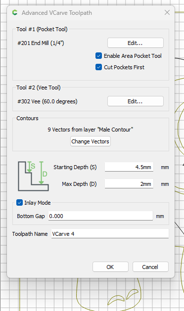
Try these setting;
Male Plug:
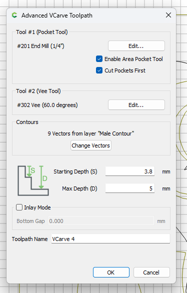
Female Pocket:
Also test these setting with MDF before you work on hardwood.
3 Likes
Thank you for the help. Since I don’t have the pro version, I don’t have the advanced Vcarve. Does it help, or make a difference? I figured if I couldn’t figure out the basic version, I wasn’t ready for the pro version. Did you take out the sharp edges by applying a fillet? Or, did you do it another way? The vectric inlay setup seems weird to me. The terminology seems backwards to me for some reason. In the screenshot you sent for the CC numbers, should I leave a bottom gap for a glue gap? I see you set that as zero. In fact, I see that I don’t have that option in the basic version. Again thank you very much for the help. Trying to make this for my first grandchild’s nursery.
Greg
Yes I don have the advanced vcarve. Sorry, but I don’t see some of the settings that your screen shot includes.
Well. I sound like a complete idiot. Promise I’m not. I just need better typing skills. I DO have the advanced Vcarve is what I meant. It’s just that my screens look different. Thanks.
1 Like
lol… I could read between the lines. Let’s just chalk that up to autocorrect on your phone…lol…
As noted in the announcement for v8:
https://carbide3d.com/blog/create-v8/
There’s now just V-carve (previously Advanced V-carve). If you load an existing file that has a basic V-carve toolpath from V7, it will be converted to the new V-carve without a pocketing toolpath.
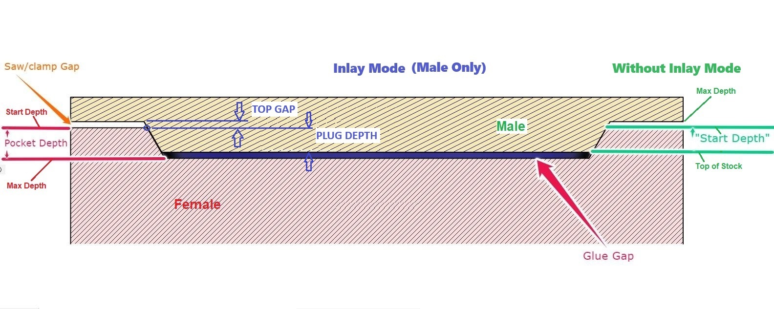
The difference between the old way, Start depth & Max depth, vs the Inlay mode Plug depth & Top Gap, is just putting the numbers in a different place.
The old start depth is now the plug depth. And the old Max depth is now the plug depth plus the top gap.
The one thing you don’t specify is the glue gap. That is the difference between the pocket (female) depth & the plug depth.
The main thing you gain with the new system is it honors the depth per cut, whereas on the old system you had to specify a start depth, and it started there.
If it helps, I use this cheatsheet to make sense of it. Of course you have to imagine the male/top side flipped over on the machine.