Needing some help getting my settings/tooling selection down.
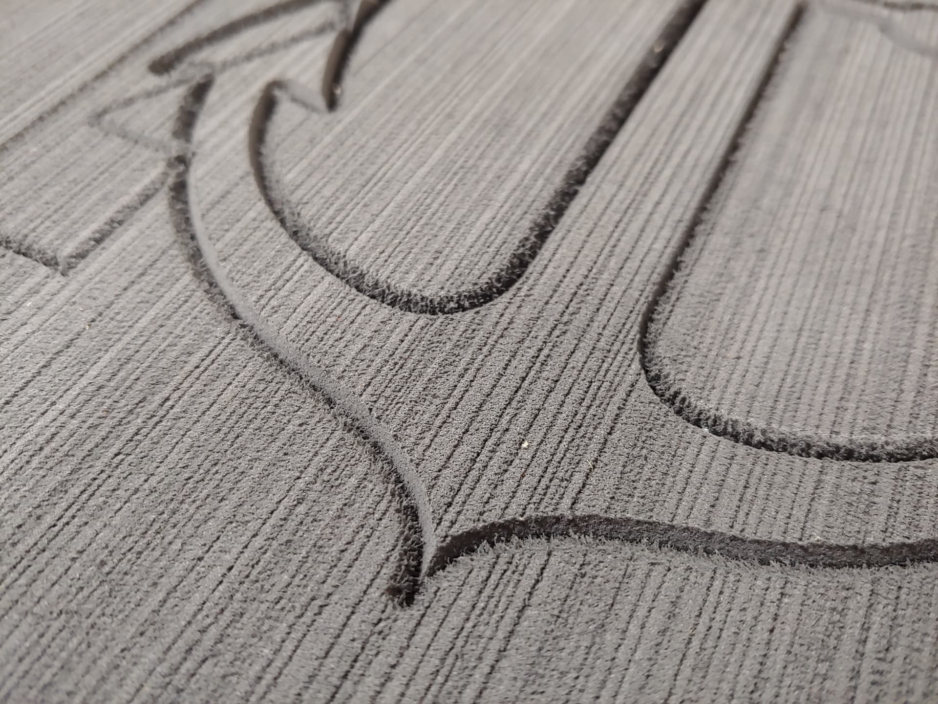
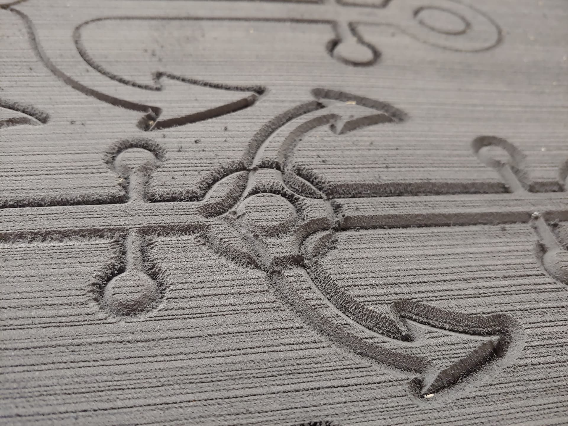
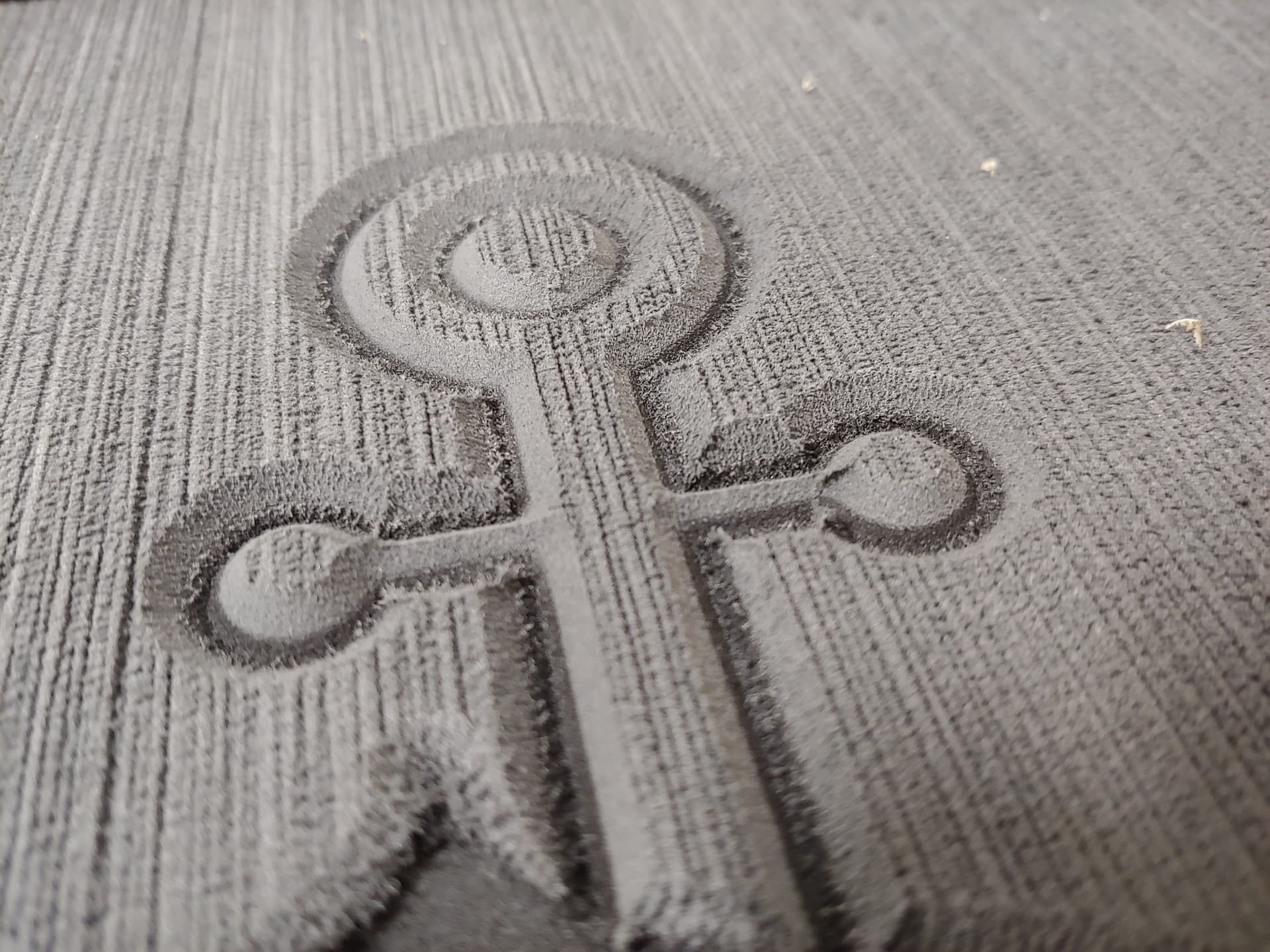
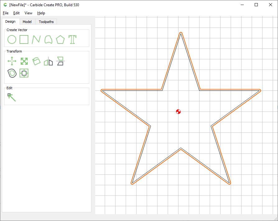
Currently I’m trying to CNC some EVA Foam and I’m just dipping my toes in. I have managed to get good cuts when pocketing and doing general runs but I tried progressing and doing a contour around the edges and it’s giving me some trouble and I can’t understand why. It seems to be cutting fine on one side of the cut but on the other side it doesn’t want to cut fine, and if I pocket before I do the contour it will fray on the one edge it did cut.
Attached is a pic of what I’m talking about, you can see one side of the 60/90VMill will cut about as expected but the other just frays if that’s the proper term for what it’s doing… I would post more pics but it will only let me post 1
I noticed that going from around 17k RPM up to about 28k improved the quality but I already had the machine moving about as slow as it could feed rate wise and 28k is about as fast as it can spin so I don’t know what else to do to keep improving. Any help would be much appreciated!
Here’s some links to the endmills I’m using if anyone has any better recommendations, I’ve heard Burr bits are good for EVA Foam but I haven’t purchased one yet, should I?
I know next to nothing about cutting EVA foam, but I am under the impression that there are specialized cutters for foam that may help (and probably be incredibly expensive too)
Winston has a good video on cutting foam, but I have no idea how far EVA foam is from those kinds of foam he is using in the video:
Why would you try and go as slow as possible ? The experience I have with plastics (albeit much, much harder ones) it that one never feeds quite fast enough to keep them happy. At least I would try running a that contour job FAST, reducing the depth if needed (but it looks shallow), see if that improves anything.
The only other idea I would have is running a second pass on the same contour but running in the other direction (toggle between climb and conventional, if your CAM tool supports that option). Hopefully that should clean-up the “other” side.
Yes I saw that video but he doesn’t do any contouring and I already have the regular functions operating reasonably well. EVA Foam is quite a bit more dense than the foam he is using and the stuff I have is only 3/16 of an inch thick and I will never be cutting completely through, 60% at max just to get the other color to pop through.
The wiki has great information but nothing about running contours on foam that I could tell.
I appreciate the Datron link I hadn’t seen that yet but I will look into it for sure.
The only reason I was running the machine as slow as I could is because I also ran it as fast as I could but the results were worse, so by giving it more time to cut but keeping the RPM up I’d imagine that would just give it a better chance at actually cutting no? I will try running at a half depth pass and full speeds as I haven’t tried that, only full cut depth at full speed and see if that changes anything but I feel like it wont.
Any idea on why it cuts fine on one side but not the other though? That’s what makes no sense to me, it will cut fine, just on one side, the side I don’t need to look good haha. Guess I’ll have to pull the trigger and just buy some more endmills to test out.
well I don’t know about EVA foam, but generally speaking, if you are running at very high RPM and very low feedrate, you are effectively reducing the chipload (if “chip” makes any sense in foam…) to something very, very small, small enough that it’s likely that the cutter will rub/melt the surface rather than cut it (in wood, doing that would result is burning the wood and dulling the cutter). That said, your “inner” edges look fine, so maybe ignore that.
It being so consistent tells me it the cutting direction (climb vs conventional). What software are you using?
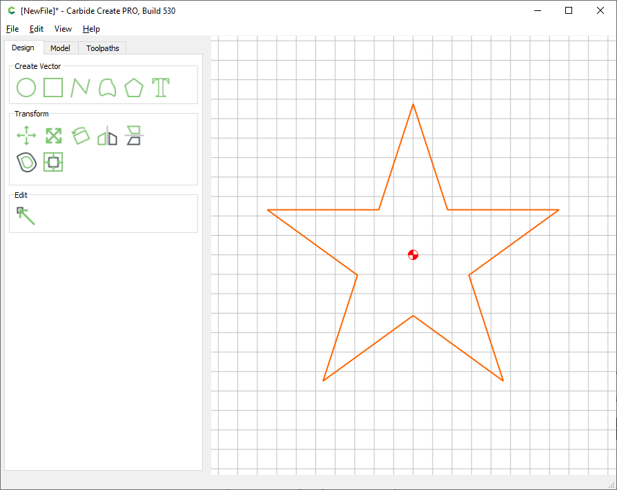
I was thinking something about the cutting direction but I didn’t see anything in the software to change that, maybe I’m just blind. I do have glasses so…
I am just using the free Carbide software, should I look into something a bit more professional?
I ran back over to my CNC and ran a few more tests, one at max speed and one at minimum speed and slowed down even more within the carbide motion software and it looks like faster just means more fray. I think the solution could be what you were talking about, the cutting direction, or possibly the fact I’m using a grooving bit…
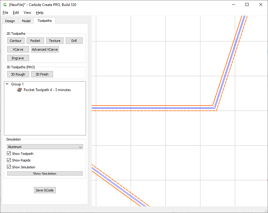
Say you plan on using a 1/8" endmill (for the sake of the example). Create an offset shape in the outside direction, by an offset that is slightly more than the cutter diameter, e.g. 0.15"
You will find that while cutting that pocket, the first (outer) pass is in the same direction as if you did a contour profile, but the second (inner) pass that will come an touch the original shape profile, is in the other direction, which is what you want here.
You could try that, maybe on a simple circle/square test shape, for the sake of verifying whether the “cutting direction” hypothesis is the correct one?
Thanks again Julien I really appreciate the insight on this.
I will give that a go later when I can find the time to hop on the CNC and see if it’s something to do with the cutting direction. Is their a way where I can have it pocket and go from the inside of the outer object to the outside of the inner object but leave a strip in the middle so I can look at both cuts for both passes?
Is their any other good freeware out there I could use to run some different tests that you know of and you’d recommend by chance? I like Carbide Create but I wouldn’t mind messing with some other software to learn a bit more and figure out if Carbide’s is best for me or not.
Not using a single pocket toolpath. With a combination of multiple pockets and contours maybe, but it’s probably too much of a headache to be doing in CC.
Freeware, I honestly couldn’t tell you…other folks can comment maybe.
Pseudo-free, there is Fusion360 which is fantastic (awesome CAM features accessible to hobbyists), but has a steep learning curve, uses the junkie business model (it’s free until you’re hooked and later you’ll pay big bucks to continue using it), and is honestly overkill and a bit awkward for pure 2D projects. Not something you would want to learn just for a few tests cuts, it’s more of a long term investment.
Paid software, I use VCarve Desktop, which is excellent albeit somewhat pricy. There is a trial version but as far as I remember it only allows one to generate G-code for predefined project samples, so while it is great to get a feel of the software interface, it will be useless for your specific tests.
There is also EstlCam which is probably the most affordable paid CAM software, and it does have control of cutting direction and a whole lot of other nice CAM features. It’s a little bit of a UFO in the CNC market (developed by a single German guy as far as I can tell), but the value for $59 is admittedly great.
The other popular option for paid software is CarveCo, for the folks willing to do month-to-month payments.
For free/opensource the big option is FreeCAD for folks who can put in the effort to install, learn, and use it, or, there’s SolveSpace (which would require separate 3D CAM such as MeshCAM). For programmers there are tools such as OpenSCAD.
note that a pocket is also good to get a better cut vs slotting in general… the final cut to the shape is much thinner than “full endmill” which tends to get you better cut quality