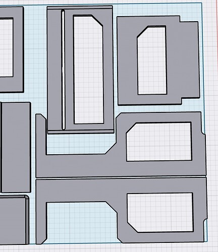
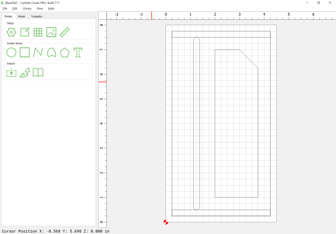
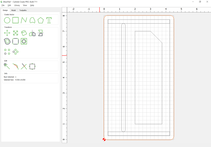
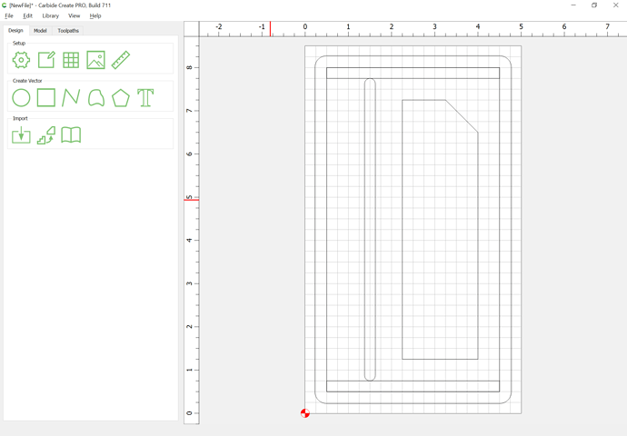
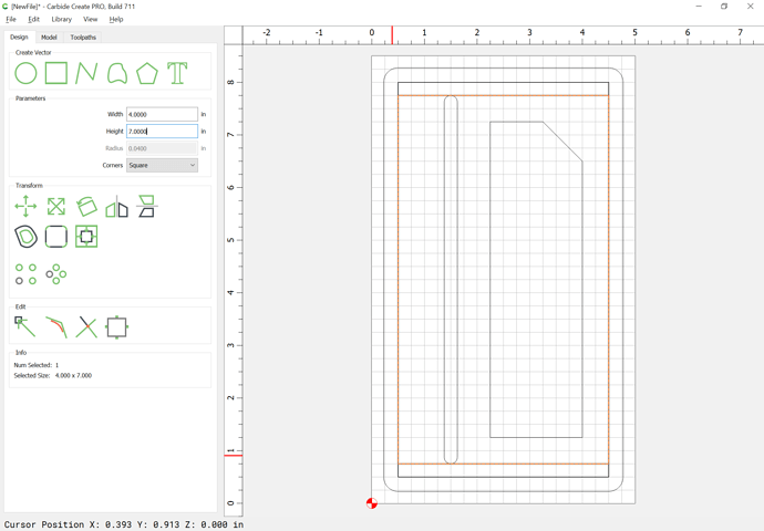
Okay, here’s a rough re-drawing of the geometry of one part to cut out a mockup of one part:
The only geometry which needs to be modified is the rabbets at the end, and the outline, since one doesn’t want to cut a slot as deep as the part — you can combine the twain:
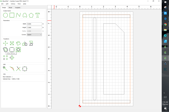
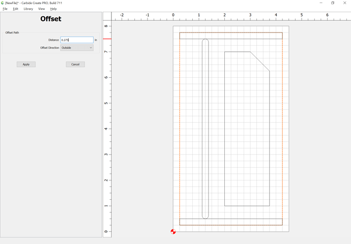
First select the part outline and offset by endmill diameter plus 10%:
(this will be a bit clearer on a larger piece of stock):
Then it’s time for toolpaths.
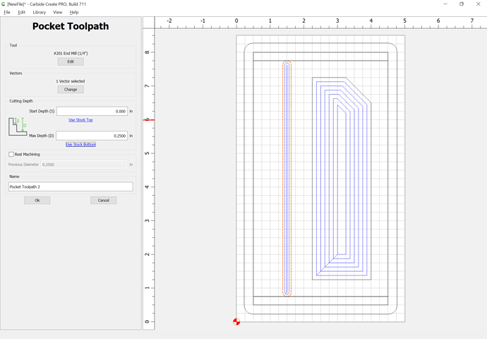
You’ll want to cut out the interior first (there are a couple of ways this could be done, this is just one approach:
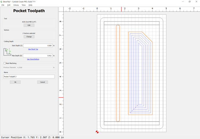
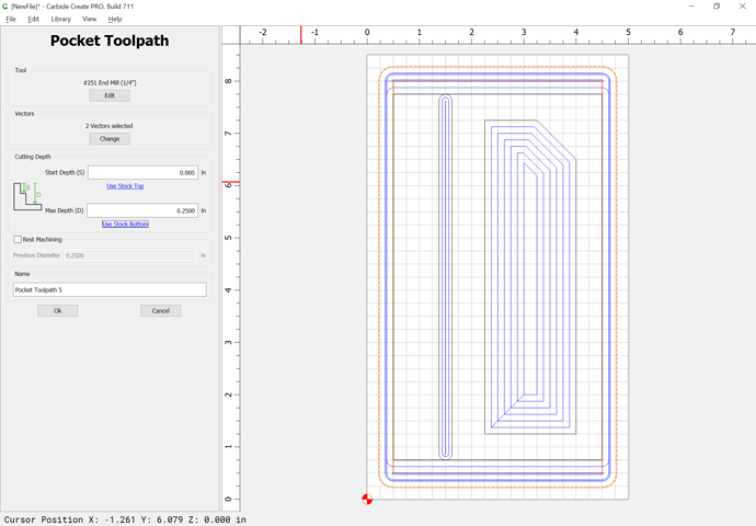
Select the inner geometry and assign a pocket toolpath to cut them out (if the areas are large enough to merit saving, go back and do an offset to the inside as above and cut as a pocket)
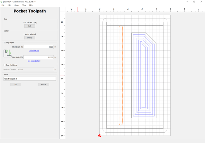
If a region is too narrow to be cut out, use a smaller tool or redraw the geometry if you wish to cut as a slot:
If need be, adjust cutting depth:
Then, select the central/raised/non-rabbeted portion of the drawing:
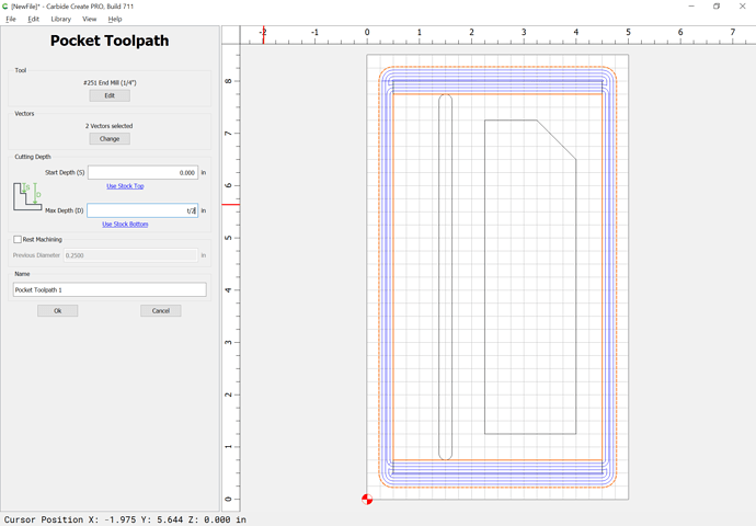
and select the offset from above and assign a toolpath to half the stock thickness:
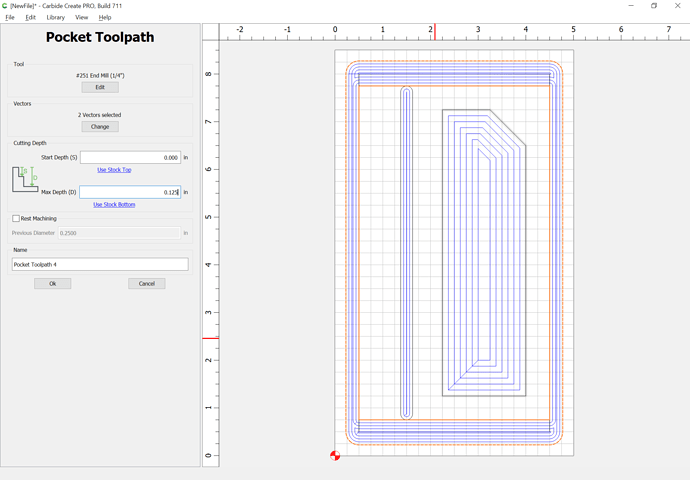
Then select the part outline and the stock thickness and assign a pocket toolpath down to either tab height or the penultimate pass or all the way through, depending on whether tabs are needed or how the part will be held in place:
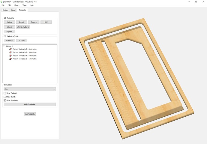
and it previews as:
Here’s the file in v6 format to examine:
partmockup.c2d (109.3 KB)
MeshCAM could do the same sort of thing from a DXF and might be easier.
