I’m super intrigued by using the machine, a Nomad 883 Pro in my case, to control external devices like my air blast setup. There are seemingly a few ways to skin the cat on this; trigger the switch/relay/transistor on PWM for the spindle or use the A3 pin breakout which is triggered by M8/M9 codes. M8/M9 being highly preferred as my application would really like to be decoupled from spindle but they say you can’t have it all in life…
Has anyone went down either of these roads on the Nomad or Shapeoko? Any lessons learned? My understanding is Carbide Motion ignores M8/M9 so I’d need to use a 3rd party g-code sender, which is too bad.
If no one has tried this level of mischief yet, I am happy to give it the good ole’ college try and my life choices can serve as a warning for all of you.
One day with no responses is all the impetus I needed to be set sail to the land of machine mod hooliganism. An incredibly kind member of the Carbide3D staff pointed out that version 4.0.428 of Carbide Motion contains M8/M9 functionality so over the next few nights and weekends, I’ll work on getting my air blast rigged up to a relay triggered by the machine and document it for anyone who’d like to do the same thing!
I have not done it myself but I think people here have reported using GCode to trigger their ancillary devices. Have you done a search of the forum to find out. Because someone has not replied yet does not mean it wasn’t done. You may learn from their experience before you put your effort into the project. I’m a firm believer in standing on someone else shoulders to reach the top. Of course this may also sway you in a certain direction and not consider other possible options.
The main issue would be there is no pins to facilitate this.
That said you can trigger a low level relay off the PWM/M3 output which enables the spindle control. I.e. when spindle is enabled a low level air relay is opened and air is free flowing…
There is nothing official here but I had this setup.
I use the “flood coolant” (M8/M9) for controlling an aux. power supply used only for a Laser. Works great (connected to an SCR which controls power to the aux PSU) . As has been noted, you can’t do this with CM, but with another sender you can.
It’s non-trivial with stock carbide motion board to get this wired up because there isn’t a pin brought out for it. Possible, but fussy. If you don’t consider yourself an expert at solder rework I wouldn’t suggest it.
It’s a lot easier with a different controller board. The process of setting one up isn’t terrible, and if you’re getting to the point you want to manage different external devices, you can probably handle it without a lot of effort, it mostly involves removing the existing connectors from the steppers and limit switches.
Awesome.tech has a new board coming out (they proto everything on a nomad) that has its own display and SD card slot. Their “supergerbil” boards are out of stock, but work well. I recently pushed some changes back to their firmware to improve some compatibility issues. I’ve been using one of these for about a year, but I recently made some silly mistakes (100% my fault) that has relegated it to “the healing bench.” It’s somewhat more difficult to set up than the TR board below.
Another option is the Toms Robotics (TR) board, which I think is easier to set up. Has sockets for internal drivers (available in one of the bundles) or external. Cheaper than the awesome.tech board, and uses a “blue pill” arm cpu that’s easily replaced if you damage it. The F13 board is very much like the standard grbl implementations, but runs on ARM, and has more memory - seems to run a lot smoother, and has one aux. digital output (beyond flood, mist, spindle enable pins). The F14 and F46 boards have a number of additional digital outputs for controlling many external devices. https://shop.tomsrobotics.com/product/f13-bundles/
You can also use an arduino/328 board with a GRBL shield. My first foray from the carbide board was this route. The quality of the shield boards is pretty hit or miss, and doesn’t gain much over the carbide board besides getting easy access to all the pins. Be sure to get a shield that’s compatible with grbl 1.1 (there was a pin definition change).
I use it for my vacuum but there is no reason you couldnt use for any other device/appliance
I use it in conjunction with the PWM/M3 as @Luke mentioned above , so my spindle automatically turns on when the job starts (along with the vacuum via the ivac) and then everything shuts off automagically at the end of the job so I dont have to keep checking on it every time it gets close to finishing.
If all you’re looking for is turning on something at the same time as a spindle, yes. That’s not what OP was asking about though: “M8/M9 being highly preferred as my application would really like to be decoupled from spindle” - The OP refers to air blast as well, so not sure if it’s an arbitrary 120v device, or a relay/solenoid setup.
No worries guys! For me, I’ve always been the type of adventurous modification seeking user. I’ve got all the materials on hand and a seemingly reasonable/straightforward plan to make this work. I’m researching a few solderless ways to make this work as well and could consider making this a plug and play external module for these machines. Hopeful I will be able to make serious progress on this tomorrow!
And yes, definitely want to use m-code to trigger output that way I can use the spindle triggered output to control something else!
It’s alive!!! Definitely was not entry level soldering and getting it to post out from Fusion 360 required minor post processor modification (scary-ish) but I am able to command a 5VDC relay on and off from M8/M9 commands in program running on the machine! Really excited for all the possibilities this opens up.
Will throw some photo documentation and stuff up tomorrow, need to get some sleep.
Please note this is in the ‘unsupported’ forum and this soldering job would be perilous for beginners but very achievable if you have done hand placed PCBs with small components. Having the right soldering iron for this will make all the difference. As background, this solution decouples the output from the spindle. The A3 connection toggles to 5V when M8 is commanded in your g-code and stays on until M9 appears in your code. I intend to run an air blast custom cycle between operations; M8 will turn on a relay, I will have code to move carriage around to pockets or slots that need blasting and then M9 will shut off air blast and the machine can go about it’s business chomping metal. Could I just run my air pump the whole time the machine is running? Yes. But it’s 2020, I should be able to command an external device with my machine.
I plan to do this!
Undecided
Too risky
0voters
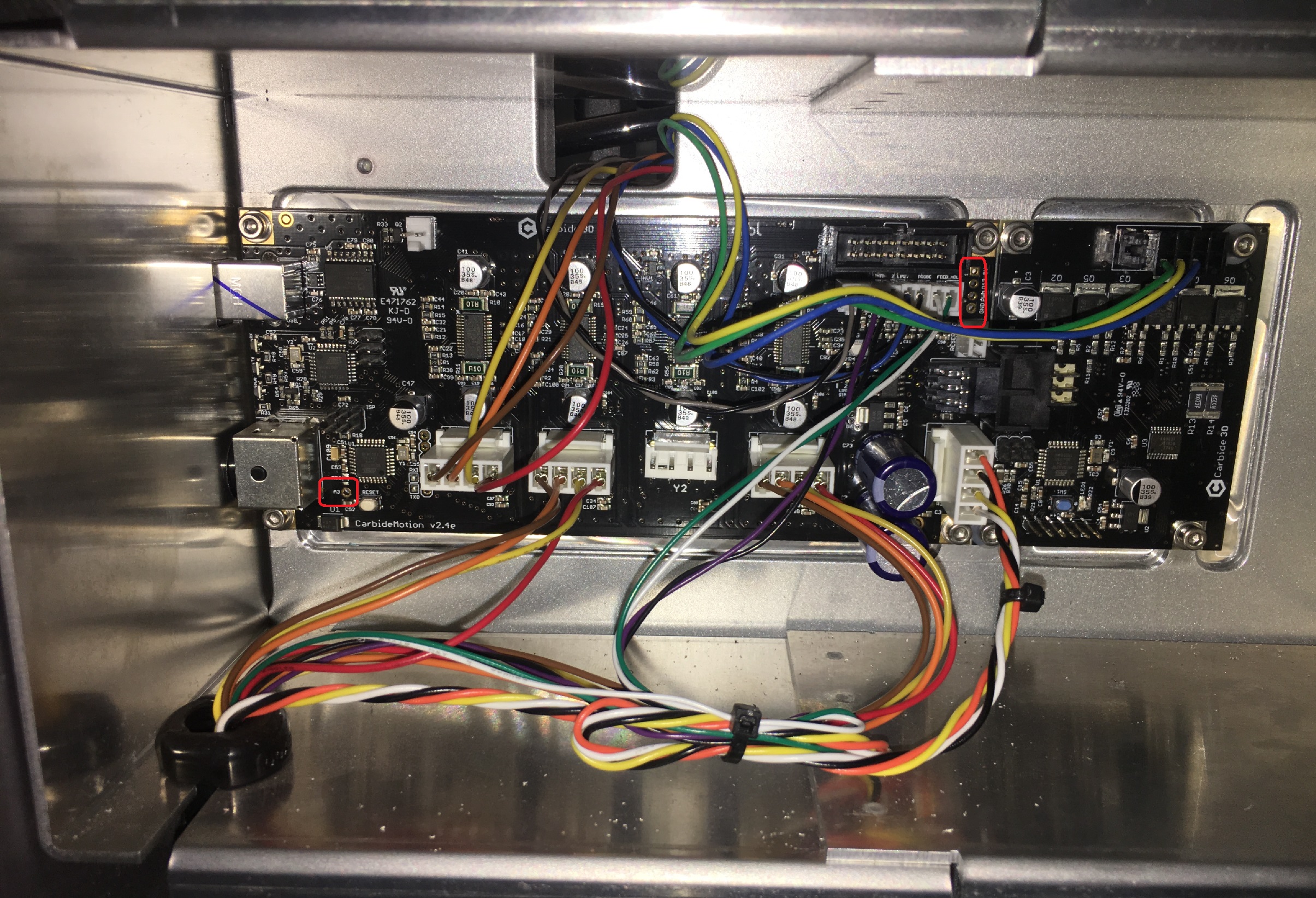
Unplug/disconnect machine from power and USB connections
Remove back cover of the machine. Note, some of the lower fasteners do not and should not be removed as they hold the y-axis stepper and y-axis rails in place. Bonus points if, after removing the cover, you put the fasteners back in the threaded holes so you don’t lose them.
Remove the 4x threaded fasteners from the control board and the 4x threaded fasteners on the spindle control board. I was able to do this modification with all the stepper and limit switch wires still plugged in but it significantly raised the difficulty. Definitely label the connections if you decide to remove them to make access to soldering pins easier.
Both boards have an adhesive backing to the machine; a combination of lifting, peeling and wiggling will get them removed from the aluminum frame but it will take more force than you might expect. I removed the spindle control board first, since this allowed me to disconnect it from the control board Molex connector and get it out of the way. Make sure the adhesive on the boards remain clean throughout this process.
With access to the back of the board, header pins get soldered in on the positions in the red boxes. Be careful. If your solder isn’t flowing to the pin and copper on the board within 1-2 seconds, you probably don’t have the right iron for this and should abort mission.
With pins soldered in place, check there is not low resistance between any of the header pins. You should see several mega ohms between everything. If you see a few ohms, carefully examine between those pins for an inadvertent solder bridge and repair it. Definitely do not power on the machine without doing this check.
Reinstall boards making sure the aluminum surface the adhesive tape interfaces with has remained clean. The boards should stay in place just from the tape, making fastener installation easy.
I ran test leads from the A3 pin and the 5V and GND pins to a relay and was able to toggle it on and off via M8 and M9 commands in MDI mode of Carbide Motion on versions newer than 4.0.428. The following code can be run to toggle the relay every 1 second for test purposes:
Getting this to post directly from Fusion 360 custom cycle was tricky and involved modifying the post processor. Any time you are considering modifying a perfectly good post processor, you need to sit down and think carefully about your life choices . Afterwards, pending you haven’t come to your senses, the modification is documented by Autodesk here
Next step is design sweet NEMA 5-15 to IEC enclosure/PCB with a relay that I can interface to the machine with some standard automation cables so this entire thing is less of a science project.
you forgot one line in the poll, “I had no idea I could leverage M8/M9, I had no idea I wanted to do it before this post, and I will probably regret going down yet another rabbit hole, but man do I want to try this just for sports”. I would definitely check that line
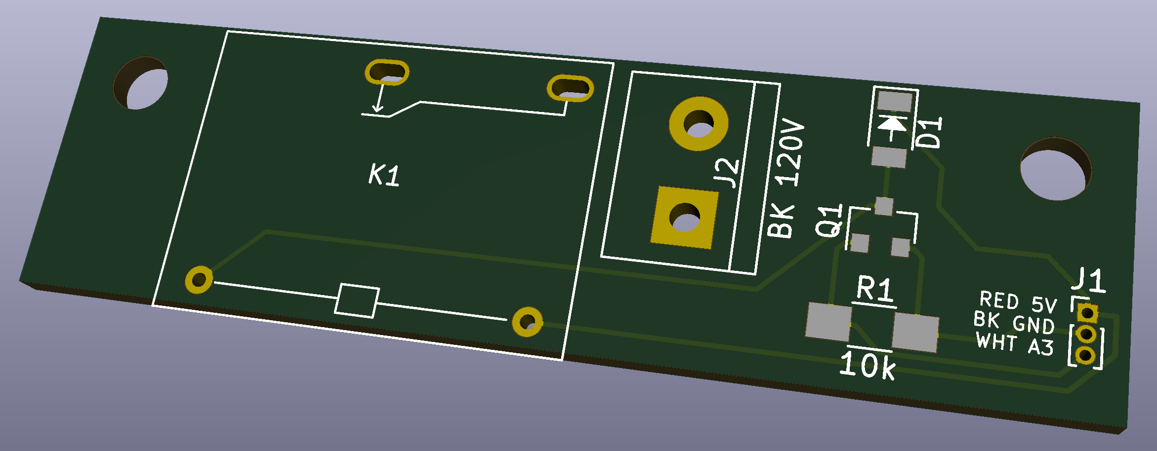
The breadboard test mule is way too sketchy to use in real life so have put time into making this a real automation grade accessory for the machine. Designs for the PCB + enclosure mechanical are wrapping up; it’ll be pretty tightly packaged. Although it’s unlikely to ever necessary, I sized everything to actually run 15 amp continuous accessory so I will never have to think about if the box will handle it. (As a rule, I want the wires in the walls of my house to catch fire before I’d risk damaging my Nomad.) This drove up connector, component and trace sizes so had to iterate 4-5 times to keep everything in small enough enclosure I could do the cutouts on the Nomad.
For anyone looking to go further down the maker rabbit hole, I did the schematic and board layout in KiCad and have always used OSH Park for my board spins. Fusion 360 was used for the 3d designs and CAM.
The board itself is 2.125" long by .625" wide. I’ll get it done in 2oz. copper since it will keep 15A traces to managable size. Need to debate thermal reliefs on the pads still.
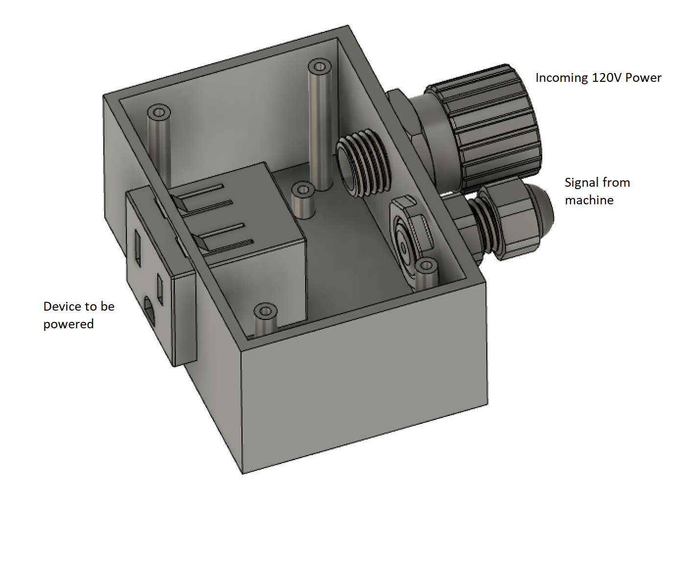
In real life, obviously this will have a screw on lid. Getting all those mechanical accessories to not interfere with the board was an exciting challenge. The incoming power cord grip will have a standard NEMA 15-5P plug and the signal cord grip will have small cable running to the machines A3, 5V and GND pins to control the relay. Device you want to control; air blast, air pump, vacuum system, beer fridge, power strip powering all of those things, etc, would just plug into the box. Not shown because I got lazy, box will also be flanged on the bottom so I can just screw it down to my workbench.
Should have prototype up and running in 2-3 weeks!
I’ll double check design rule spacing on traces later but those routes are just 5V logic stuff so wasn’t really worried about creepage. I have no good reason why I didn’t go solid state relay, aside from just heritage running relays like this on other projects. Probably need to get with more modern times… I’ll trade solid state in the design later tonight.
Definitely agree getting a ready made module would be easier and easier. I haven’t designed a circuit board in 3 years so wanted to have a short putt type project to get my feet wet again. We will see how it turns out…
It is the path from the 120VAC to the 5V that is the worry. Without dimensions and full layout for both sides of the board, I can’t judge for sure, but it appears to be less than 5mm from high V to the low V on the shown side.
As @enl_public points out, the isolation could be better. In addition to a little space, an isolation slot is cheap, and a significant improvement over just trace spacing.
 so I dont have to keep checking on it every time it gets close to finishing.