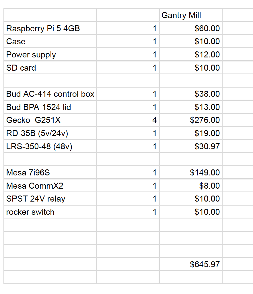
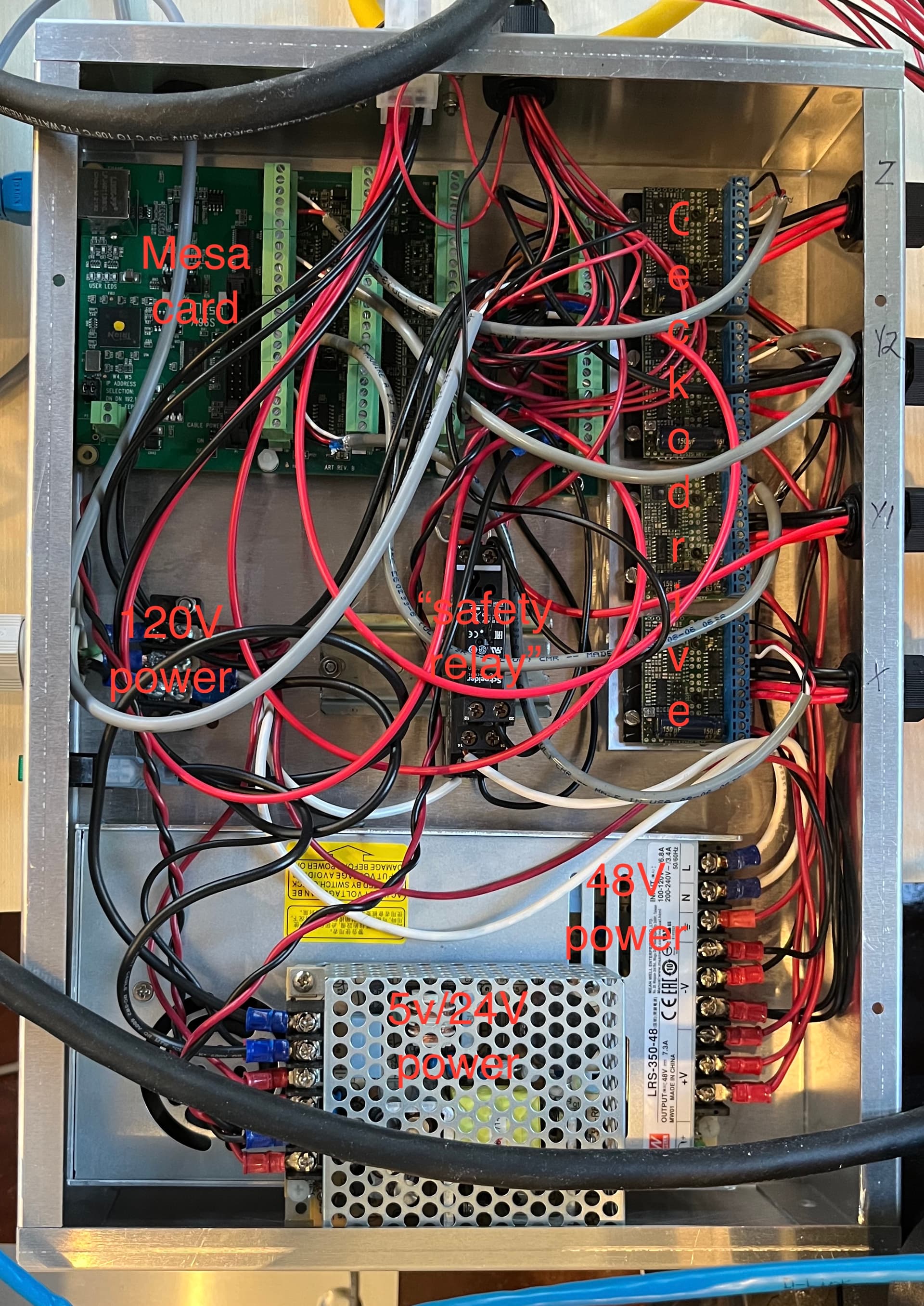
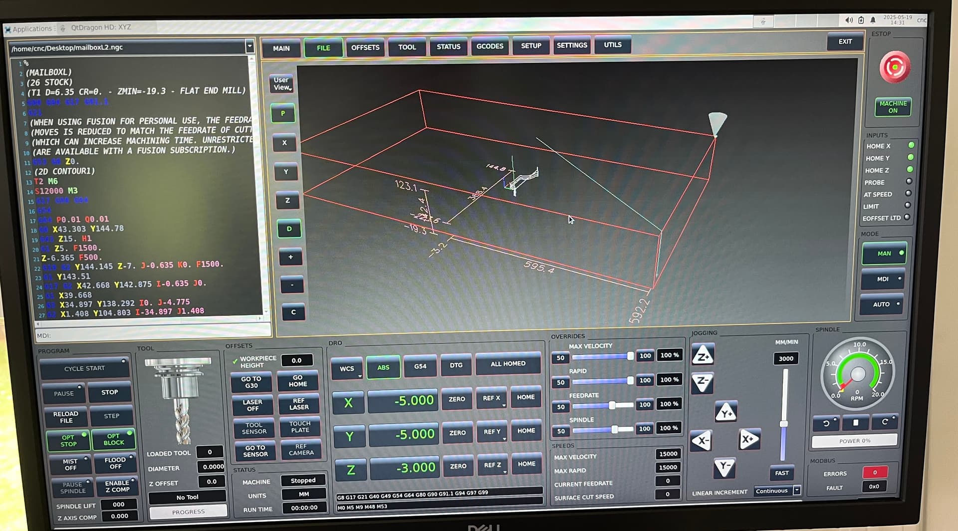
As an introduction, LinuxCNC (linuxcnc.org) is a free, open source software used to control CNC machines, robots, etc. It is fairly agnostic to hardware, so it is not a “system” and it’s not plug and play. My system uses LinuxCNC running on a Raspberry Pi 5, a Mesa Electronics ethernet interface board and Geckodrive stepper drives. There are several choices of UI, but the nature of LinuxCNC is that everything is customizable. I use the “QTDragon” interface on my system.
The stock SO5 controller has three connectors: an 18-pin for steppers and LED, a 22-pin for home switches and bitsetter and a 6-pin for power/estop/pause. My goal was to use the factory wiring as much as possible (i.e. just replace the controller).
That’s really awesome! Couple questions… Did you consider adding a 5th axis/rotary? Looks like that setup would support it with just an additional G251X?
How long have you been using it since you converted? What makes you believe it is “easier to use?” Carbide Motion is very easy to use, it just doesn’t allow a lot of customization…
I’m considering the merits of a conversion like this, but would probably be adding more powerful steppers and a larger spindle if I did it. I feel the base hardware is very good, but I definitely bump into some of the limitations… What are your plans? Stopping here, or more in store?
The Mesa card selected supports up to 5 axes. Easy to add a rotary.
I’ve been using it for over a year, but I’ve used LinuxCNC for over 10 years on a CNC mill. It’s rock solid and used by many to run production machines.
Easier to use: Jogging, homing, work coordinates, start / stop spindle all from the main interface. G-code scrolls as its running. Visible indication of tool position, work envelope (soft limits) and toolpaths. From cold startup, I’m ready to run the machine in less than 60 seconds, including homing.
The basic hardware of SO5 is good. With ~44 volts on the stepper drives, X and Y rapids are 600 IPM(15000mm/min). Motors run just a little warmer than stock (which has 24v for steppers). I just spent a little time programming automatic tool measurement and it works great. I changed all the home switches to M12 (industry standard) and eliminated some molexes in the drag chain. At some point, I may add a true spindle with VFD.
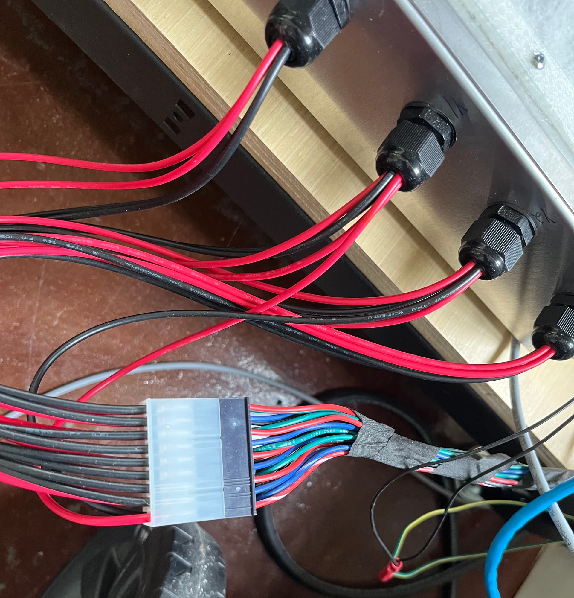
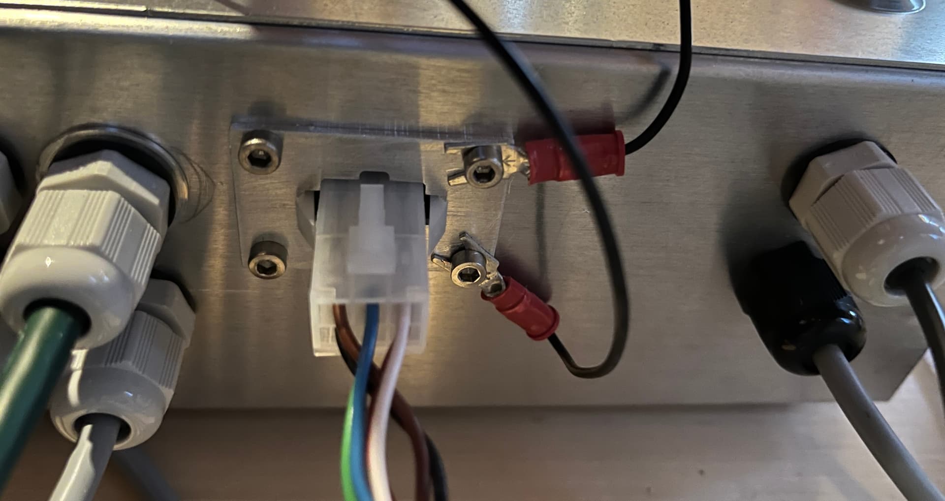
I used precrimped 18" wires available from Newark/Allied/Digikey to make pigtailed connectors for the stepper and home switch connectors. Then ran the wires through cord grips. I used a panel-mount connector on the box for the power/estop connector since it has a long cable. Had to make a little machined plate to fit the locking tabs.
Do you have the pinout for the warthog controller motor and switch connectors?
Did you have to trace the wires 1 by 1 to determine which motor/switch wire went where?
This is the IO connector pinout measured from the controller side. On my harness, some pins were unpopulated or broken. GND is the minus side of the 24V supply. I seem to recall the probe comes back as 5V from the “C” logo board on front. I redid my probe with a proximity sensor.
This is the stepper connector. I didn’t pay attention to motor direction since I disconnected motors and verified before running new controller(important that y1/y2 run in the same direction). Its usually easy to change motor direction in software. Motors reading in the 1.6 ohm range per phase (i.e. + to -).