Does anyone know if Kevin Barnett ever published a file for the corner bracket that he used in the Flip Machining video?
I am working on project where I will be carving out a design on one side of a medallion, then I need to flip it so that I can carve out a pocket for a small magnet on the back of it.
I have tried the flip machine technique with the flip frame as shown in the video but it will be much easier if I have the corner bracket to reference the piece when I flip it.
I also tried to cut out the corner bracket L clamp from Meyers woodshop but the cut out for the bitsetter v2 is way too small so it will not work without some manipulation of the file.
I saw this suggestion from Will Adams in a previous post for the same topic:
“There are multiple ways to do this — my preference is to design the project w/ Center Left origin w/ top/bottom at the top/bottom half of the stock, then do the top half first using the origin as lower left, then do a flip rotating the bottom left corner to become the top left corner and using top-left as the origin — if you could post a file we can walk through this with you.”
Perhaps he can elaborate on this process with a sample file for reference.
This was faster to just create rather than try to find Kevin’s. 14 x 14", and the holes are spaced 100mm for your T slots. Adding dowel holes so you can get it back in the same spot might be a nice enhancement. Cut the dowel holes through the bracket & into the spoilboard.
Another way to do this is to flip the job around an axis that runs from front-left to back-right at a 45° angle.
This keeps the “J-Corner” in the lower left for both sides. No resetting zeroes. A little bit more work in setup, but not much. In the flip side setup, mirror the geometry horizontally, then rotate 90°, so the ‘front’ of your part is now on the left side.
If height/thickness is critical, you can even do the top half with the Z zero at the bottom, and the bottom half with the Z zero on the top, or vice-versa. Now your zero is the same point on the physical job in both setups.
Rather than try to get through cuts to line up perfectly, I would cut all the center detail on the first (Top) side, do my flip, cut the center details on the back/bottom side, then cut out the profile full depth (with tabs if necessary) from one setup.
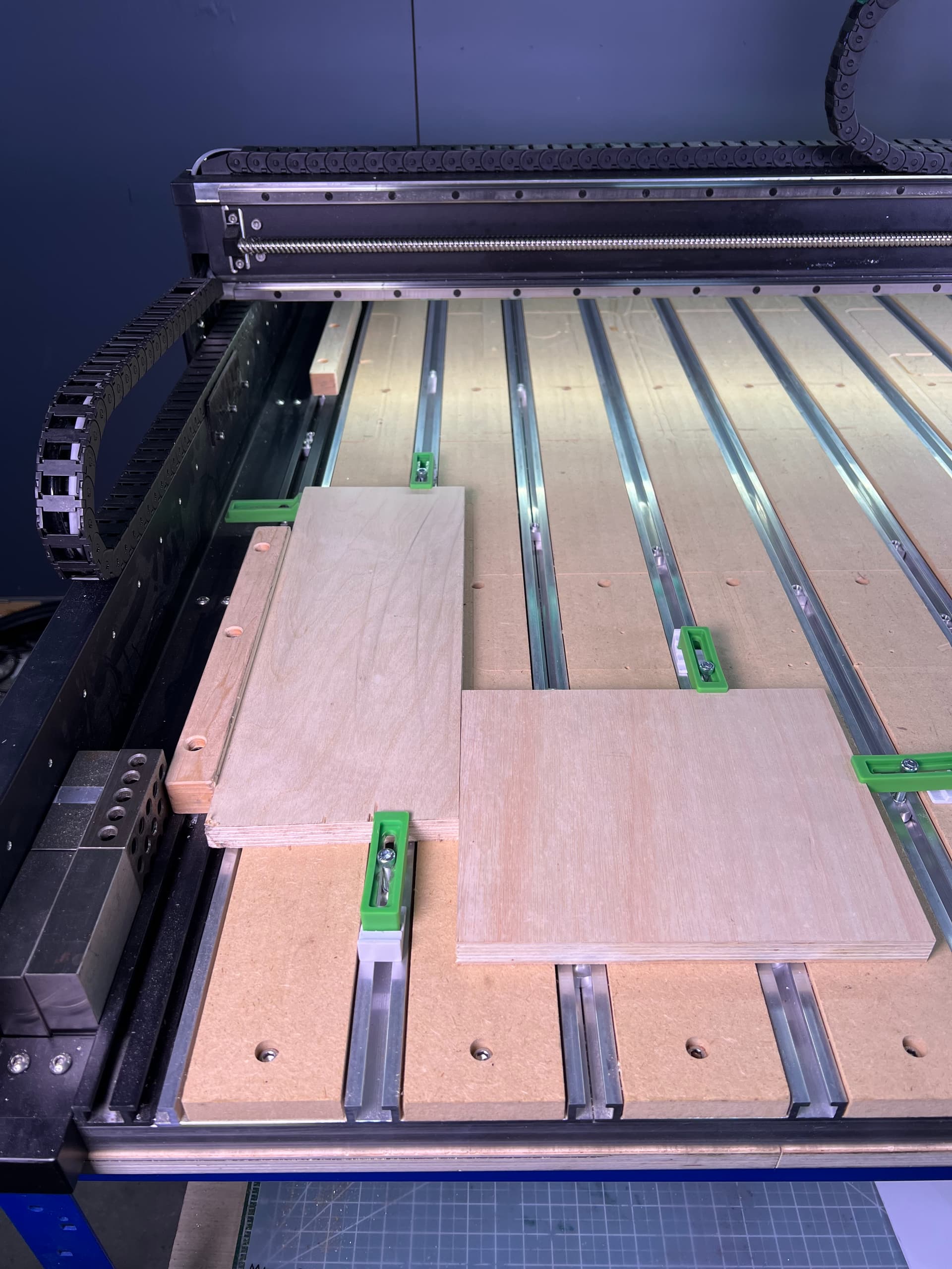
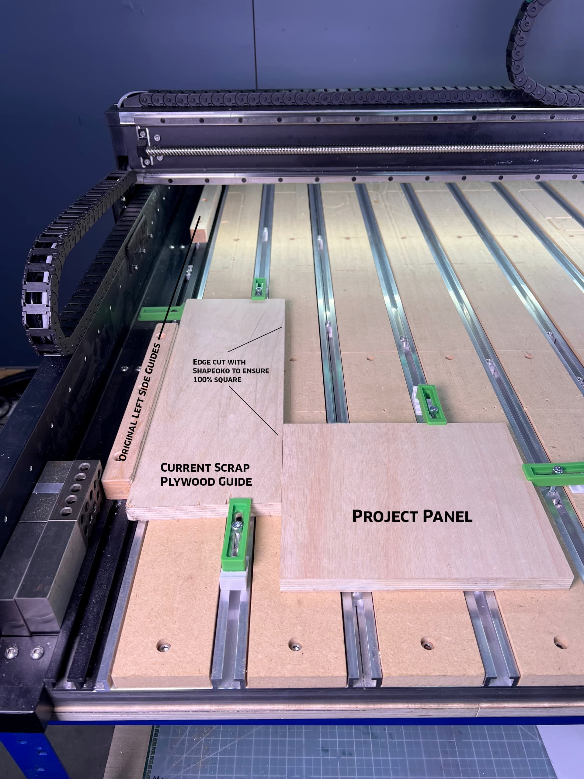
My orginal left side guides have been cut back a few too many times, so I cut a piece of plywood as a guide. This setup works for small to medium projects. When I go for the next large project I’ll have to replace my original guides.
The dogbone cutout is for the corner of the part. The bitzero would fit on the part corner.
For shorter stock where the bitzero won’t fit, you could use a taller piece to set XY zero, then reset Z to your actual stock.