Brand new user. In past 40 years I have always cut by hand using my routers. Doing artwork from images or now jpg, tracing onto wood and then routing them freehand. Before I buy a CNC I figured i’d use the software first. 1) It ain’t so easy, kudo’s to you folks doing your own artwork into 3D. I also do photography so am familiar with several photo editors. My Issue is taking a complex jpg file in then creating the different layers from one image - can this be done? or do i need to bring in 3 different images to have 3 different depths? Still going through the tutorials and have just downloaded Inkscape based on some threads.
SAC1.c2d (1.1 MB)
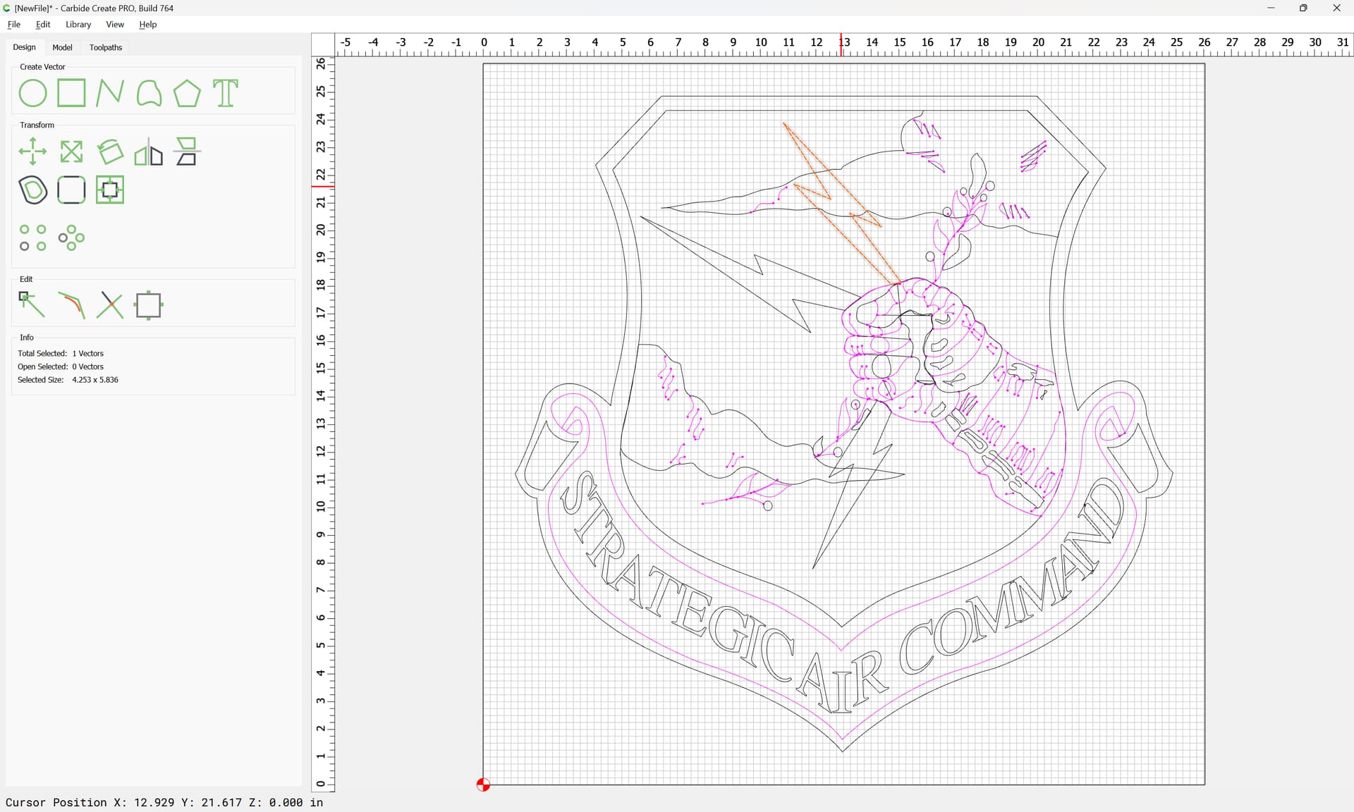
Perhaps my first attempt is too complex, but this is what i want a cnc for
Can you post an example image and what you want to do?
1 Like
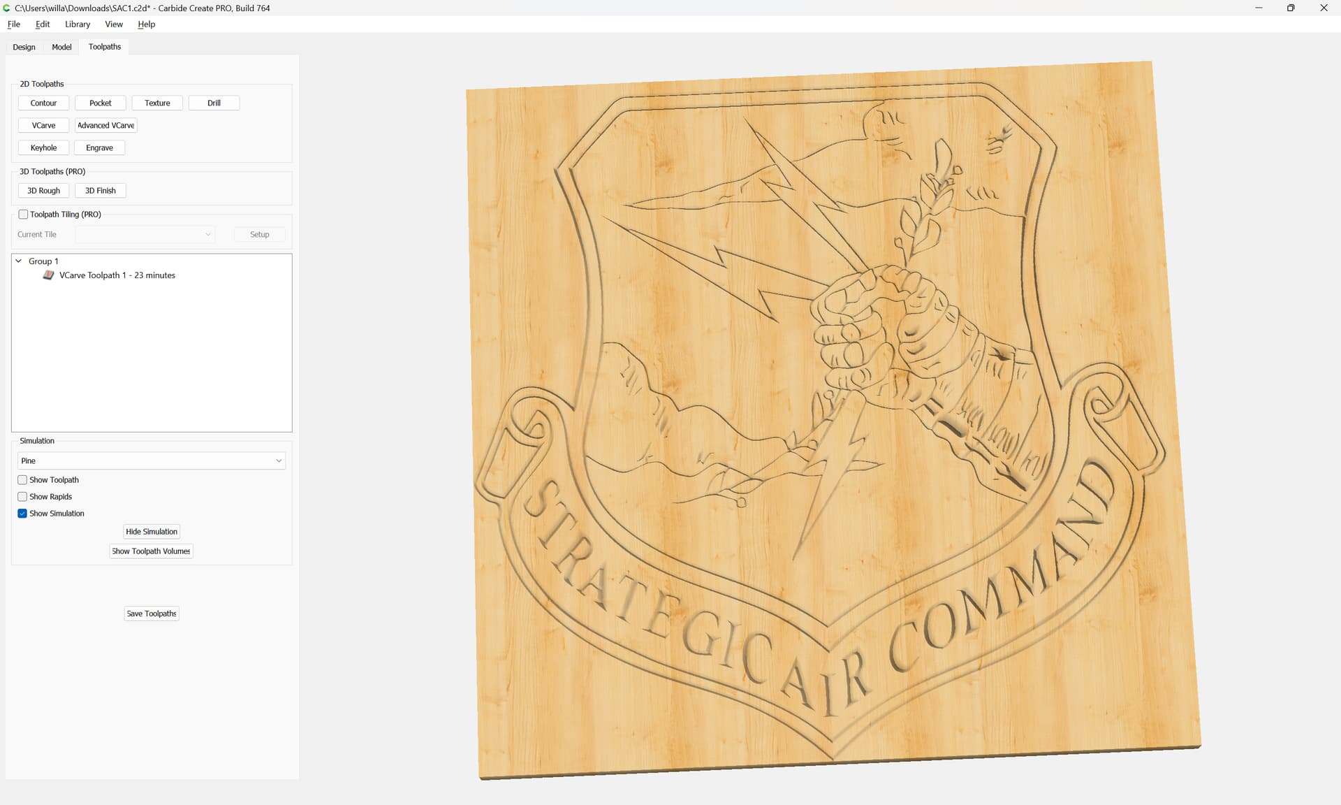
so that image will work well as a V carving project. If you want to make it 3D with rounded details you’ll need an image with shading and you can load it into Carbide3D that way. Darker goes deeper type deal. Otherwise STL files you can 3D carve fairly easily, just takes time.
The C2d image is attached above, I would like the fist, clouds, and inside of shield to be different depths.

Right now it only carves the lines, and the lines are evidently too thin, it forces me to show with a 1/32 bit, anything larger and it doesn’t show is cutting.
As noted that vector version of the SAC shield should cut well as a V carving:
It doesn’t lend itself to cutting different elements at different depths because a single piece of geometry:
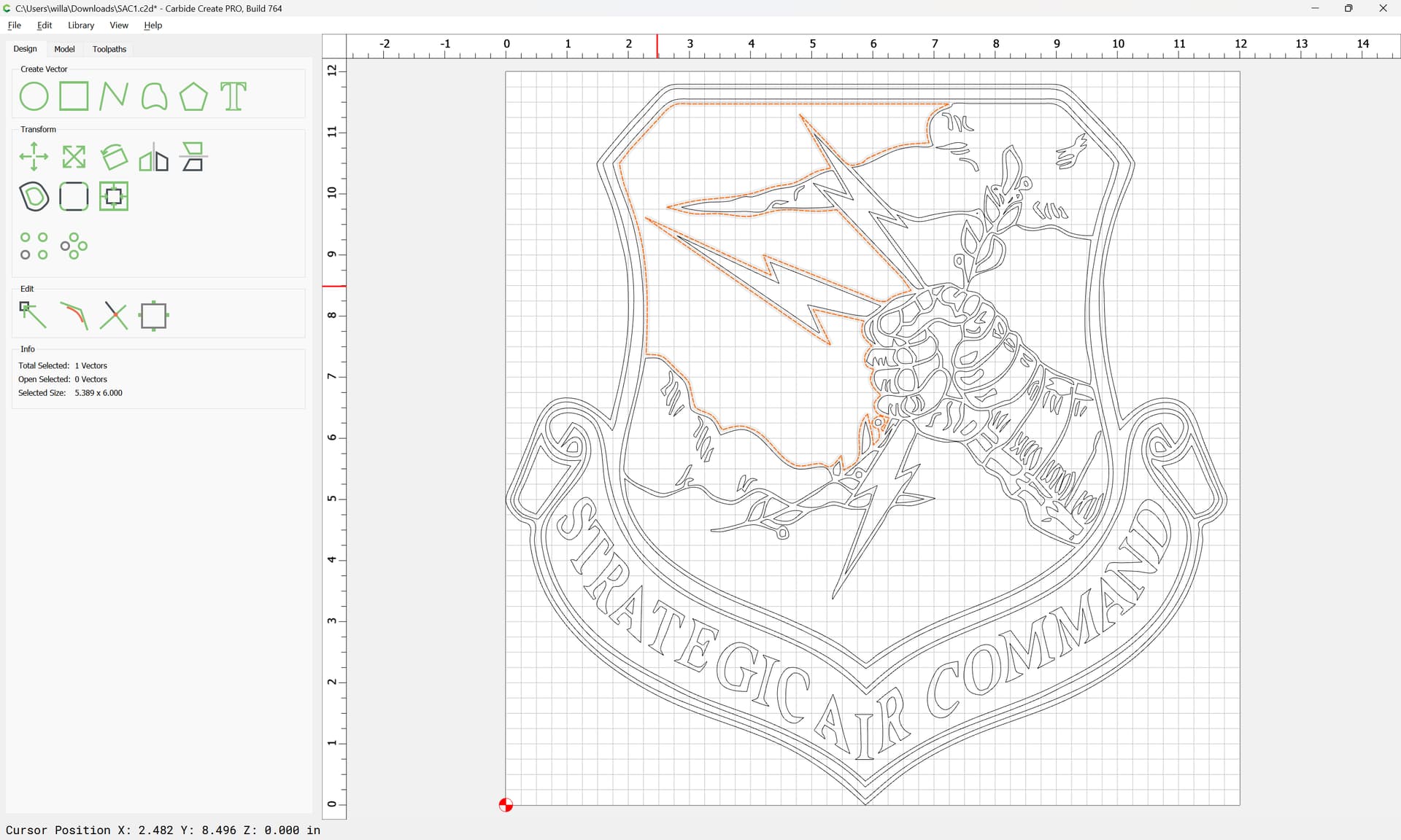
will describe the outlines of multiple elements of the design
You would want a colour version:
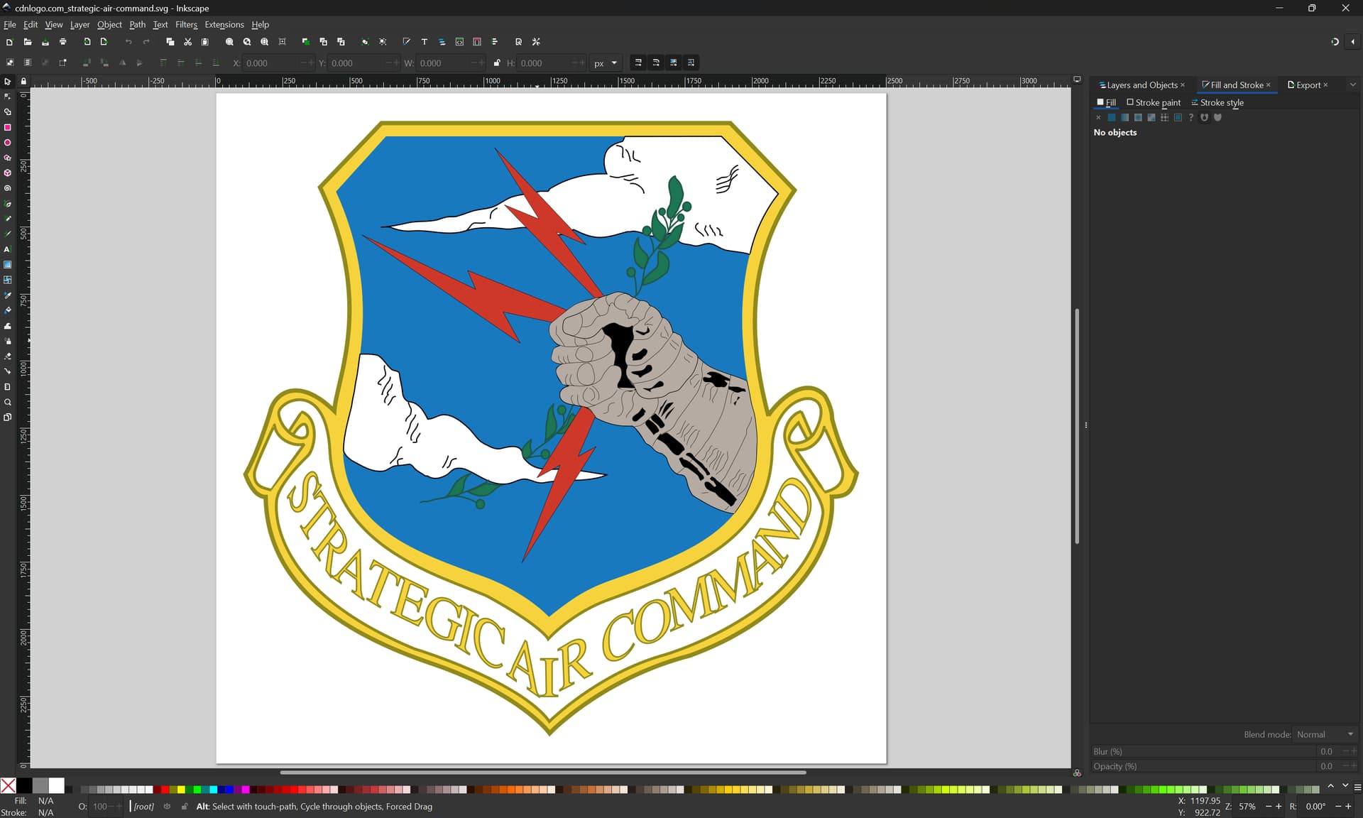
if only it were drawn so that each element when selected would have an outline which would describe only the visual area of it — which is not the case:
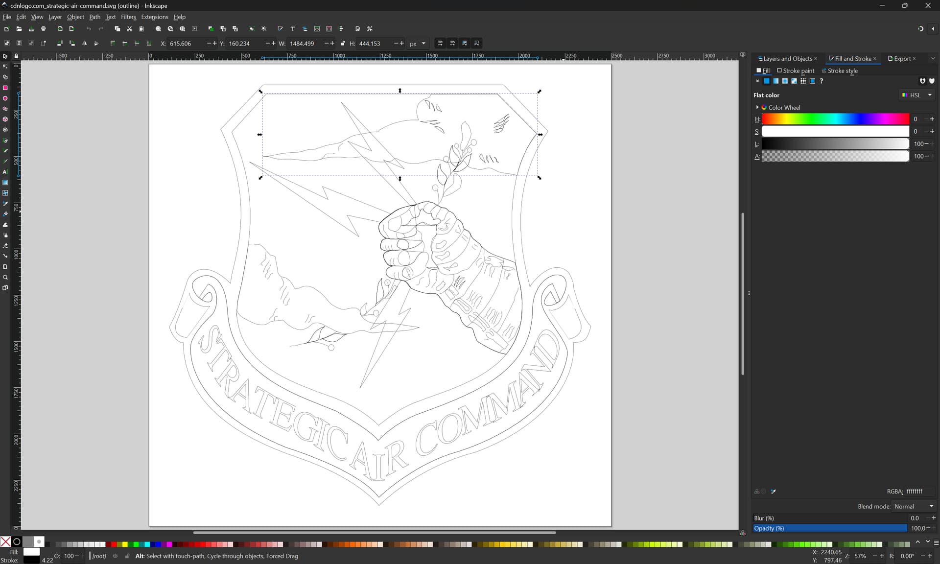
For a bit on fixing this sort of thing see:

Basically, you’ll need to duplicate all of the overlapping elements and use either Trim Vectors, or Boolean Subtraction to arrive at geometry which describes only the visual portion of each element in a way amenable to how you wish to cut the design.
Thanks
This is the conclusion I came to, but I haven’t figured out how to do it all in C3, so I’m creating layer images in photoimpact then going to pull them in seperate. ugh !
As i said, I’m still learning Carbide Create, Haven’t figured how to do it this in it
1 Like
I didn’t think that’s necessary or the best way. I’d do it all in inkscape.
1 Like
Guess I need to learn inkscape.
It’s a valuable skill — this sort of thing can be done in Carbide Create as well, but if you’re inclined, Inkscape is a quite capable program — the big thing is, all of these programs use the same underlying concepts, and facility in one transfers to the another.
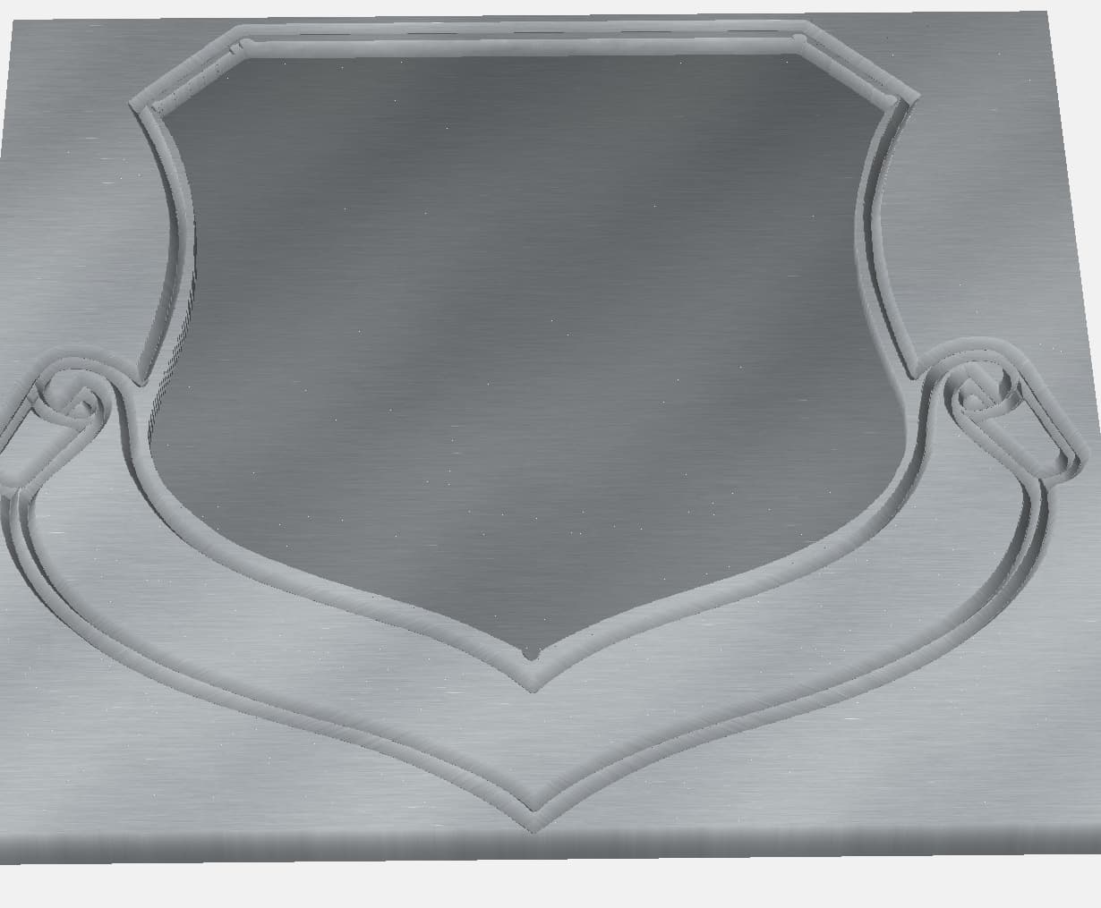
Well, was quite the beginner learning lesson, but it’s 99% done. I missed 1 little piece which I may not try and fix if it breaks the rest of the image. Not exactly sure How I did it all, but it’s pretty cool.

I bought a used machine Wednesday, so will build a table tomorrow and then put it together.
4 Likes
This topic was automatically closed 30 days after the last reply. New replies are no longer allowed.