Creating 3d Path that is half round

I have read through Will Adams Github document but still dont understand how to model in Carbide Create 3d. The attached file is a project that holds a whiskey glass and a metal tray to be used as an ashtray. The center I want a half round place to place an un-smoked cigar. After I learn how to make the 3d image I want I will also make the same shape perpendicular that goes across the ash tray to become a resting area for a lit cigar.

Can someone please point me to a tutorial about how to make an image that is 1" wide and 8.5" long and is the shape that is half round. The reason for the 1" wide is the largest cigar ring gauge is 80 and that is around .9" and I want it about .5" deep.

I am not asking anyone to make the shape for me but rather how to make the shape.
This file was generated in CC v7 710.
whiskey_cigar.c2d (668 KB)

I am making an assumption that you are using the free version of Carbide 3D. If that is the case the way I would do this is to purchase a 1 inch round bit and draw a polyline that is 8.5 inches long. I would then use a contour toolpath with no offset. Using your existing file we would get a preview like this. I do not know the proper feeds and speeds for this and if you are carving out of metal I am not even sure where to get a bit like that but many places seem to have one inch bits that could work with wood.

If you have the paid version of Carbide 3D you could actually use the rectangle you have and then turn that into a 3D object and have it round out. The carve would take way longer to get it to clean out the cavity and probably take a pass with a larger bit to clear the bulk and then a finishing pass with a round nose bit to clean it up. I do not have the paid version but have played with the demo a little. I am sure someone else can help with that better than me though.

I have the Pro edition of CC. So what would be the steps to create the half round with supported tools. My quest is to learn and right now I am not worried about how long it would take to machine the parts.

I tend to preview in Aluminum because many of the previews are hard to see with the wood textures. I will be using mahagoney to cut this project.

Thanks

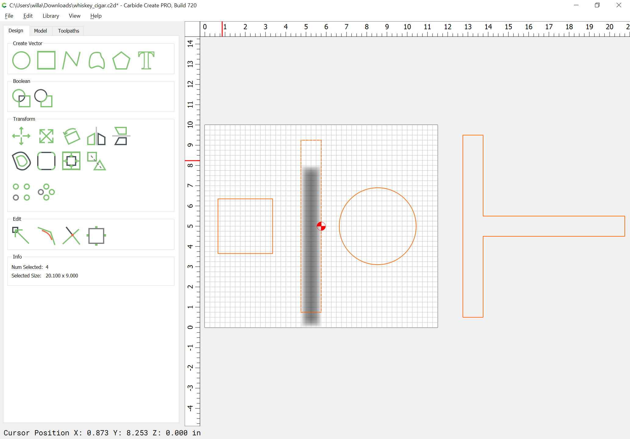
In order to get a complete half-cylinder you will need to continue the shape past the edge as noted in:

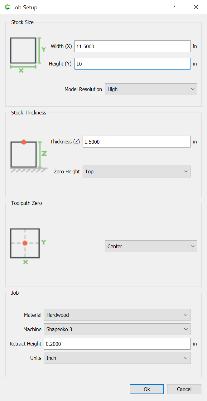
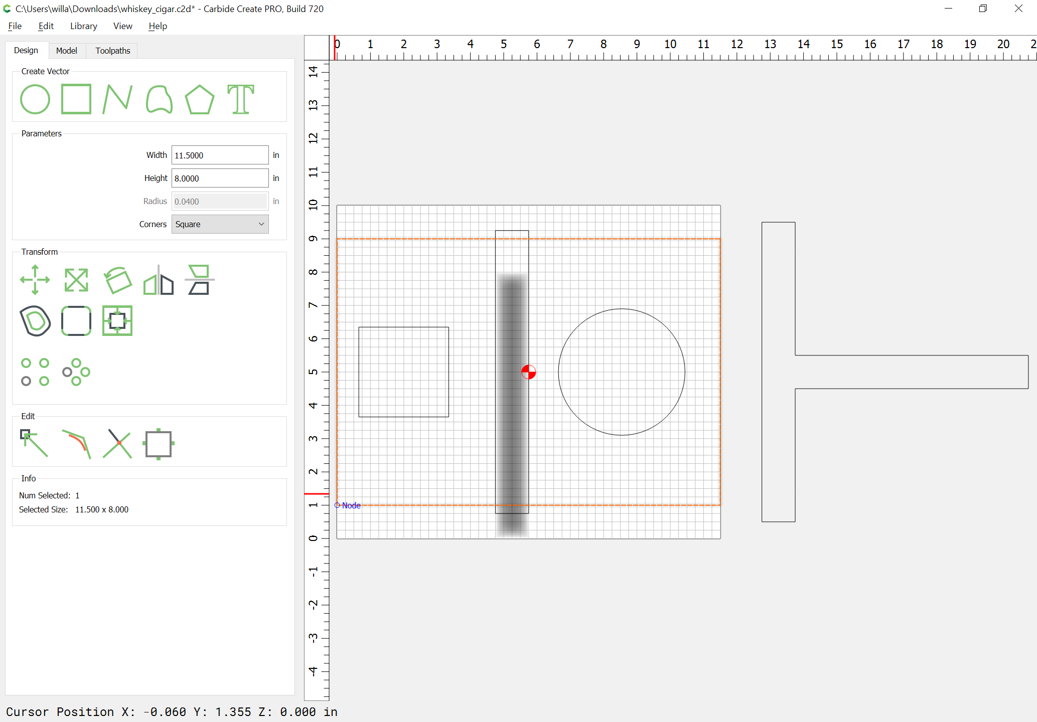
So increase the stock size:

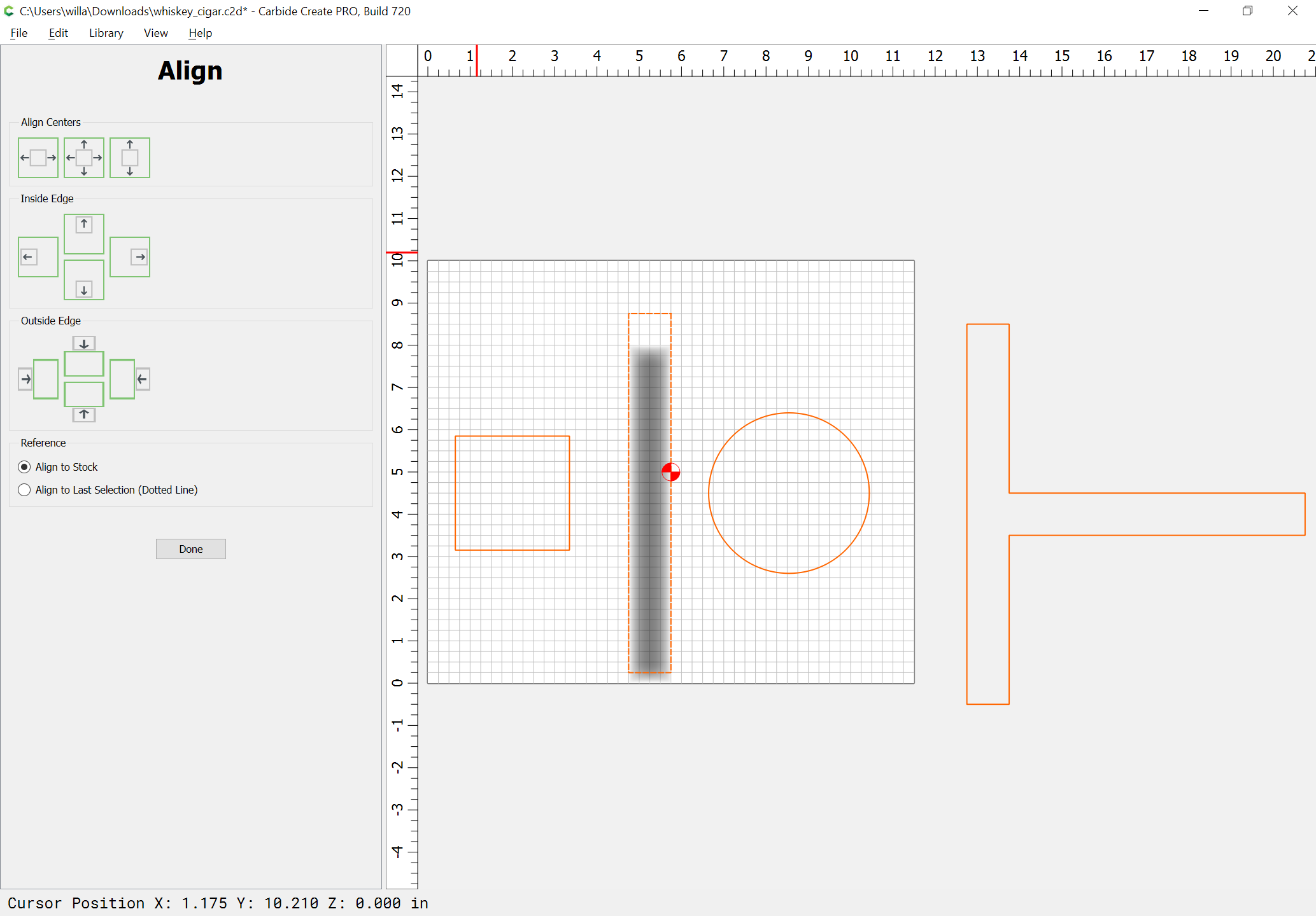
Align things to the stock:

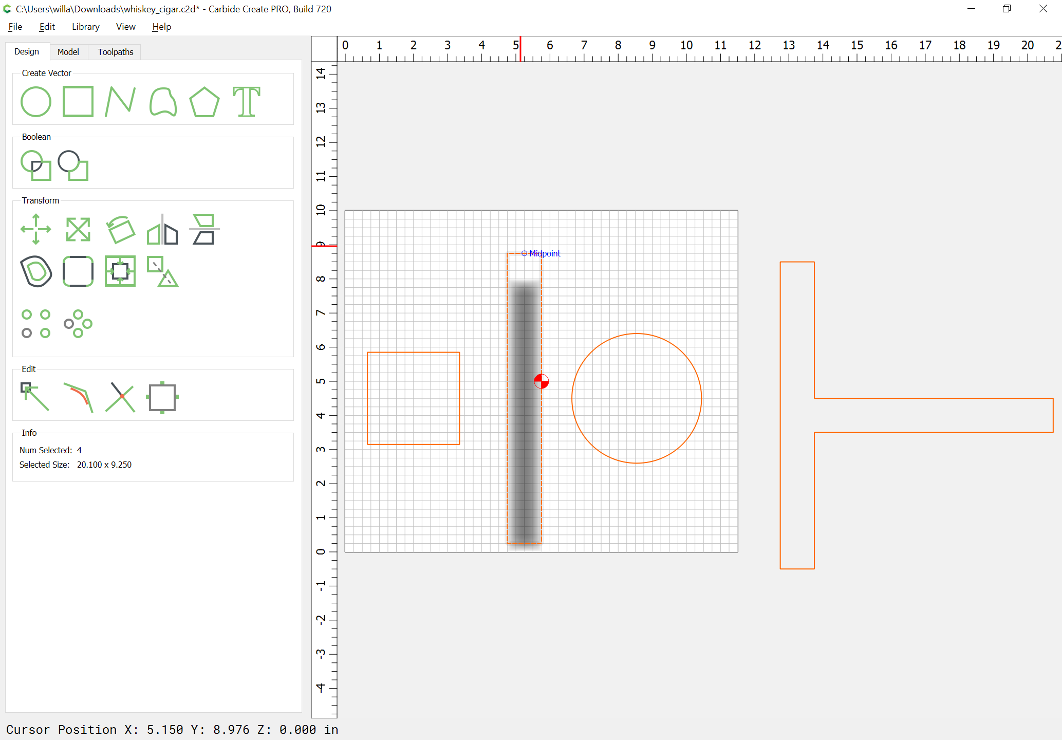
Draw in the desired area:

and increase the size of the cylinder:

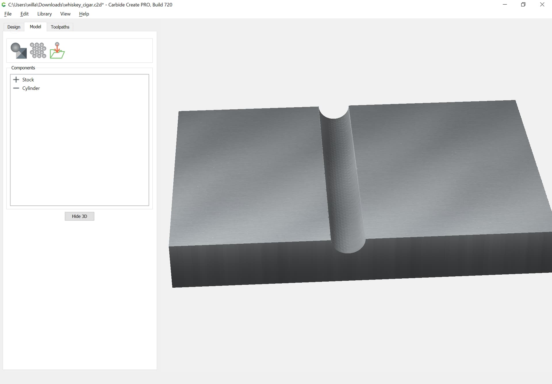
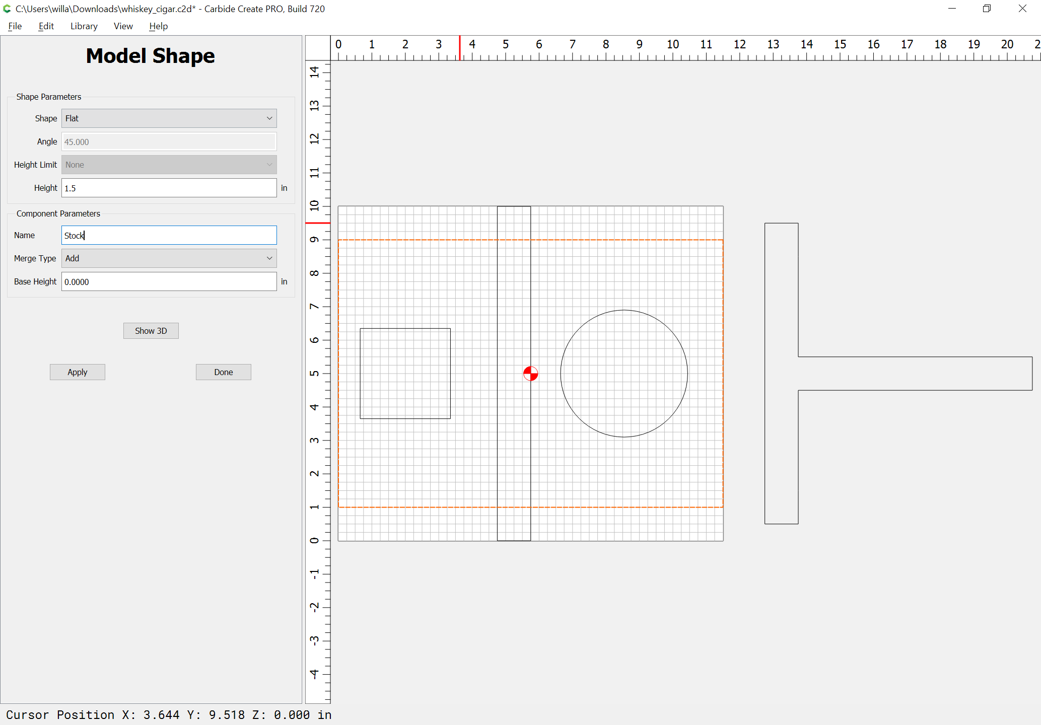
Then model the stock:

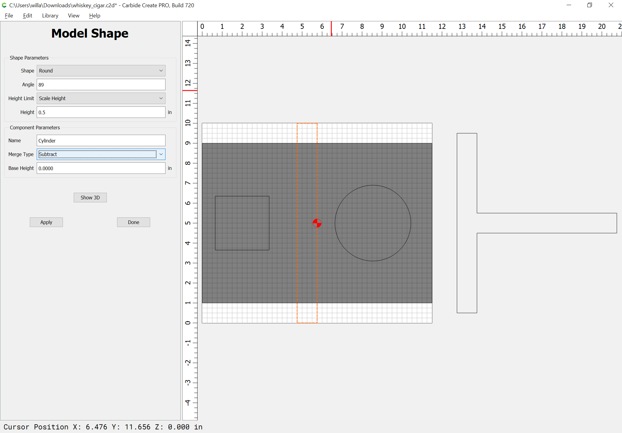
and subtract the cylinder:

@WillAdams thanks. I will try it. I found quite a few tutorials but they just hit the highlights and ever the nitty gritty of how to make a 3d object. Some of the tutorials showed how to import a png grayscale but again nothing I could sink my teeth into.

Thanks

So I think I have what you want using the demo version. Make a rectangle about 11.5 * 9. and extend your cigar holder rectangle to 9 inches as well.


Select the large rectangle that is now as wide as your project and as long as the cigar holder. Go to the Model tab and click the Add Shape option and select Flat with a height of 1.5 which is the thickness of your project. Name it and select Add as the merge type. Base height 0.

Next select your cigar holder rectangle and click Add Shape again. This time choose Round Angle 45 and Height Limit if limit height. with a height of 0.5 Name it and select the Merge Type of Subtract with a base height of 0.

Next go into the Toolpaths tab and select the cigar holder rectangle. Click 3d rough and choose a ball mill that you have and works for you. I selected a 1/8 in the example.
Stock to leave is 1.

Next click 3D finish and select a smaller ball mill. You can choose and angle if you want it to move something other than back and forth.

This gives a simulation like this. It is not great in simulation but I think this should work.

I figured this out from this video. It did not give all the details but pausing in a few key places helped me figure it out.

Hopefully someone with more experience here can tell you if this is right or not but it seems to wokr based on the simulations I see.

1 Like

Well I guess @WillAdams beat me to it.

Thank you Ryan. I had watched that video you referenced but I believe it was from 2 years ago and it was as clear as mud to me. I am a slow learner but once learned I never forget. The 3d imaging is stretching my brain and it is not particularly elastic. Thanks for contributing.

I was having a lot of trouble with this the other day. I am glad I spent the time figuring it out here. It may actually push me to make the purchase. I was trying to do a relief map and could not figure it out for the life of me. It was the need to build the base first that threw me. The idea that I needed a 3D shape the size of my object first and then I could subtract from that is what finally made it click. I could only make it look like the object was either not present at all or it was the inverse of what I wanted. That YouTube video did not explain it well but when I saw that @wmoy made the beveled object first and then subtracted the tray from it is what made me try that and did it.

I got the modeling done and in @WillAdams instructions I increased the stock size from 11.5 X 8 to 11.5x10. In the simulation the increased stock size shows a cut out on the extra 1" on both sides. What will actually cut or happen if my stock is actually 11.5 x 8 will the cutter cut down in the air but still cut that shape in the simulation.

whiskey_cigar.c2d (688 KB)

Make another rectangle the size of the slot.

This rectangle is to build the model

image

This rectangle is the boundary for the toolpath

image

1 Like

Assuming the stock is actually 8" deep, I would recommend making the rectangle that height, plus the diameter of the tool:

That way the toolpath will cut to the edge of the stock:

I tried that & the cut wrapped around the edges. If this is what’s wanted it’s OK.
Small mismatches between paths can make the corners look rough. I don’t like the wrap-around effect.

I would finish this at 90° as well, which runs the passes all the way to the edge, and will give a better finish in the groove.

You’re only adding the radius at top/bottom — it should (edit) not be possible for the tool to fit down inside.

If you extend the boundary, it rolls around the corners

image

If you don’t, the rough pass looks good…

But the finish pass doesn’t quite make it to the end of the slot.

But if you change the direction to 90°…

Where the finish pass is falling short on the edges is not the radius of the cutter. (My grid lines here are 0.0625")

This topic was automatically closed after 30 days. New replies are no longer allowed.