Creating a catch tray with 3D design

as requested on support…

Given a vector design:

and

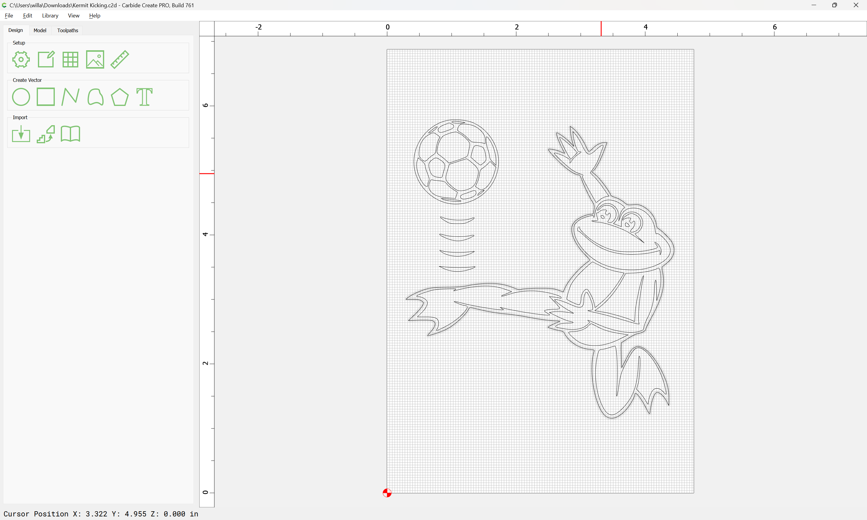
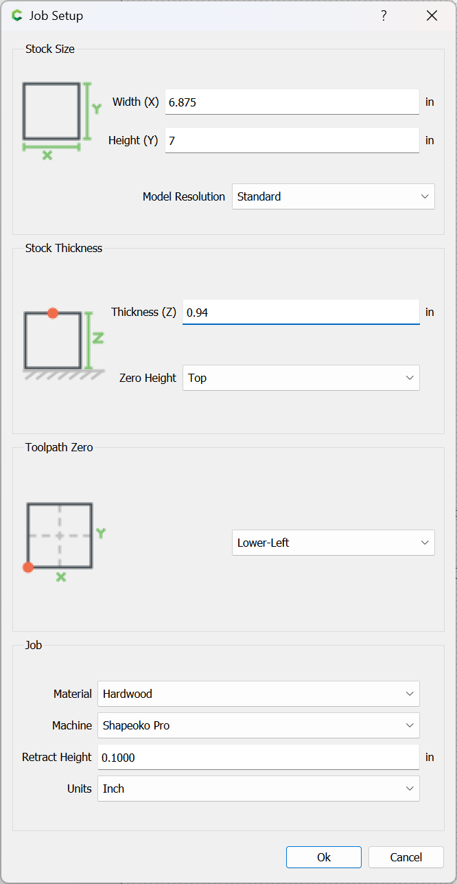
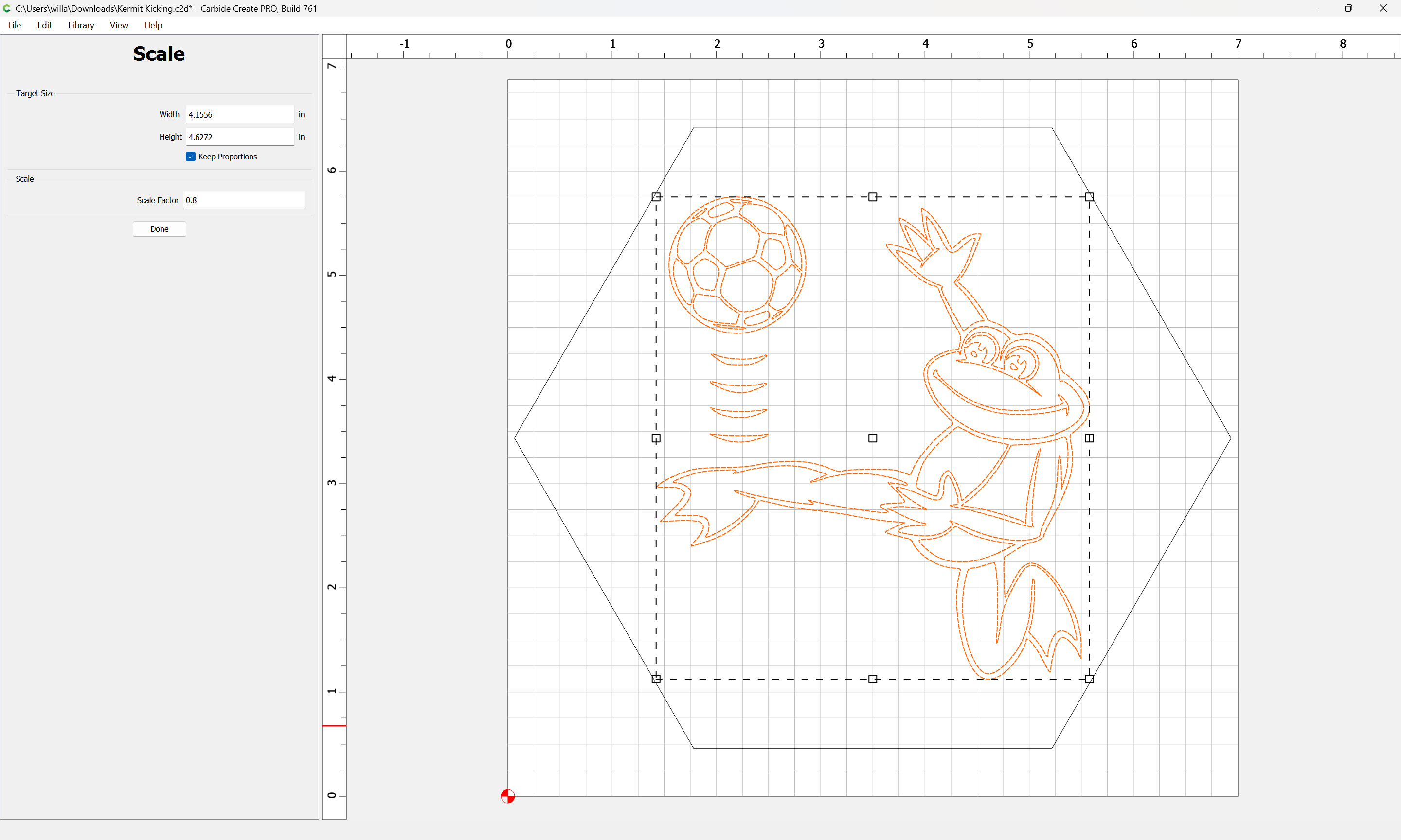
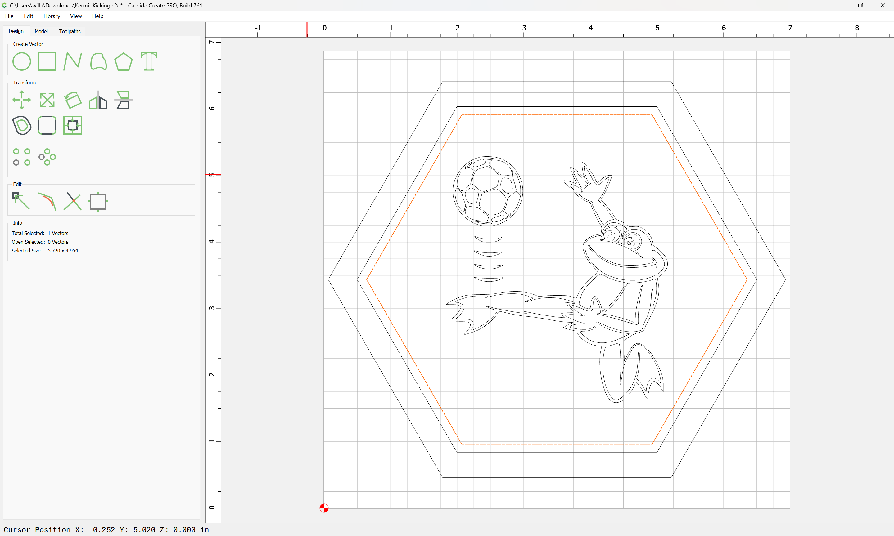
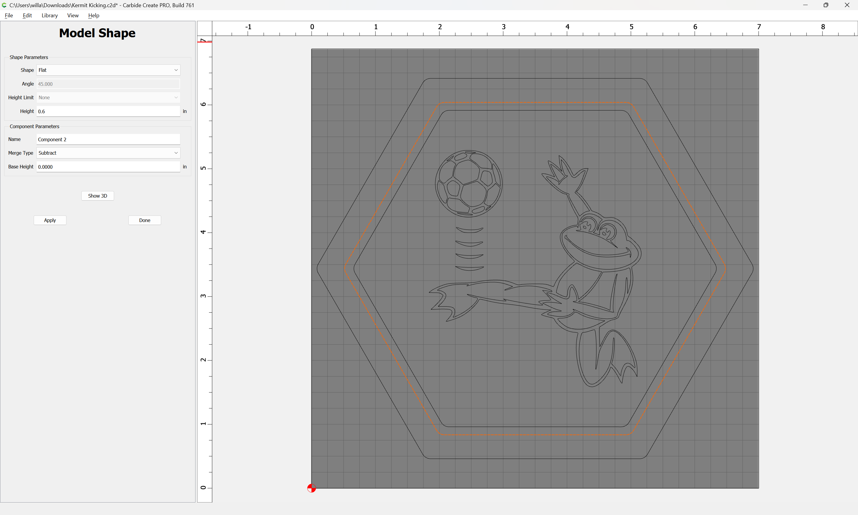
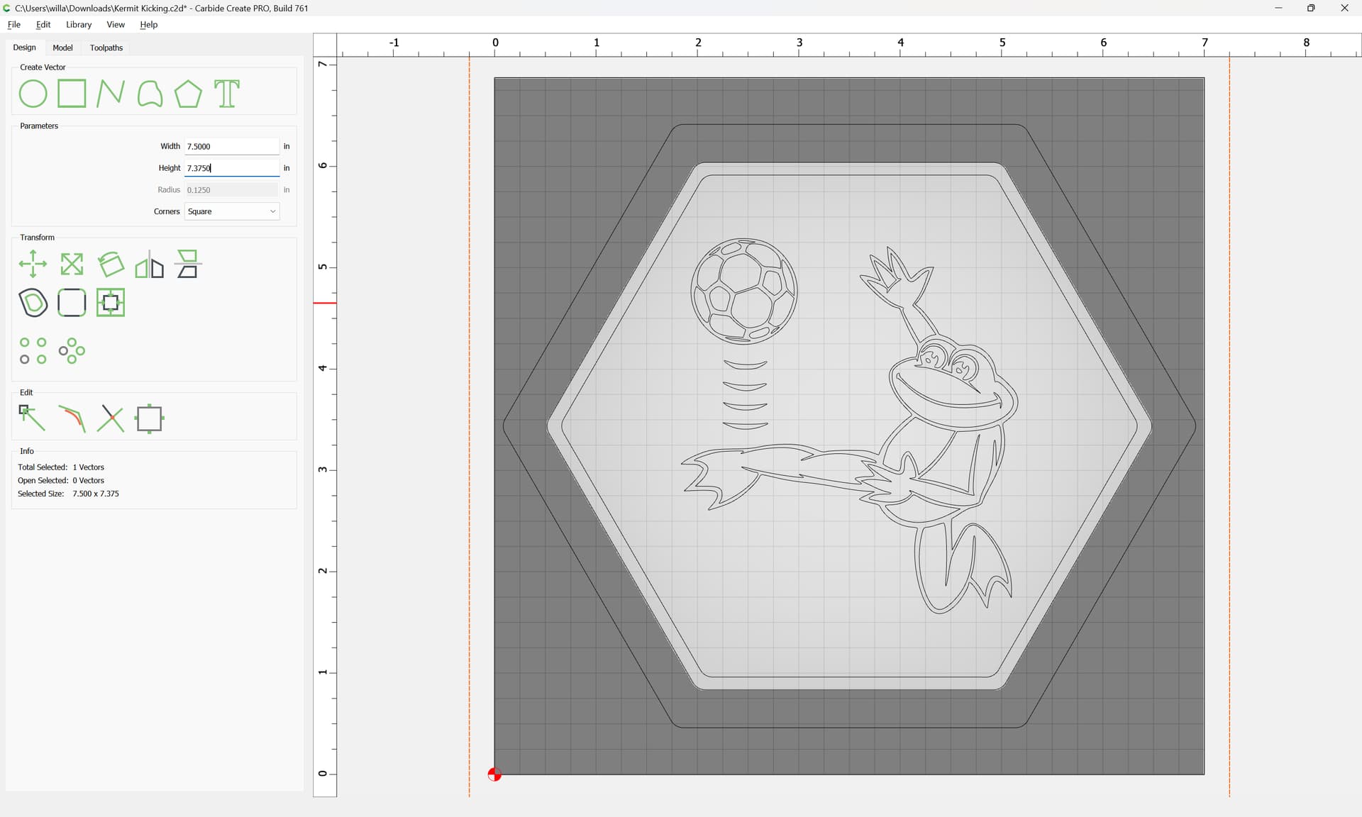
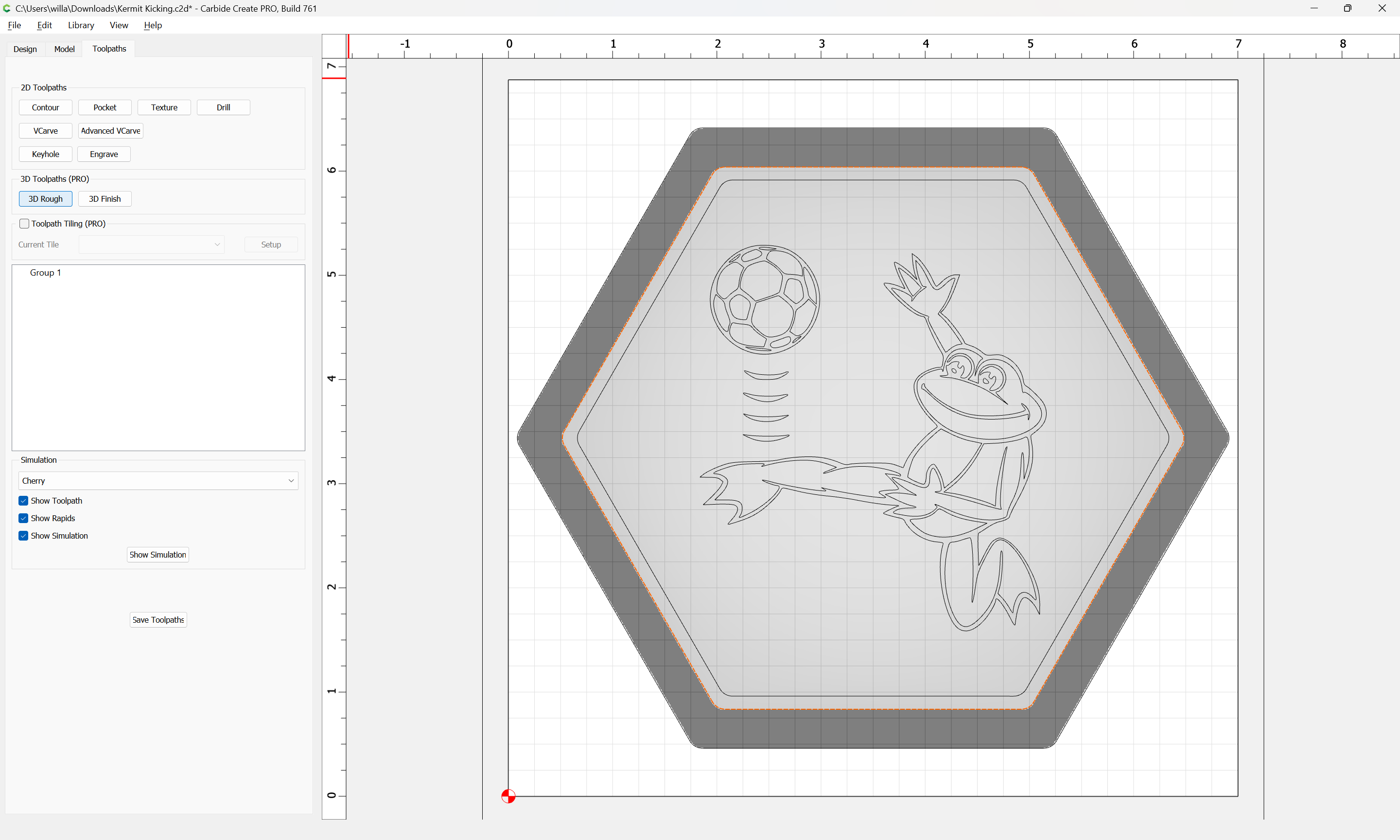
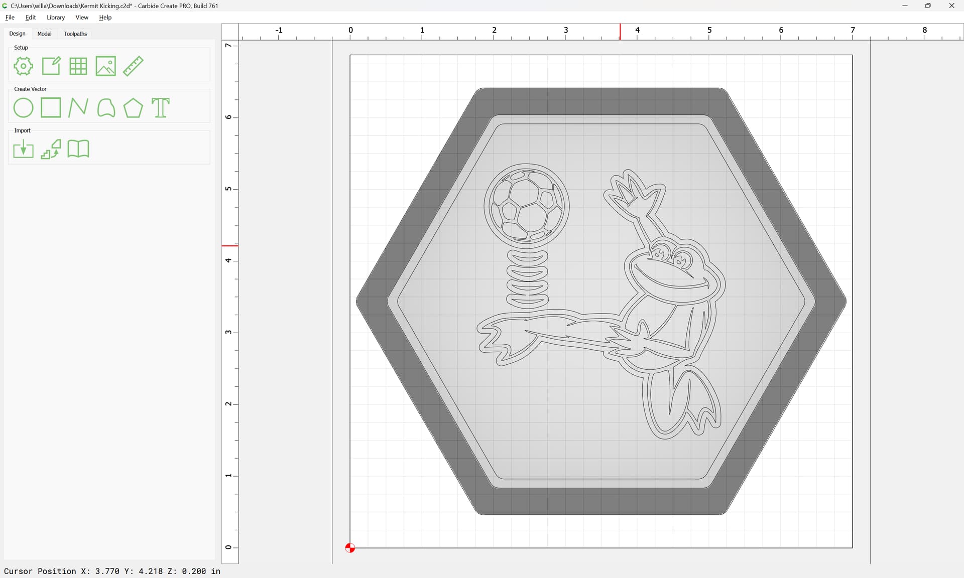
stock size is 6 7/8 inches wide X 7.00 inches high and .94 inches thick. I was thinking about a hexagon patter with a 1/2" border or maybe 3/8" border.

one would make a

3D Catch Tray

by:

first, setting up the stock:

and then drawing in a hexagon:

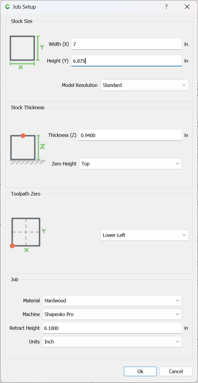
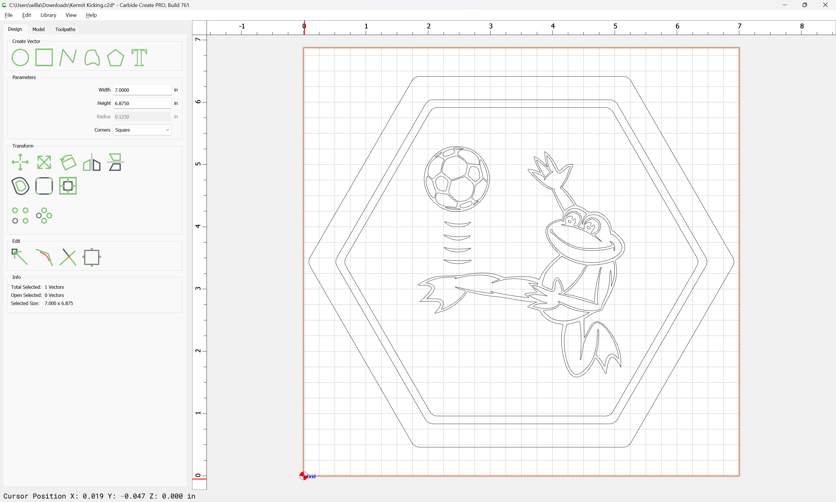
since the shape and design are wider than they are tall, it is arguably better to rotate either the stock, or the geometry by 90 degrees — this is most easily done by rotating the stock:

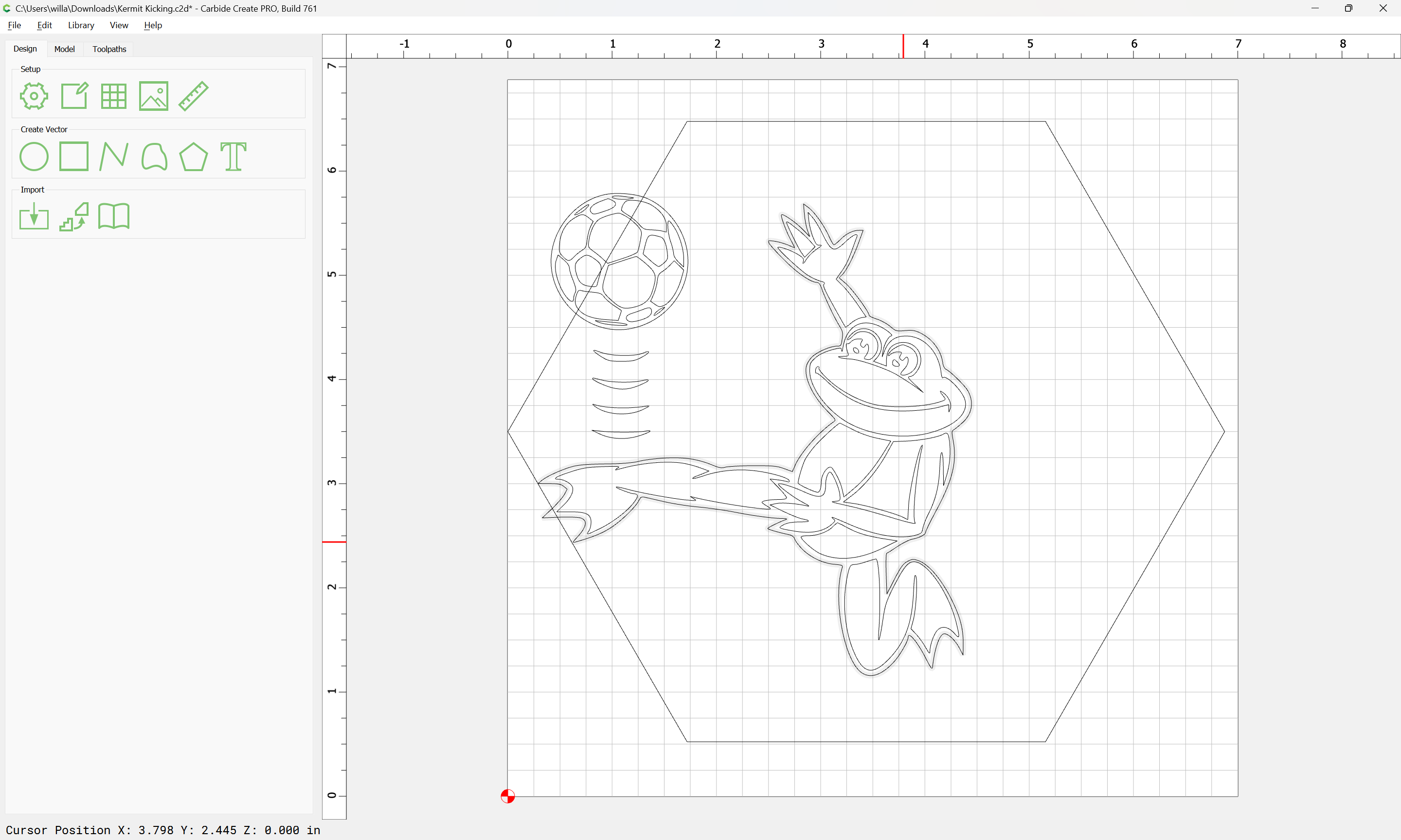
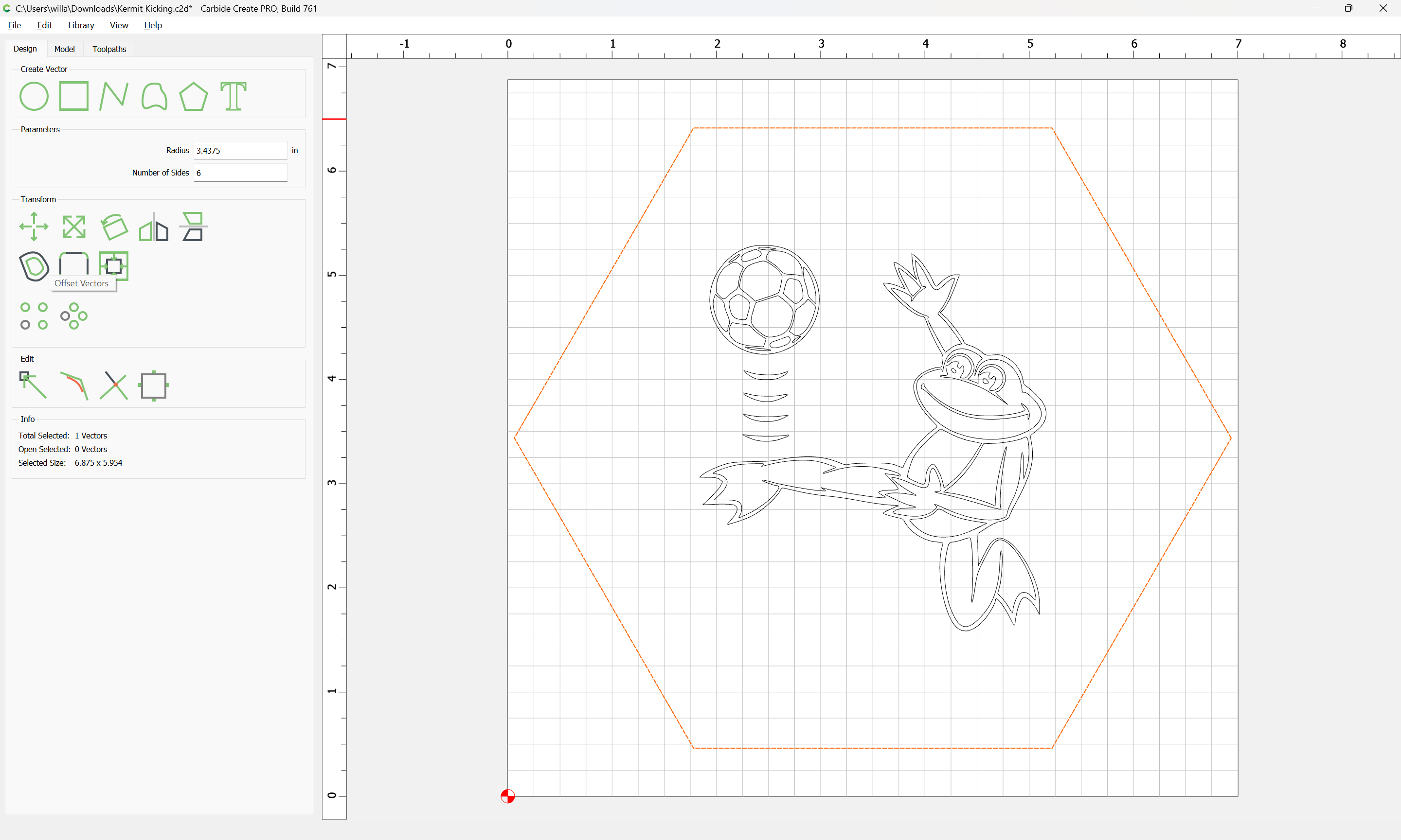
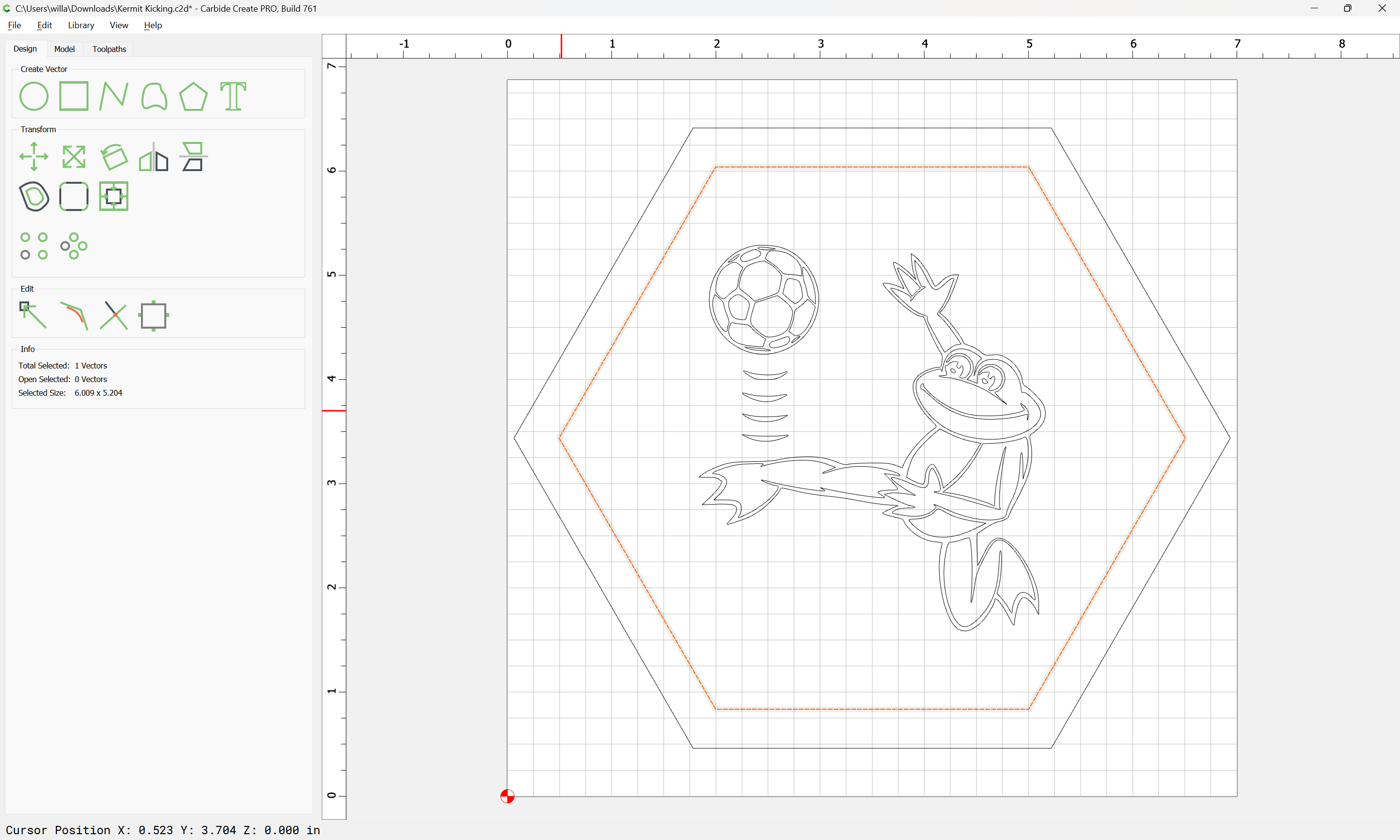
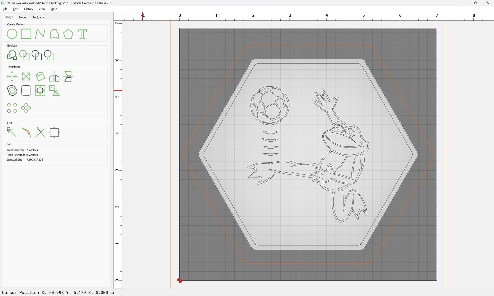
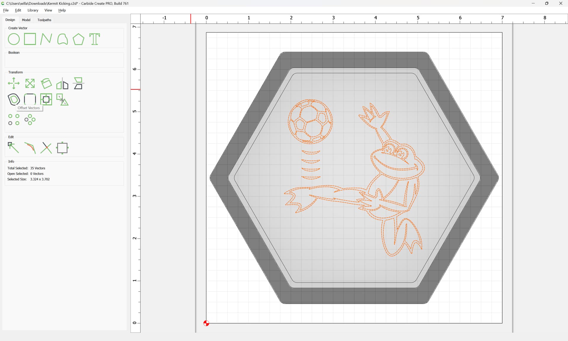
Since we won’t want to worry about exactly lining up the stock, we’ll want a bit of space around the outline to the sides which is easily done by aligning to the center of the stock:

The design itself should be selected and grouped:

and positioned:

and since we want the design to be comfortably inside things, reduce it a bit:

Done

Next we need the border, 0.375" seems workable, so we select the hexagon:

and inset by that:

Apply

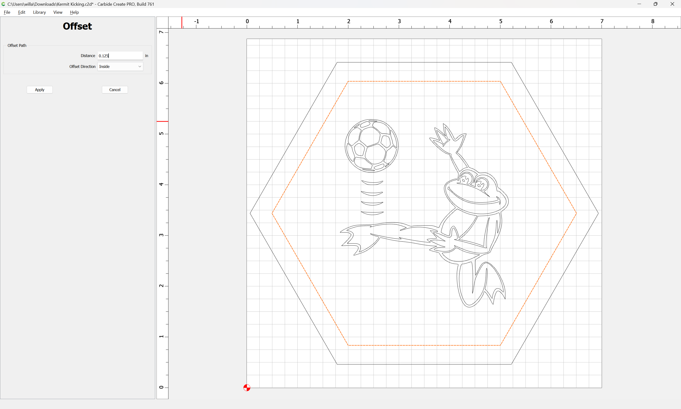
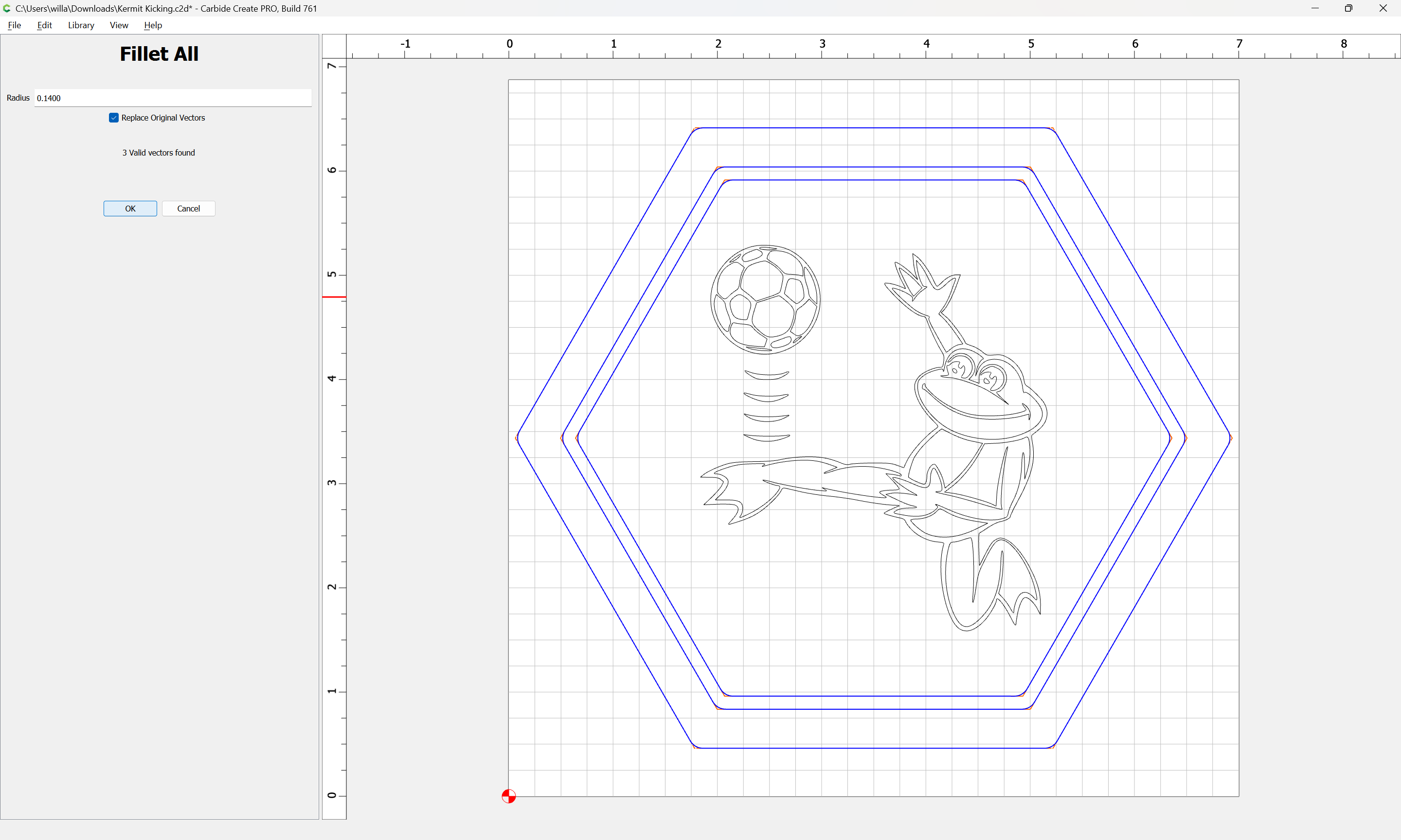
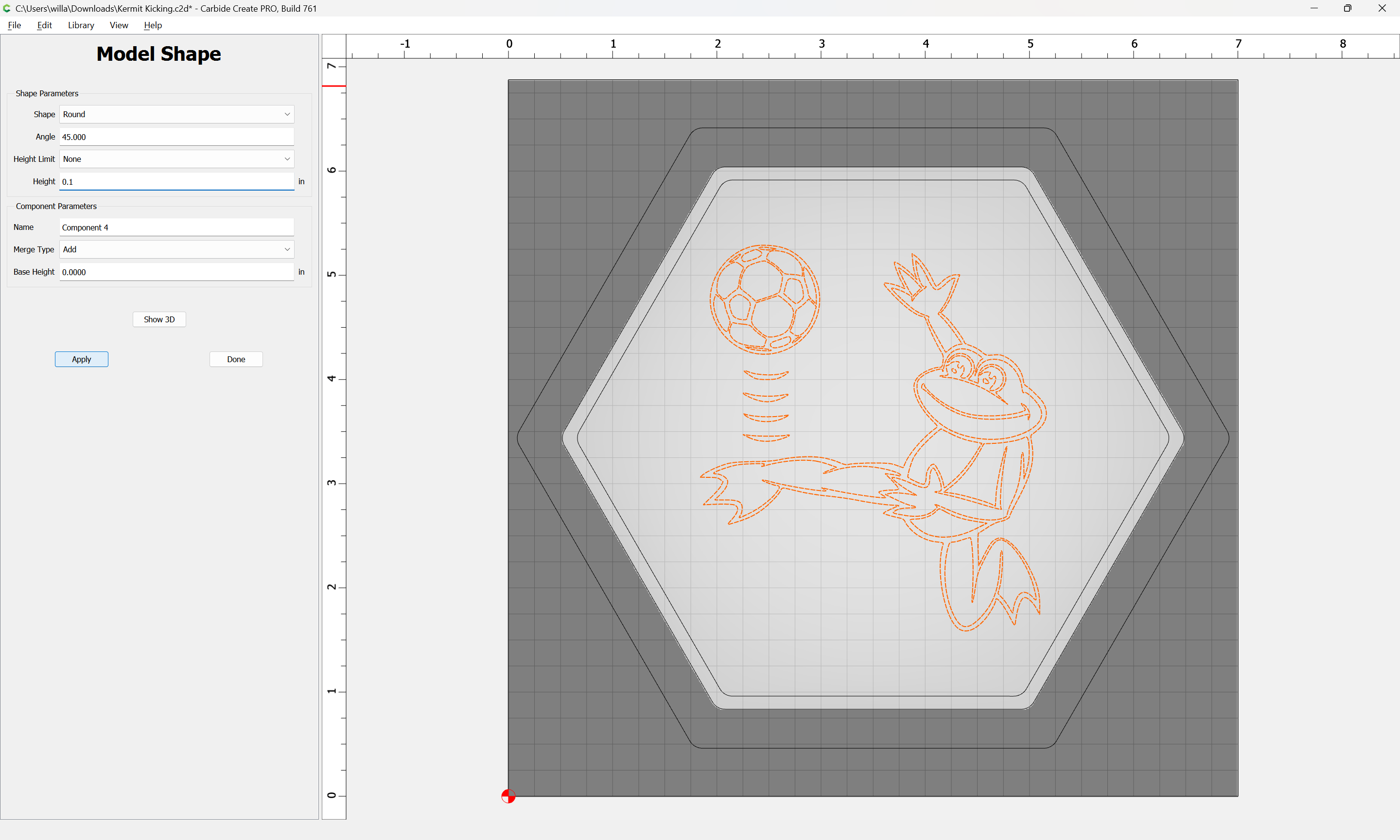
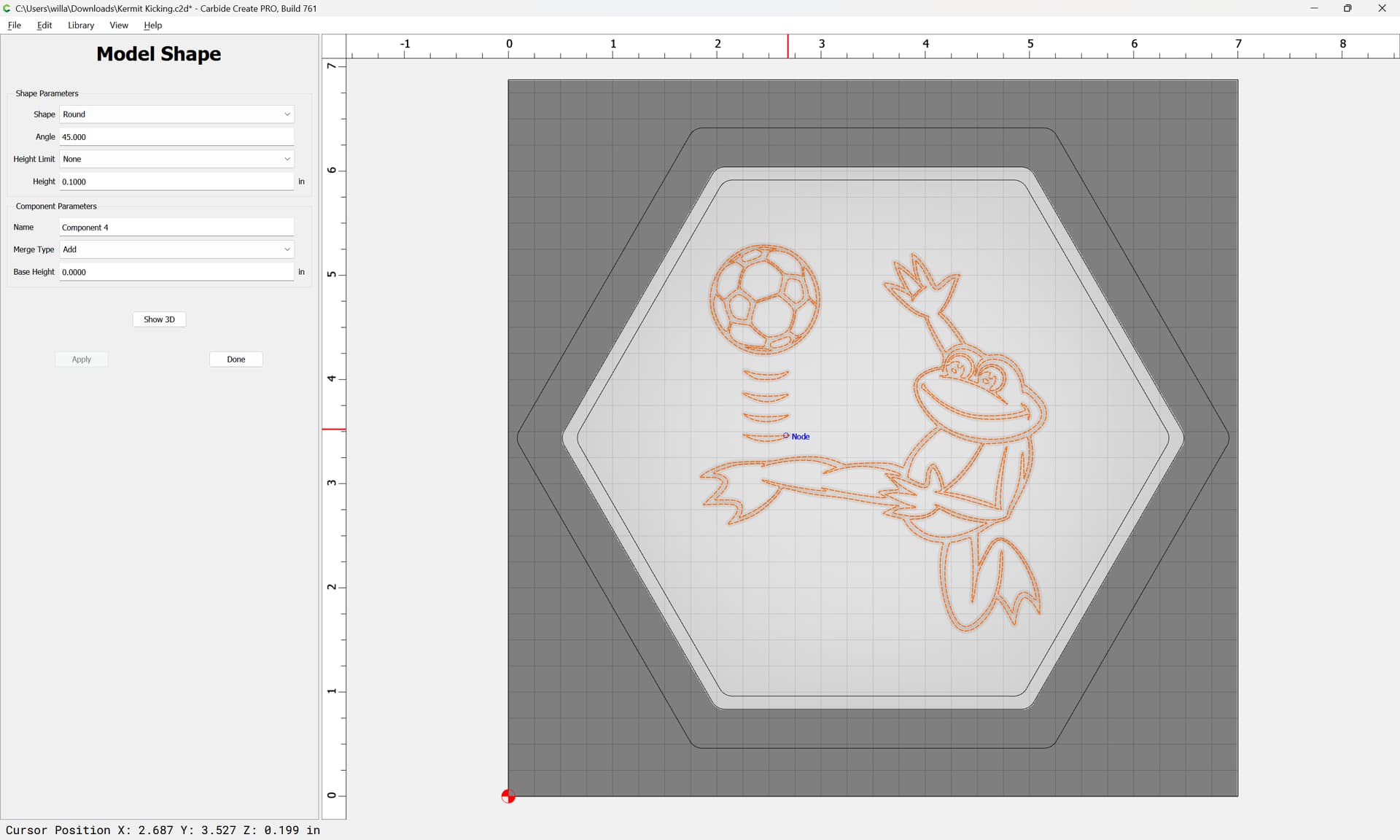
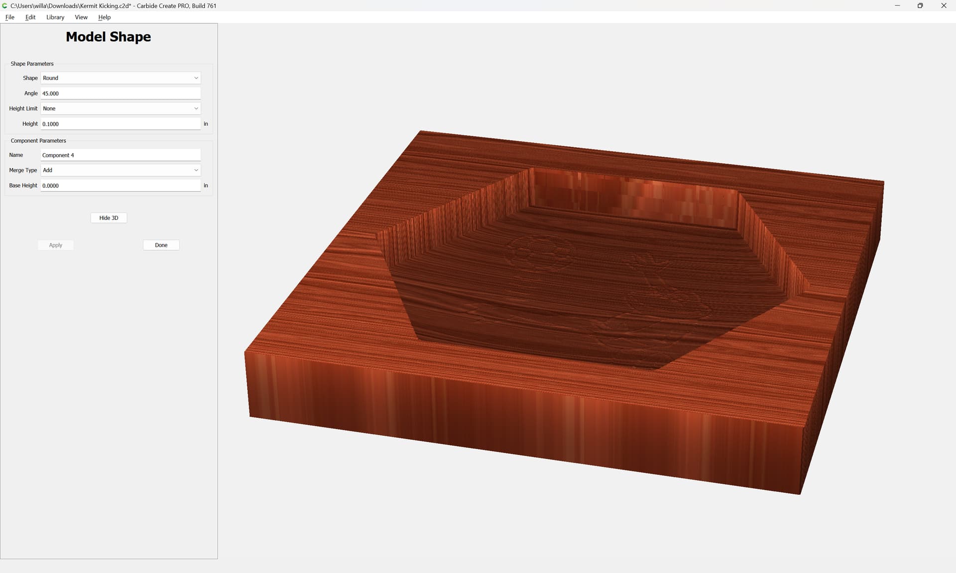
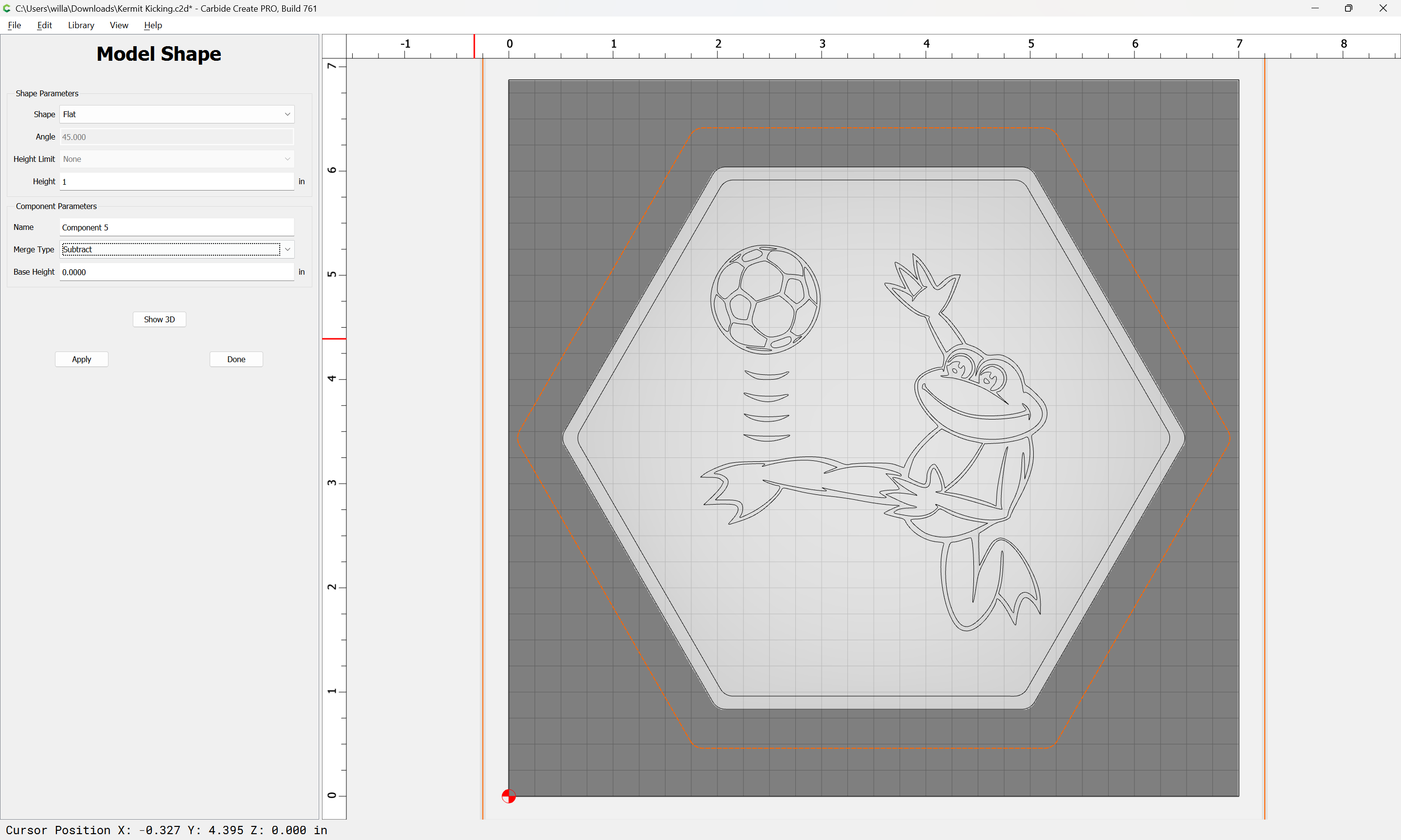
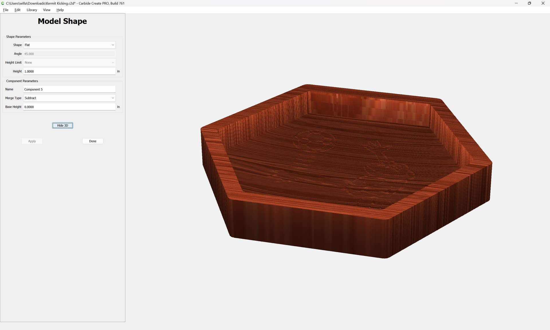
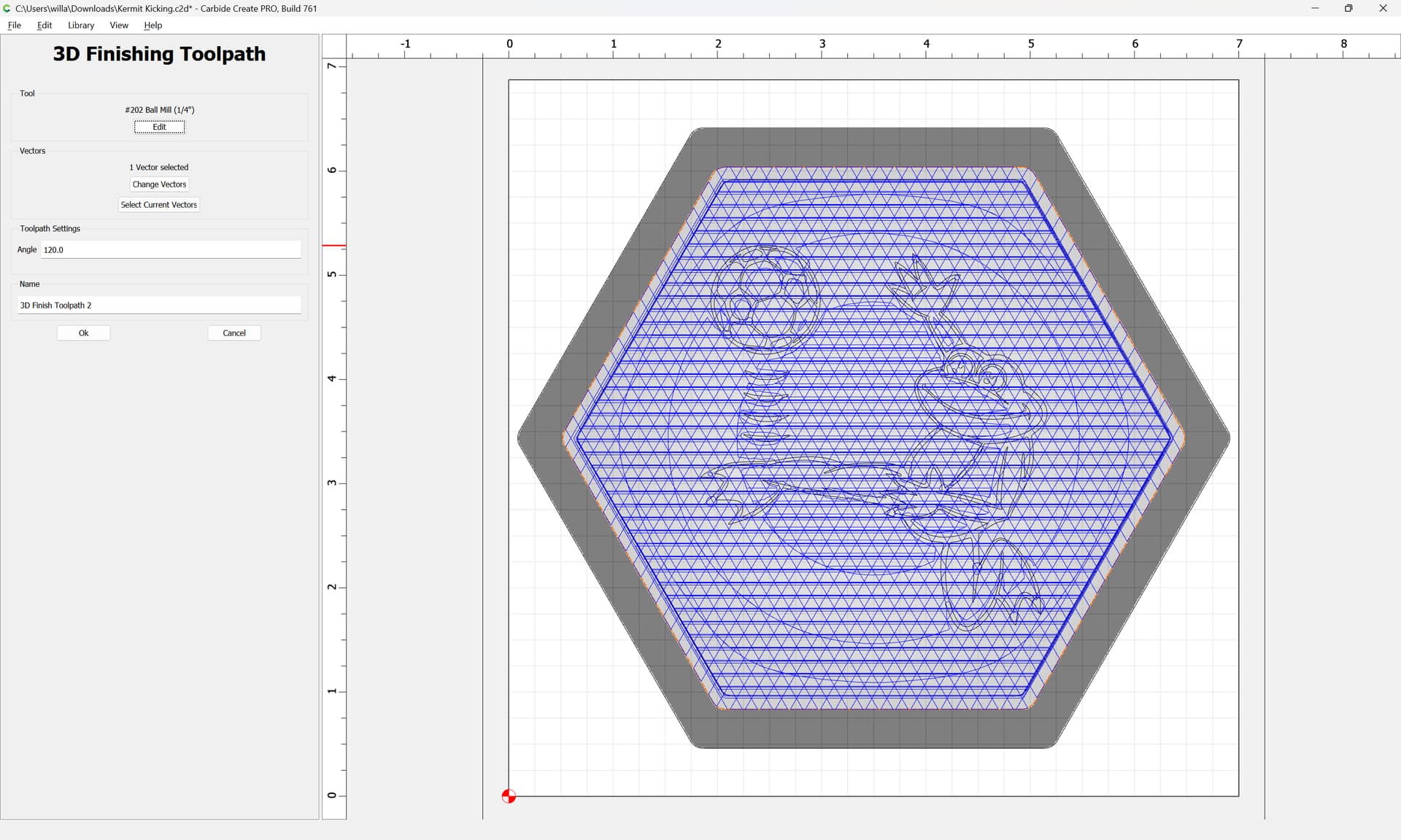
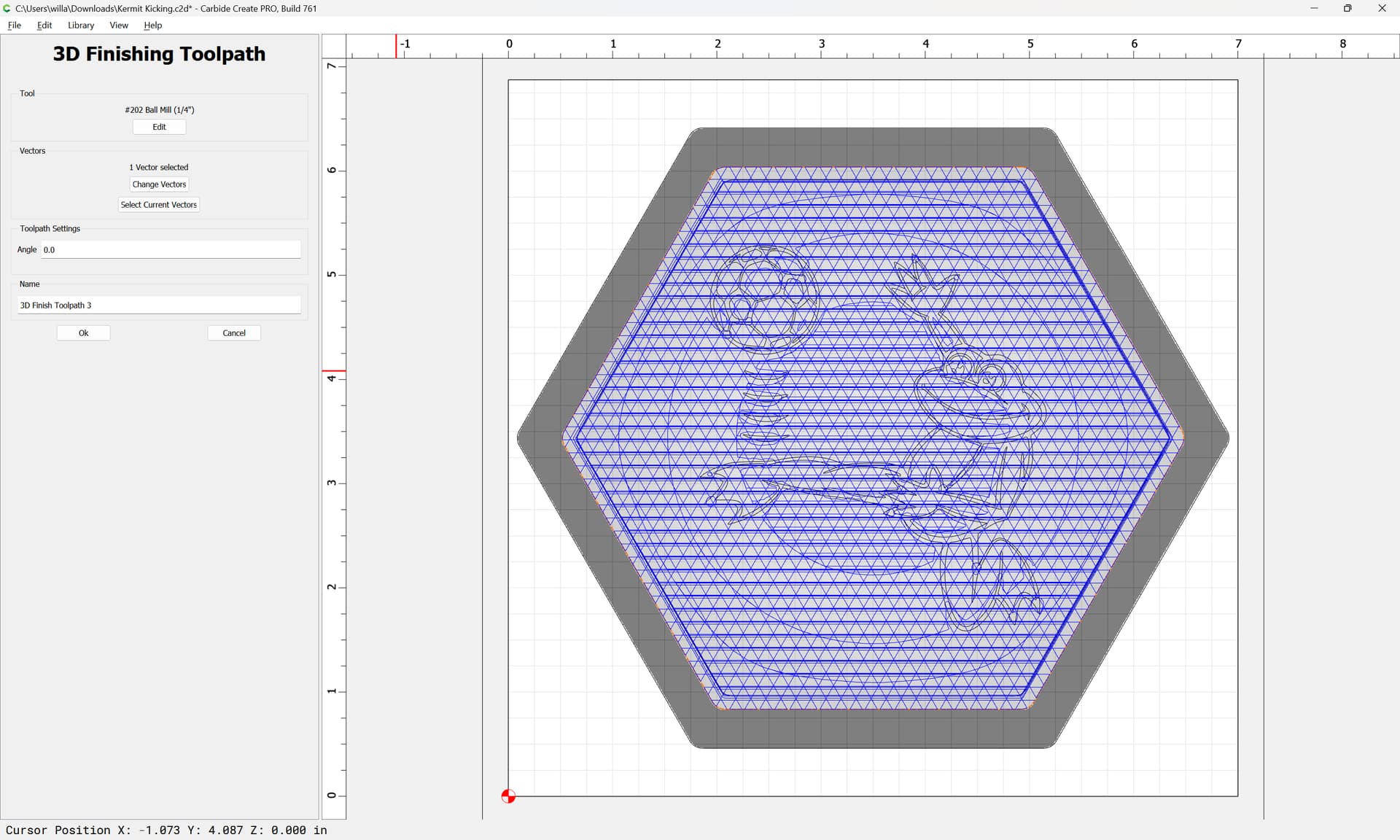
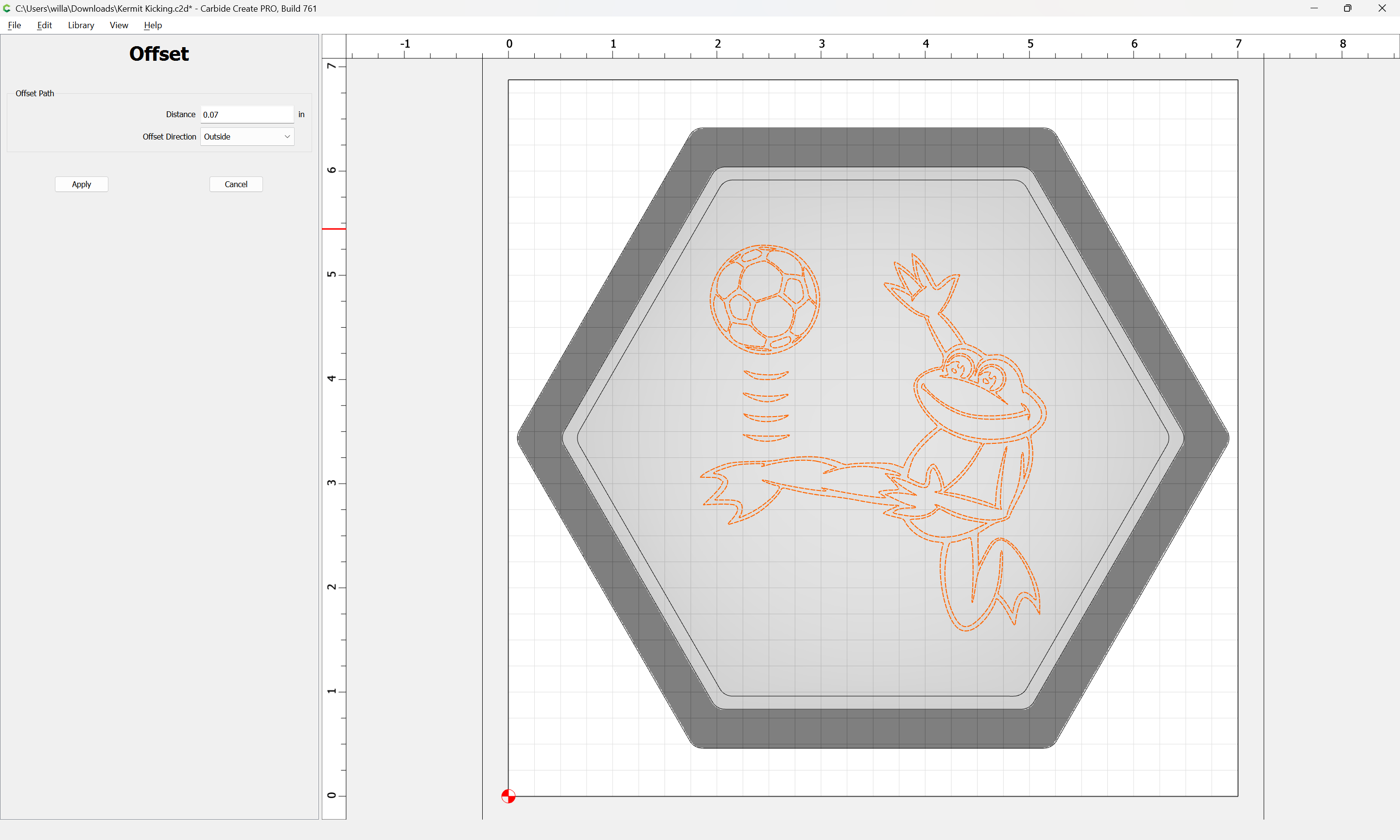
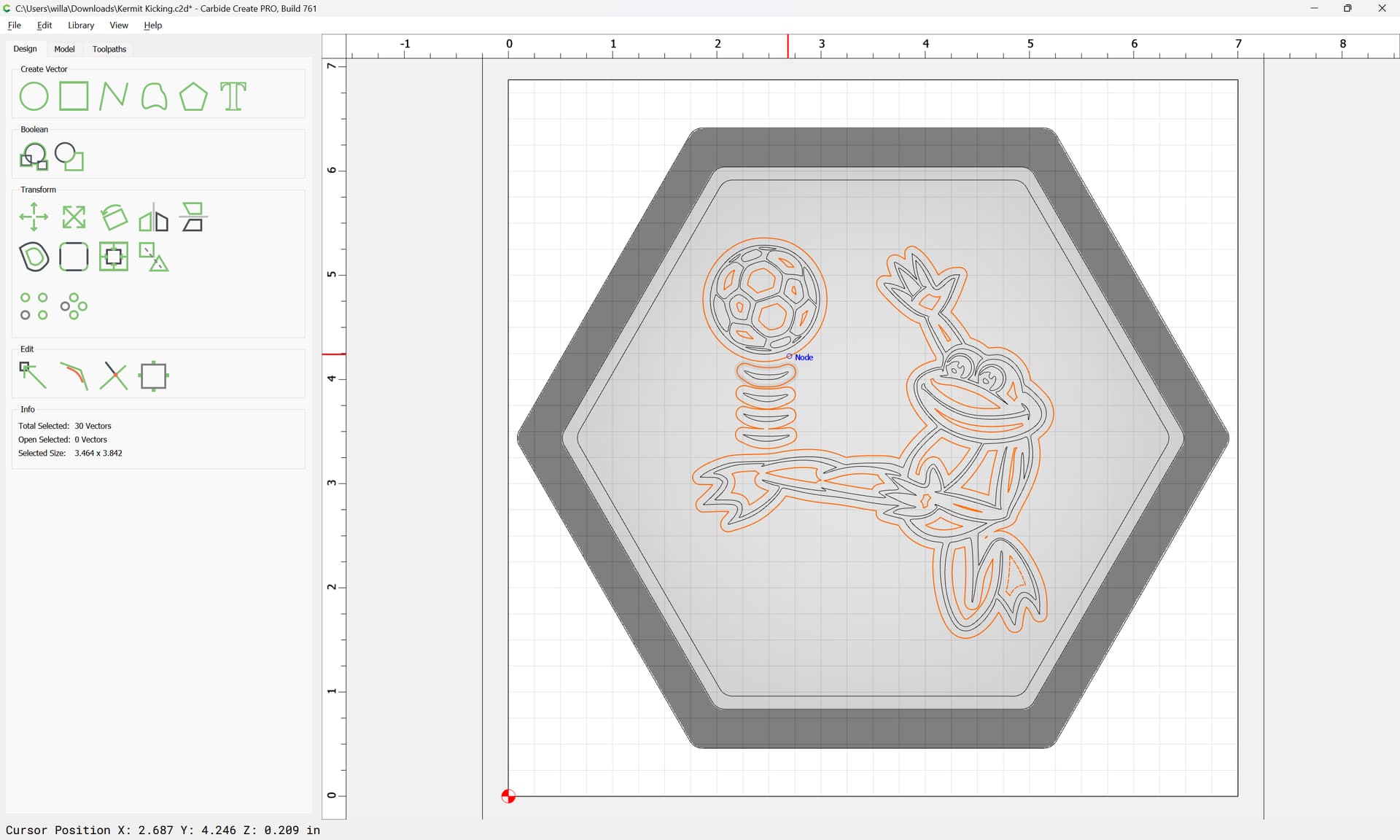
It will be impossible to cut the sharp internal corners, unless we use an Advanced V carving, and such would just collect dust, so we inset by the radius of a ball-nosed tool (we will use a #202):

and then round all of the hexagons off by a bit more than the radius of the tool:

replacing the original vectors

OK

With the design done, on to toolpaths.

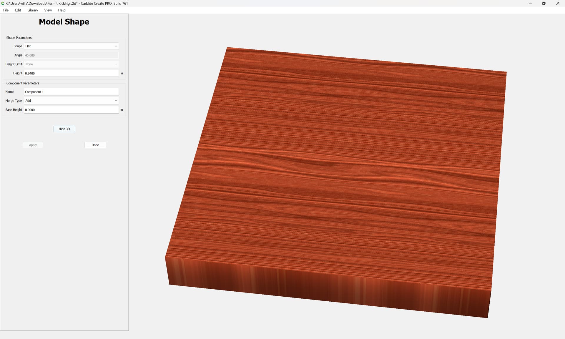
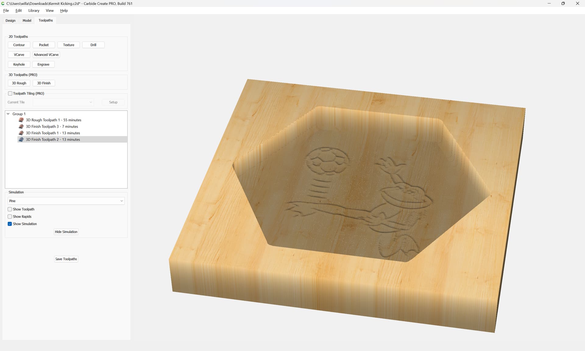
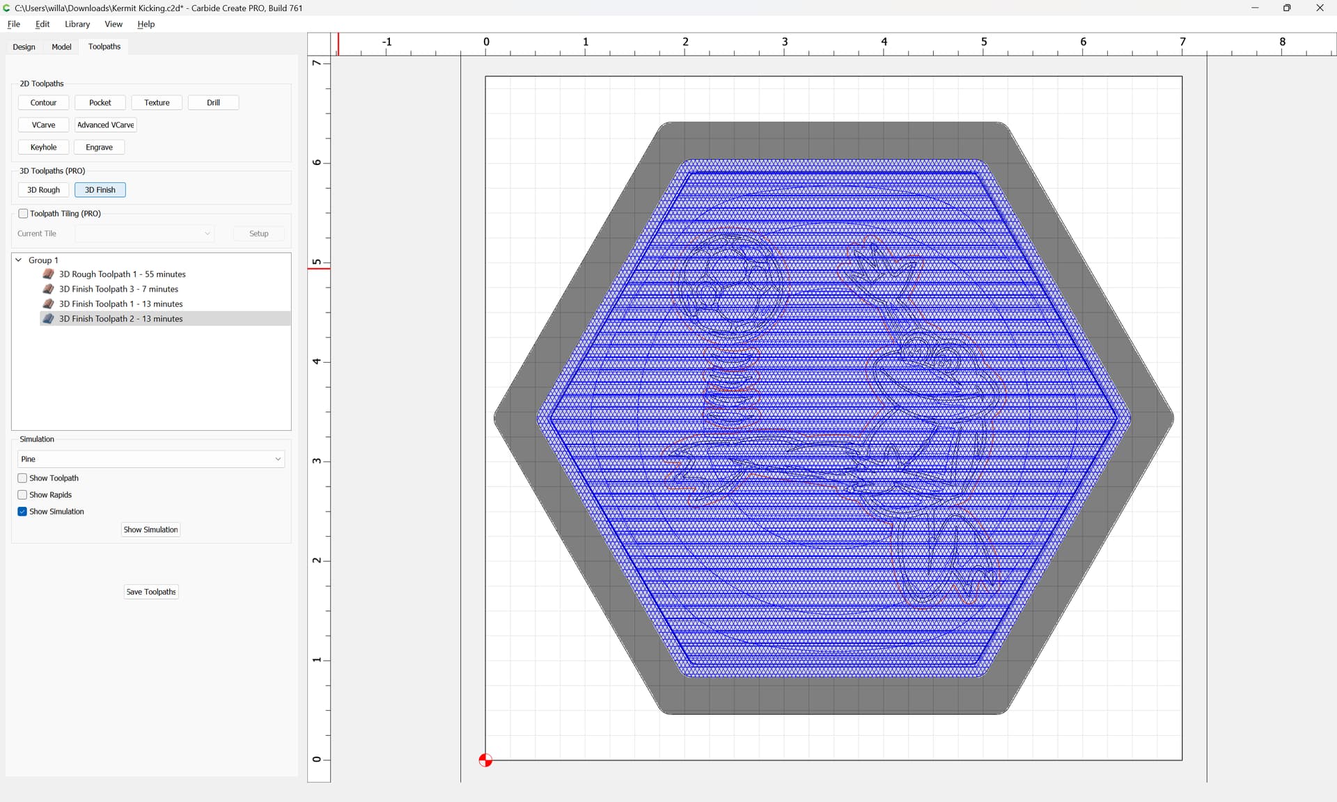
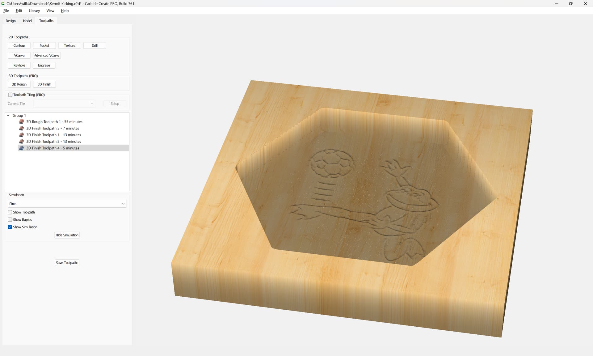
There are two ways to approach the balance of the design — things can be cut in 2.5D, using appropriate toolpaths, or fully modeled in 3D — first, 3D — this will require the stock:

Done

Next, we subtract the internal pocket down to a suitable flat depth:

and then a rounded shape which should still have a reasonably flat bottom:

We then add the design so that it will appear at the bottom:

Apply

Adjust until the design is as desired:

And model cutting out the overall shape — this will require some additional geometry:

and selecting that and the outer geometry:

and then subtracting:

Lastly, 3D toolpaths:

First a 3D roughing toolpath using the geometry for the internal pocket:

Then a 3D finishing toolpath at each angle of the sides:

which one would expect to cut all the sides evenly:

(since they don’t, go back and adjust the stepover as necessary)

Then, a series of smaller 3D finishing toolpaths using smaller tools only around the design:

First, offset around the design by a bit more than the radius of a smaller tool:

Apply

deselect the outer elements:

and delete the inner:

Then, assign further 3D Finishing toolpaths using smaller tools:

iterating until one arrives at a desired level of detail:

2 Likes

This topic was automatically closed 30 days after the last reply. New replies are no longer allowed.