Creating Molds for Leather (form & frame)

Looking for some guidance with Carbide Create Pro. I am new to the pro version and am trying to think through how to create some 2-part molds for a Leathercraft project. Wet-forming leather is a technique used in Leathercraft to mold projects. Leather is saturated with water and is tightly pressed against an object until it dries, creating a custom-molded pocket, sheath or case.

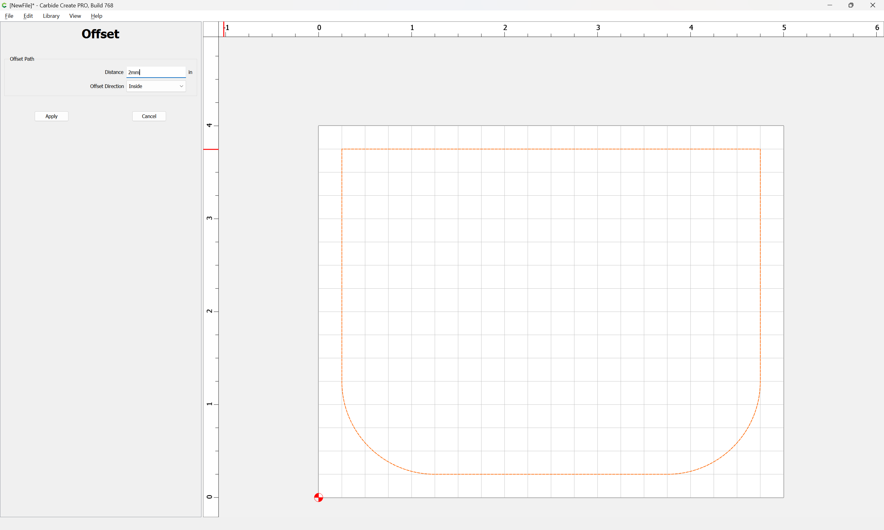
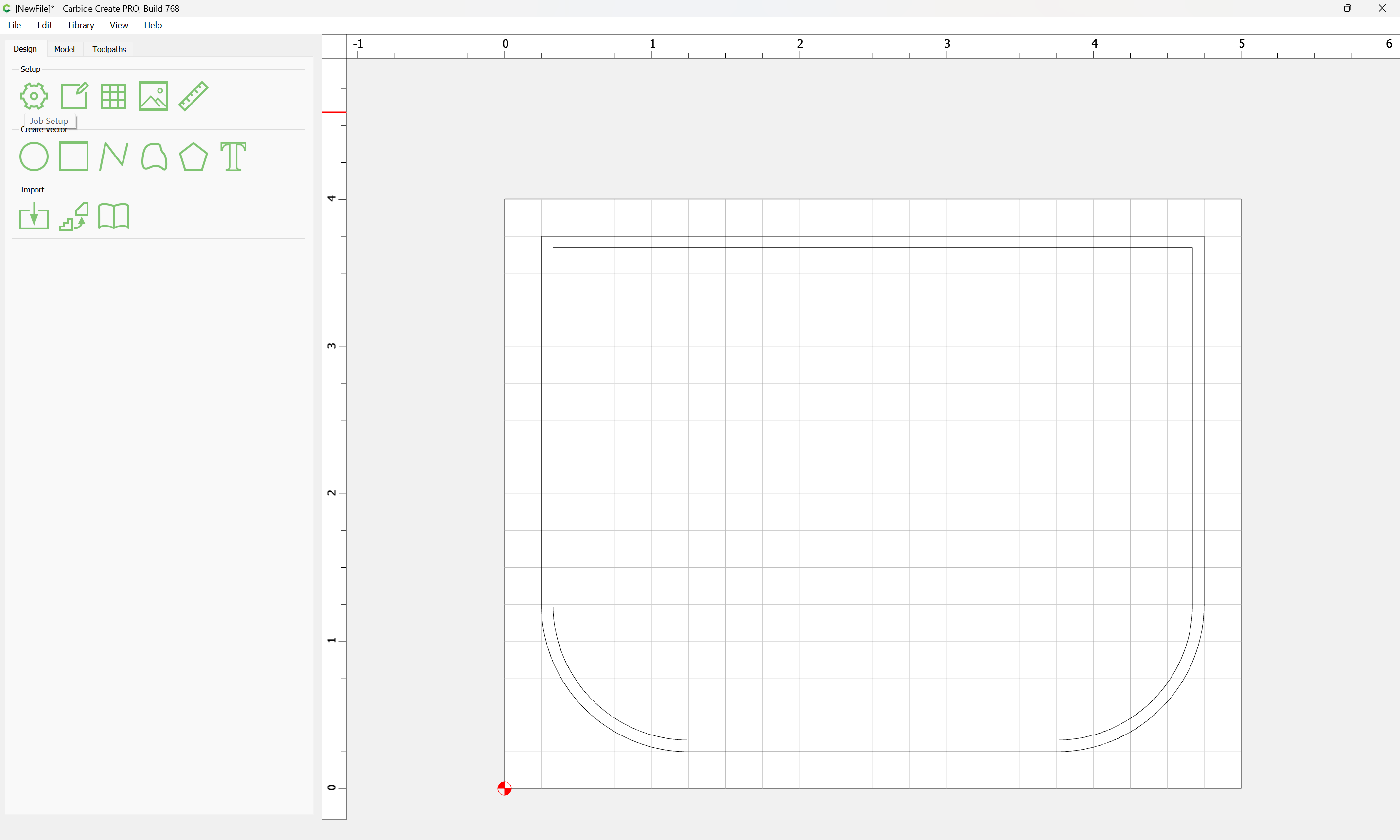
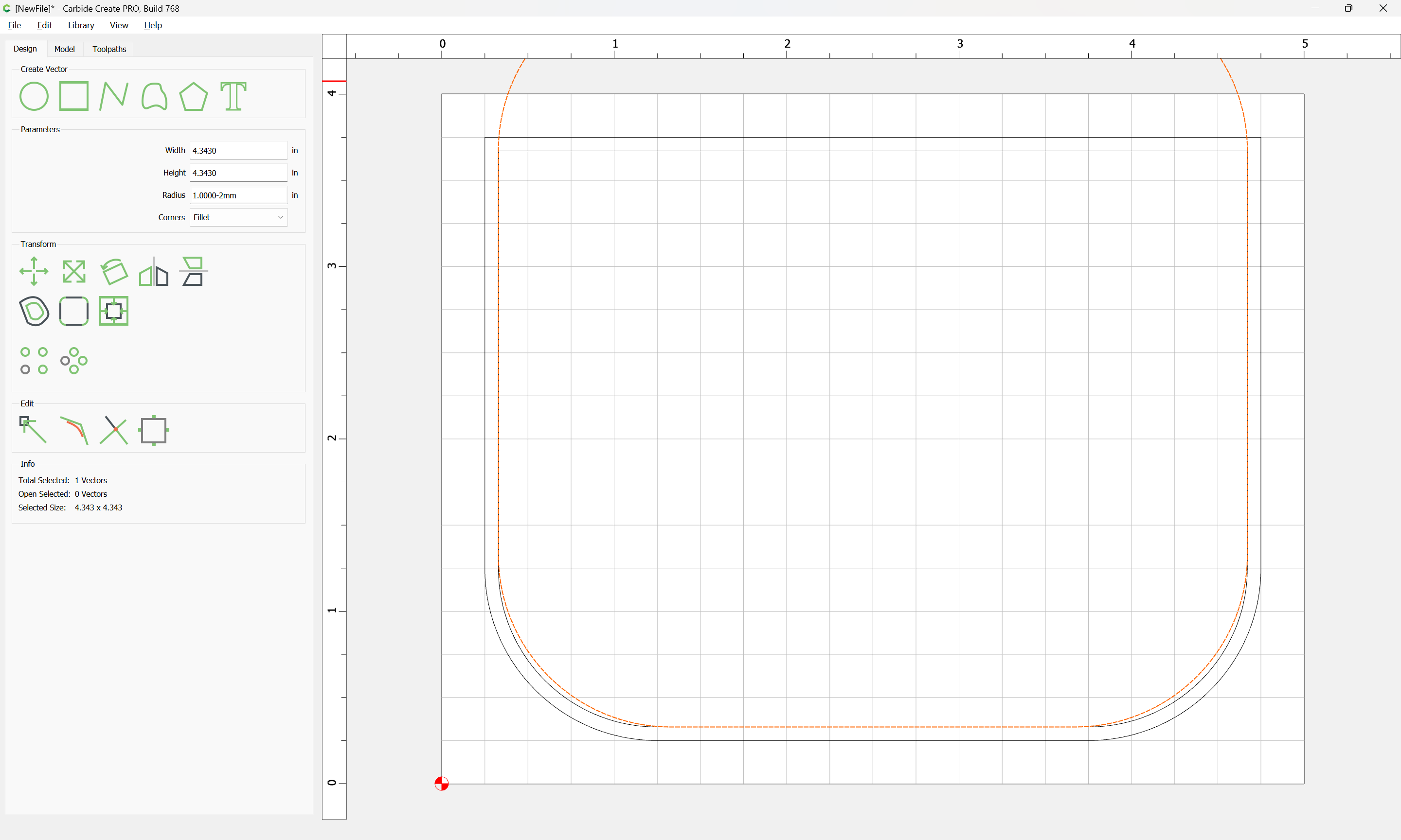
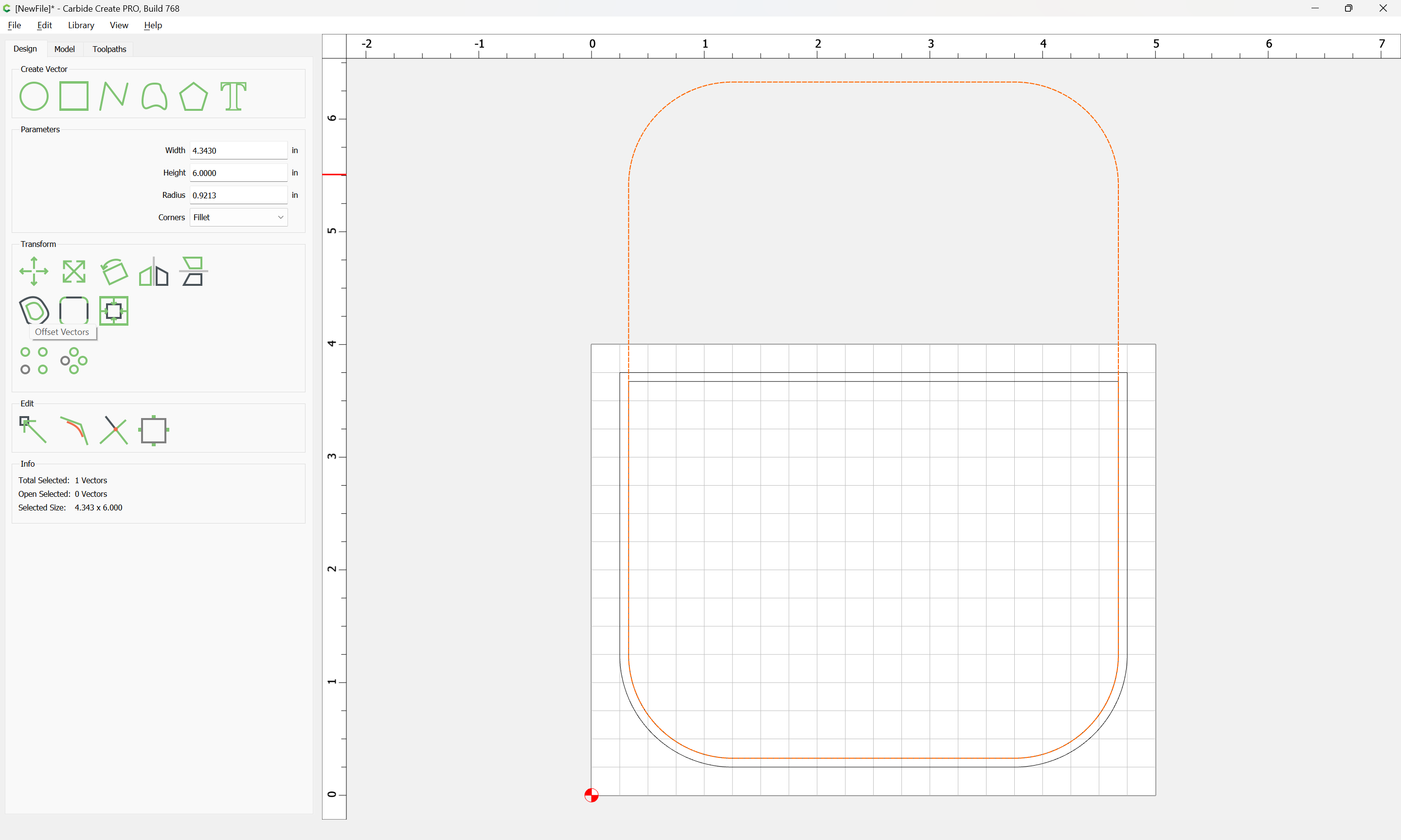
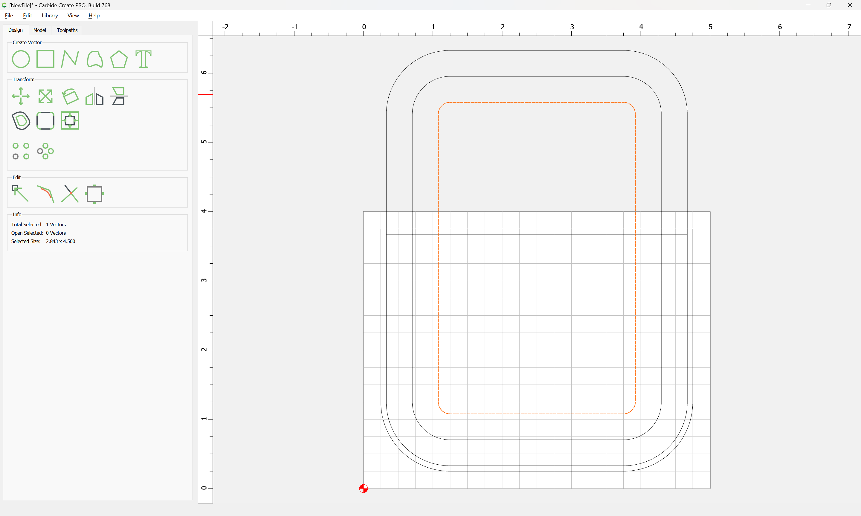
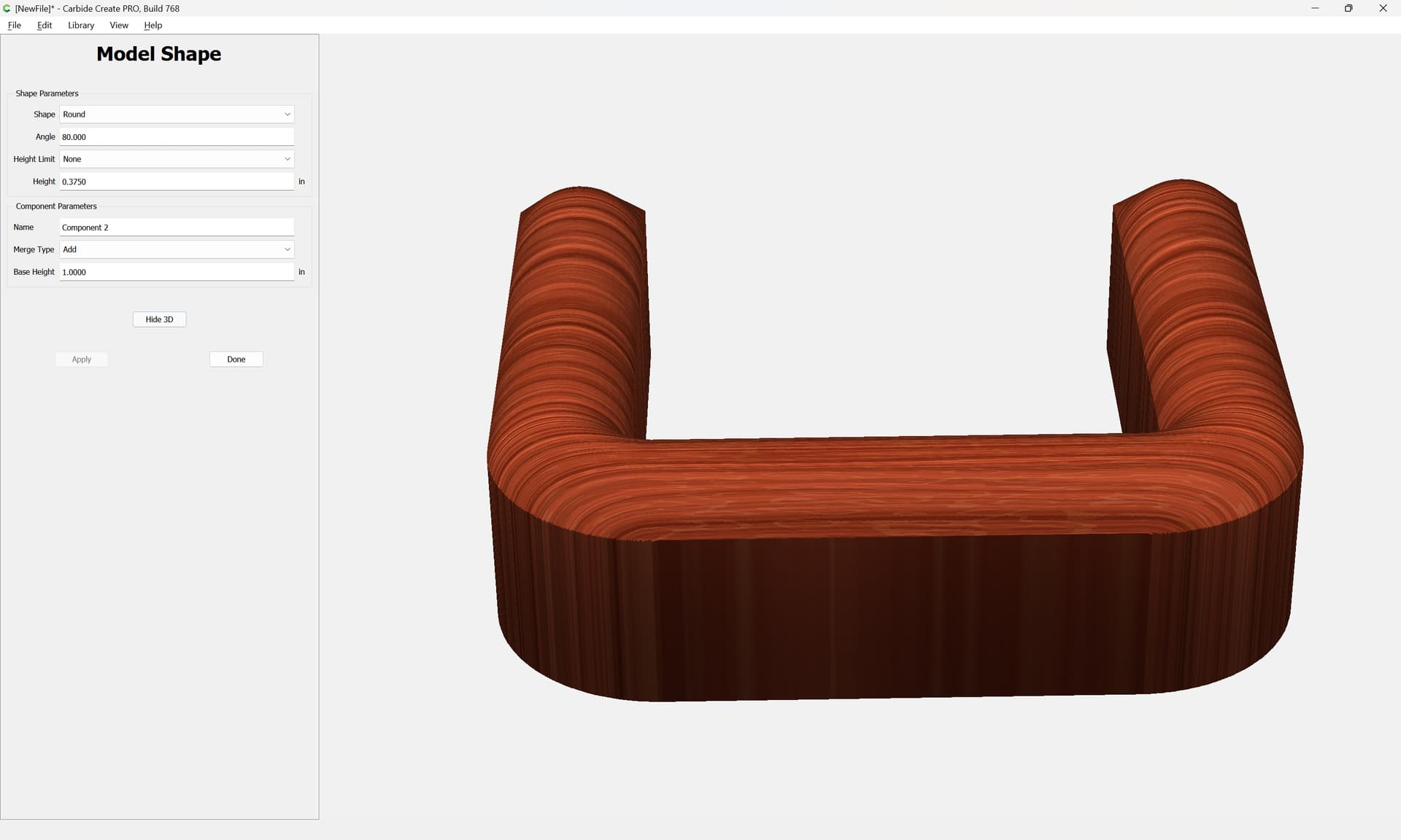
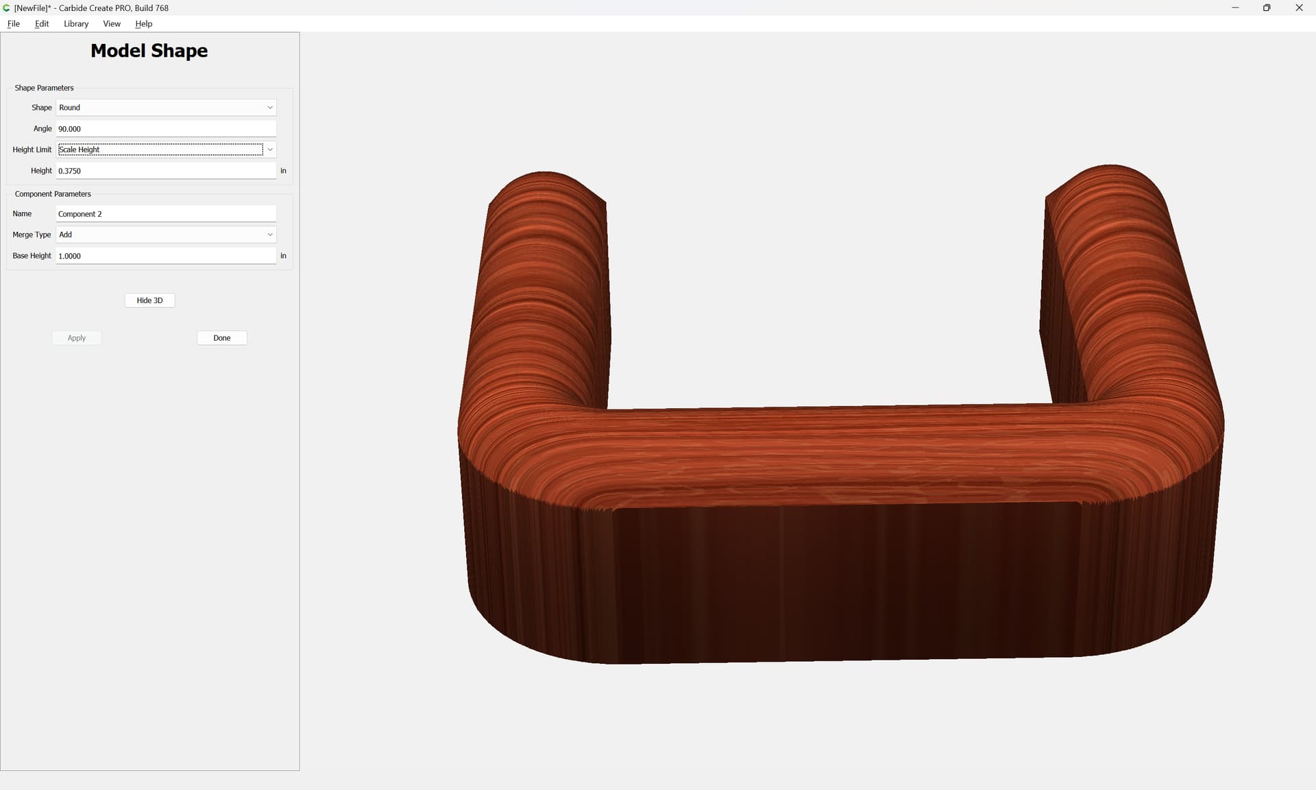
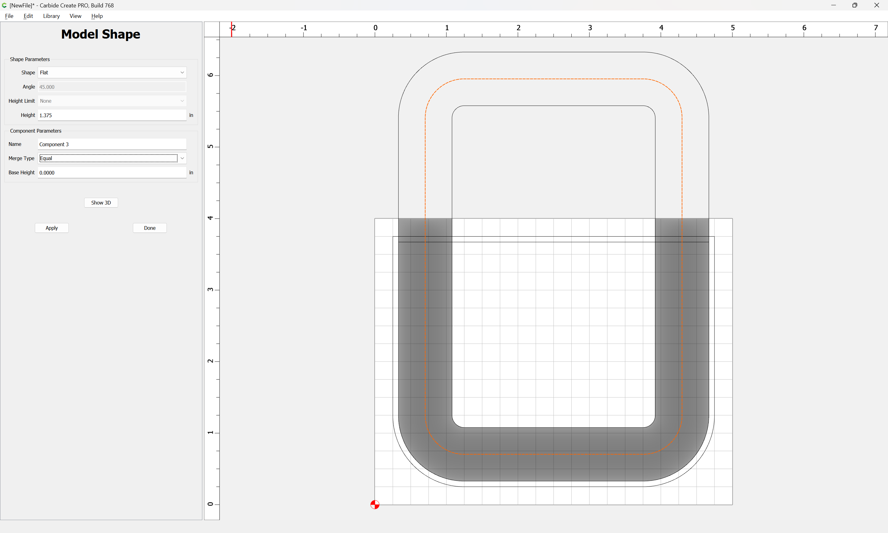
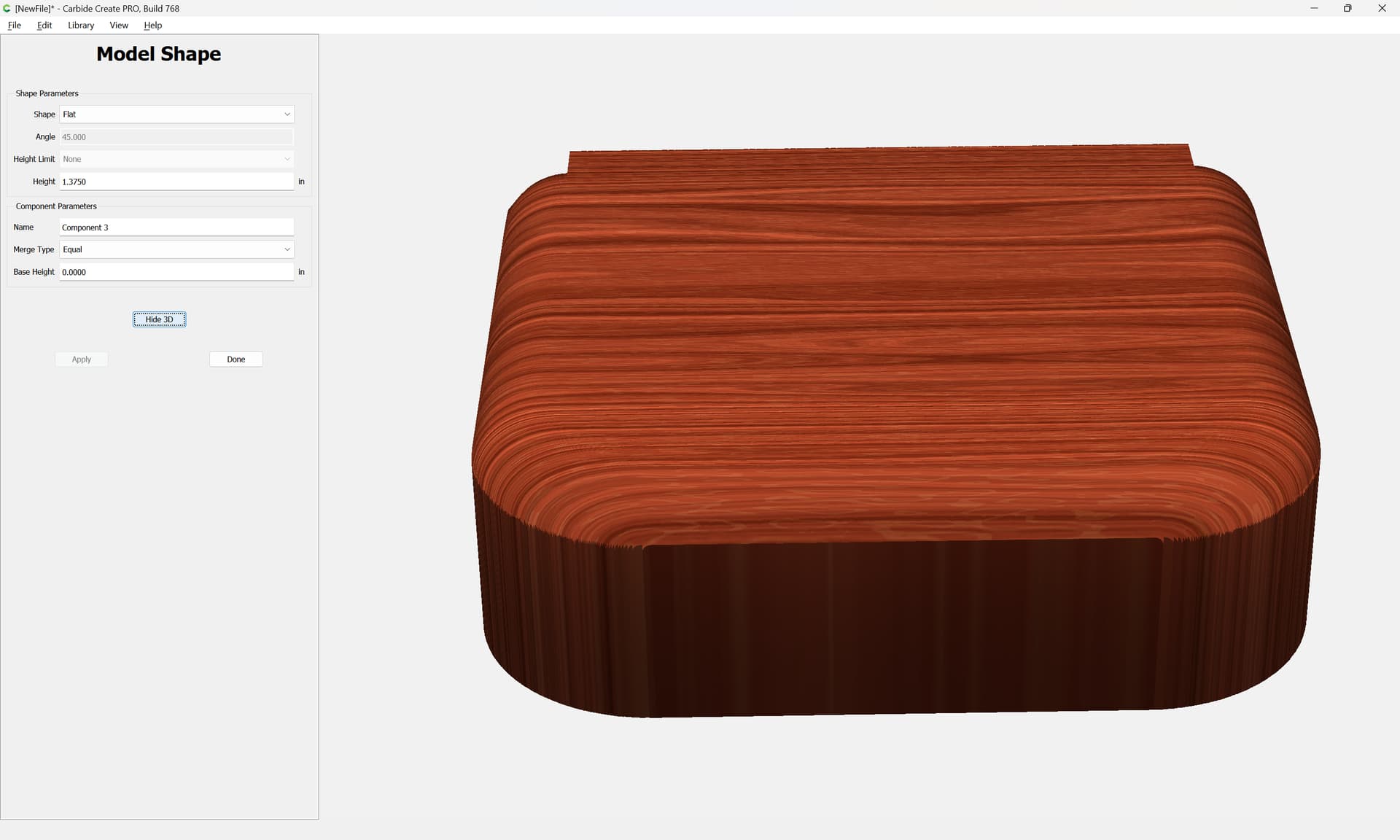
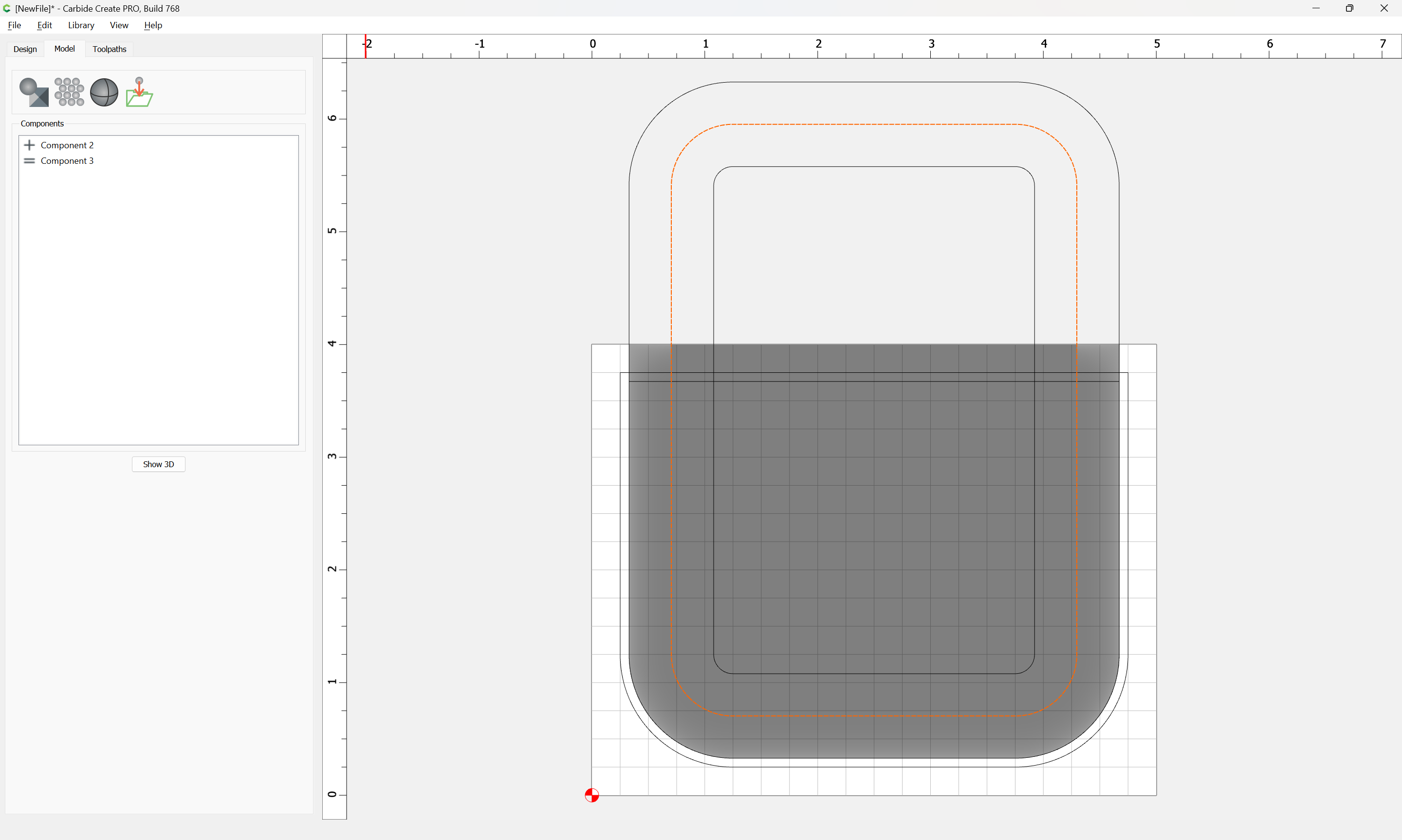
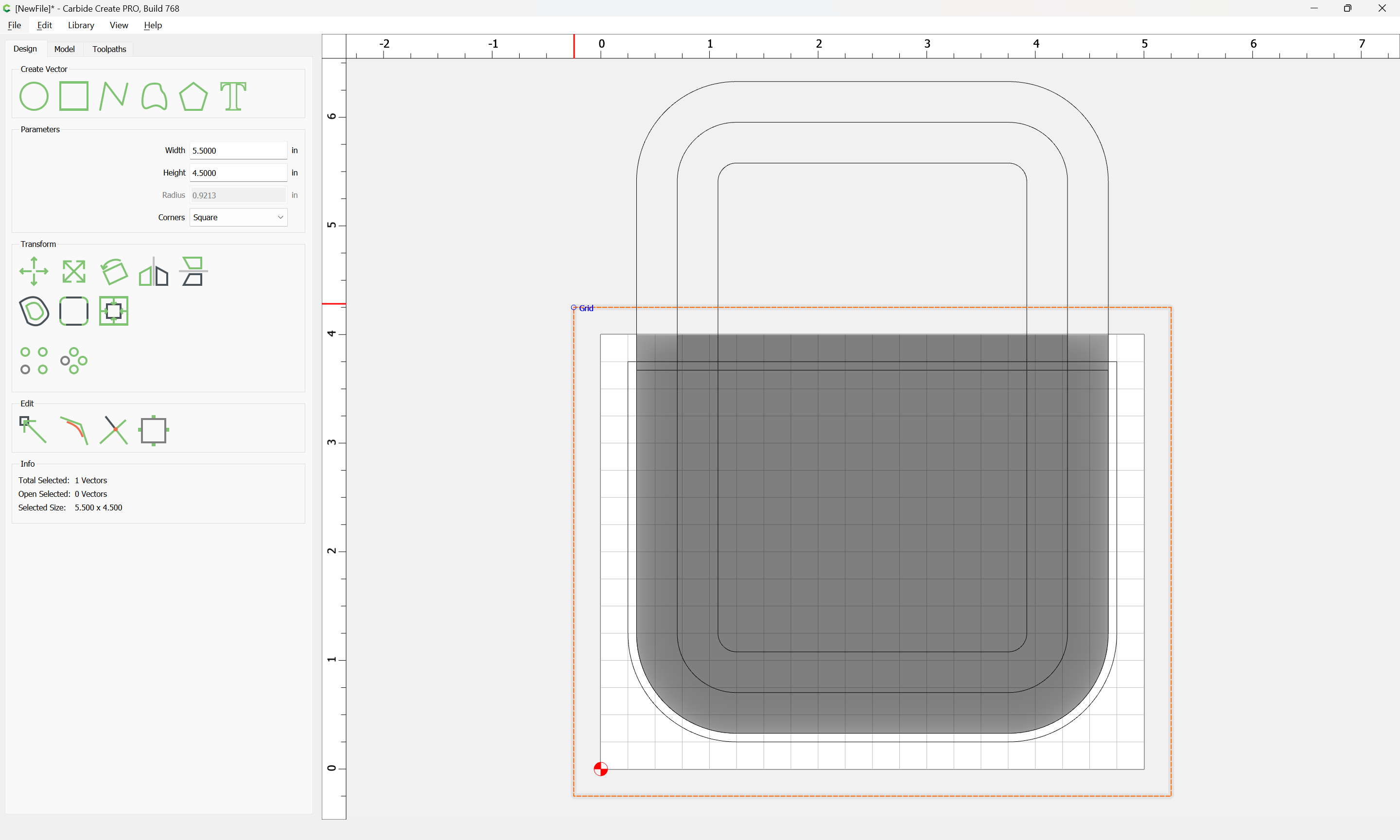
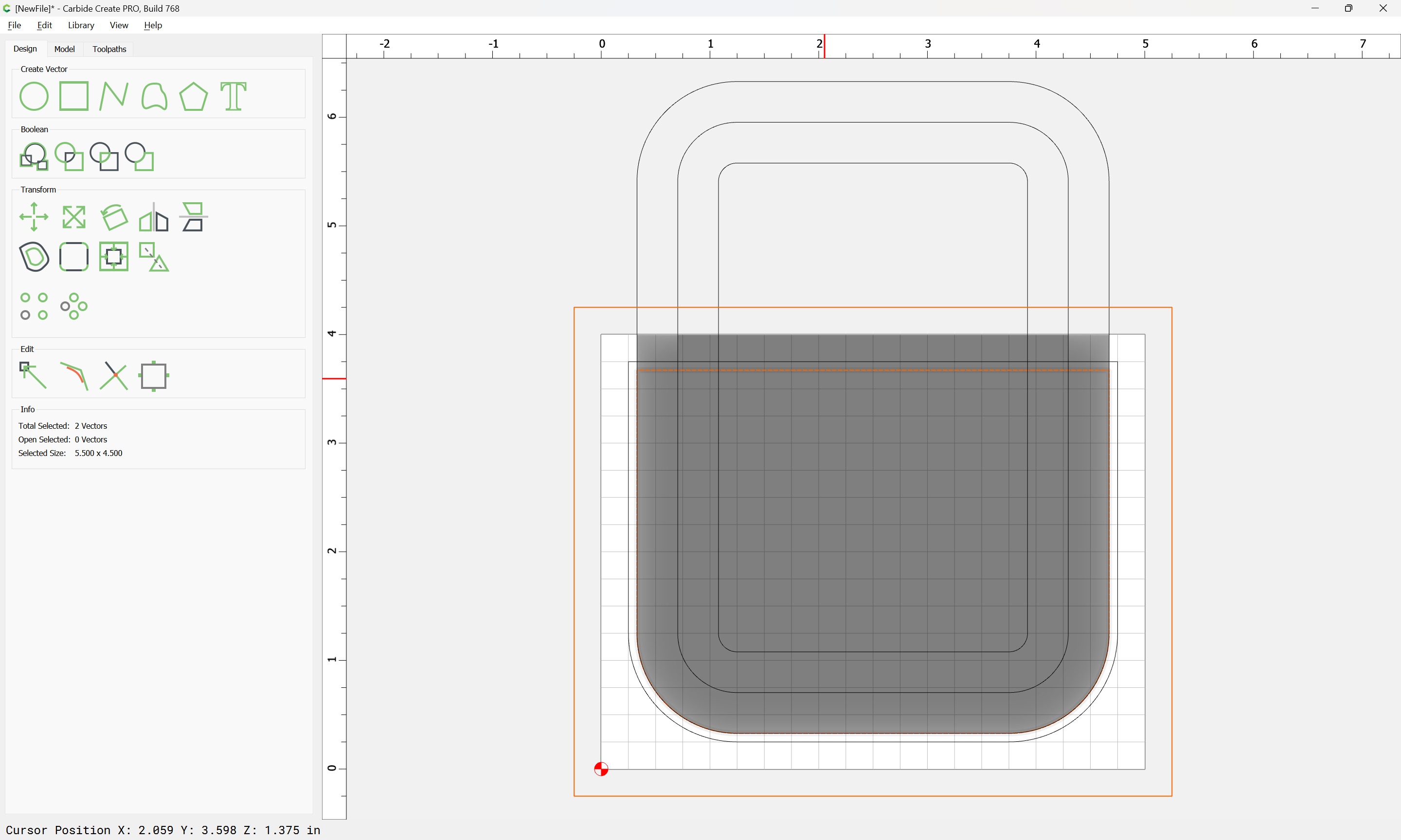
The above is an example of a two part mold–the form and the frame. The frame should be 2mm wider then the form. And the form should have rounded edges. Since I am new to Pro, I am struggling to think through how to model the form.

Additionally, there are other approaches to wet-forming. For example, when making a bowl, you could use a concave form and a convex frame, needing to allow for 2mm separating between the two parts. How would I go about modeling the concave/convex designs so that they mirror each other and compensate for the required spacing?

Really appreciate all the advice.

3 Likes

It should be pretty straight-forward:

Draw the largest version of the shape:

Easiest way to draw this is to draw the rectangle larger than is needed:

Apply the rounding using Filleting:

Draw in geometry to cut the top off square:

Select both elements and use “Trim Vectors”

and click to remove what is not wanted:

OK

OK

and use “Join Vectors” to close things up:

Yes

Use “Offset Vectors” to inset by 2mm

Apply

Then Job Setup for the 3D modeling:

Be sure to set Model Resolution to “Very High” unless that has performance issues.

It will actually be necessary to re-create the larger geometry from before so as to model the straight edge at the top.

There are two options here, a symmetrical form which is consistent, or a more organic shape — we will do the former, and the other, being simpler may be experimented with as desired.

Inset this shape twice, once by the desired amount of rounding, and again by that same amount with the inset geometry:

Apply

Apply

Select the last and first geometry:

and set the parameters to match what is desired:

and if need be, adjust as desired:

Done

Select the middle geometry:

and model it to the thickness of the previous component:

Done

Draw in geometry larger than the Stock:

Select it and the desired shape:

and model so as to remove what is not wanted:

It will then be necessary to set up toolpaths so as to cut things out — this will require “long-reach” tooling which Carbide 3D does not sell.

Really appreciate the reply, Will. Would you mind discussing the toolpathing for wood that is 1" thick?

I realize that I left out an important detail–creating a thick form in two pieces with the other piece being just a simple contour cut of the shape.

Then I would clue the two halves together before mounting to a third board larger than the form. Finally, I would create the “frame” with simple contour cuts.

You will need to purchase “long reach” tooling, or set up the job as a two-sided/flip job:

The frame and other parts should be straight-forward, see:

https://my.carbide3d.com/gswso/11/

You can use the same geometry/model. Just cut the top half using the 3D shape 1" deep.
Then program a 2D pocket/contour using the vector, again 1" deep.
Finally, use the offset/larger curve to contour the inside of the frame.

As for the bowl example, I find it easiest to draw it up as a section/side view & just measure to get dimensions.

Transfer the offset side down to the plan view to draw the offset circle. Now the larger circle gets modeled as a round, “Scale Height” to whatever height you want the bowl, and subtract.
The smaller circle gets modeled the same, except using “Add” as a merge type.
Use the subtracted component to program the path for the female side, and the added component to program for the male side.

1 Like