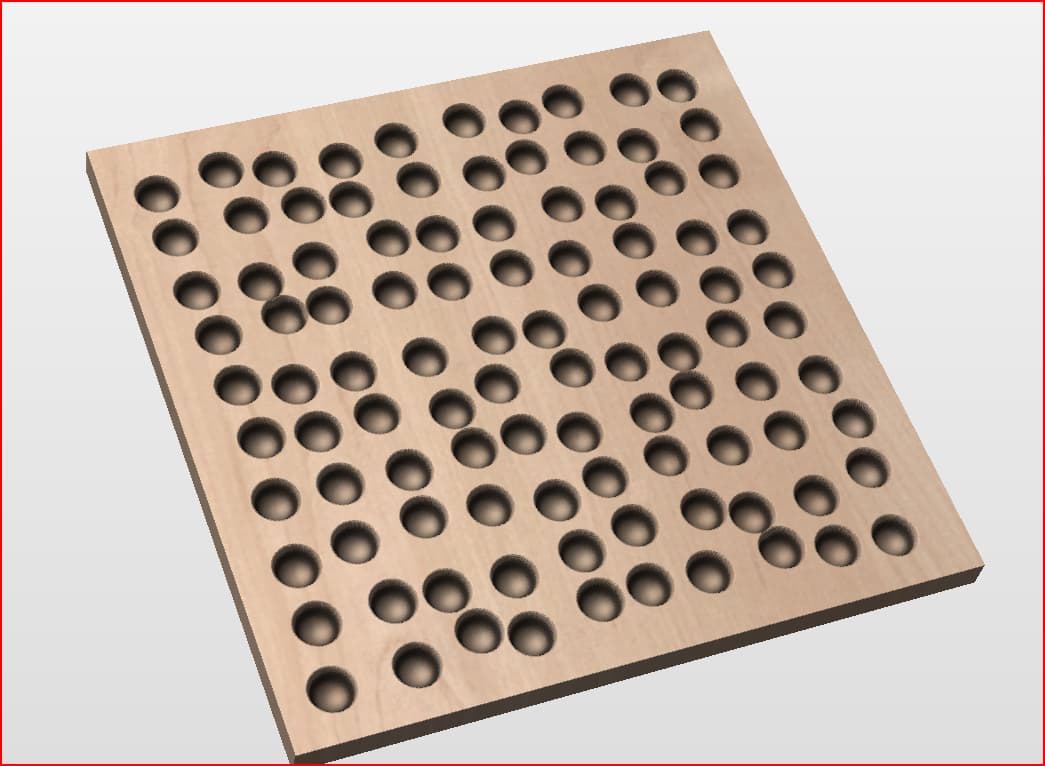
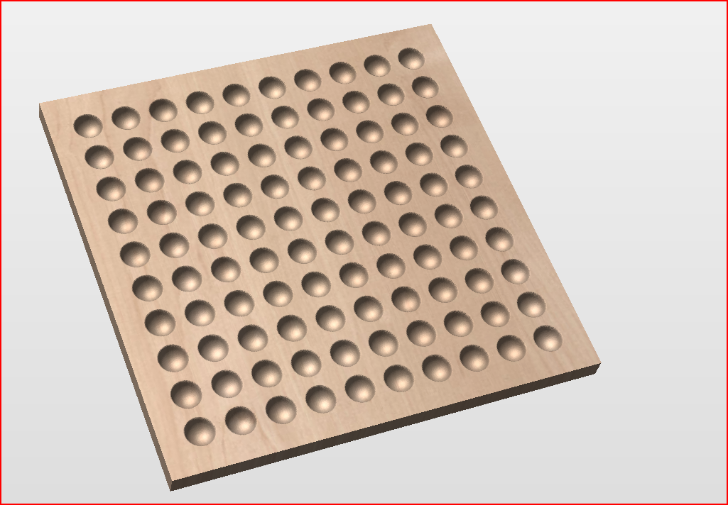
I’m looking to create a series of textured surface patterns on hardwood using my Shapeoko Pro 5. Specifically, I want to mill small, concave, crater-like divots (roughly the size of a pea) across a surface, and I’d love guidance on how to approach this—especially starting with the first project.
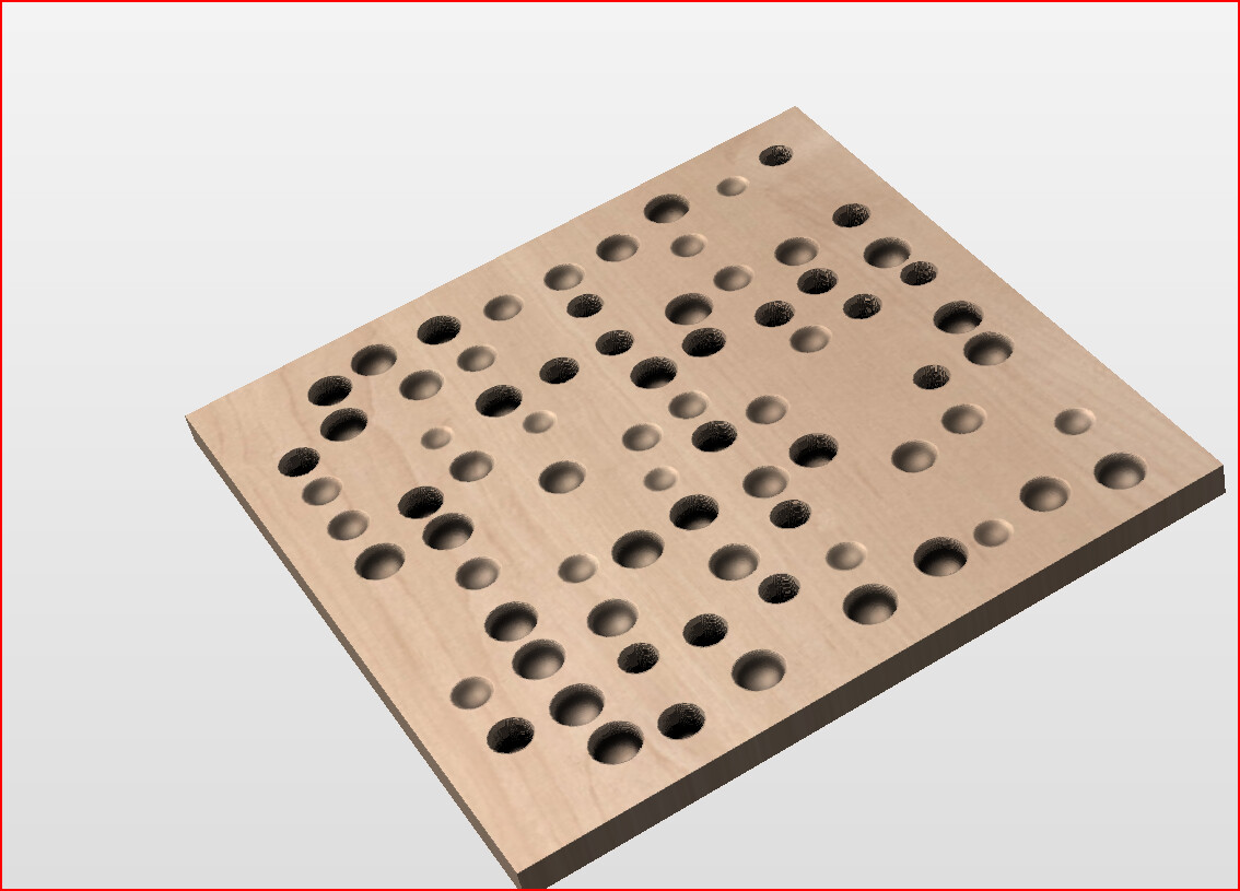
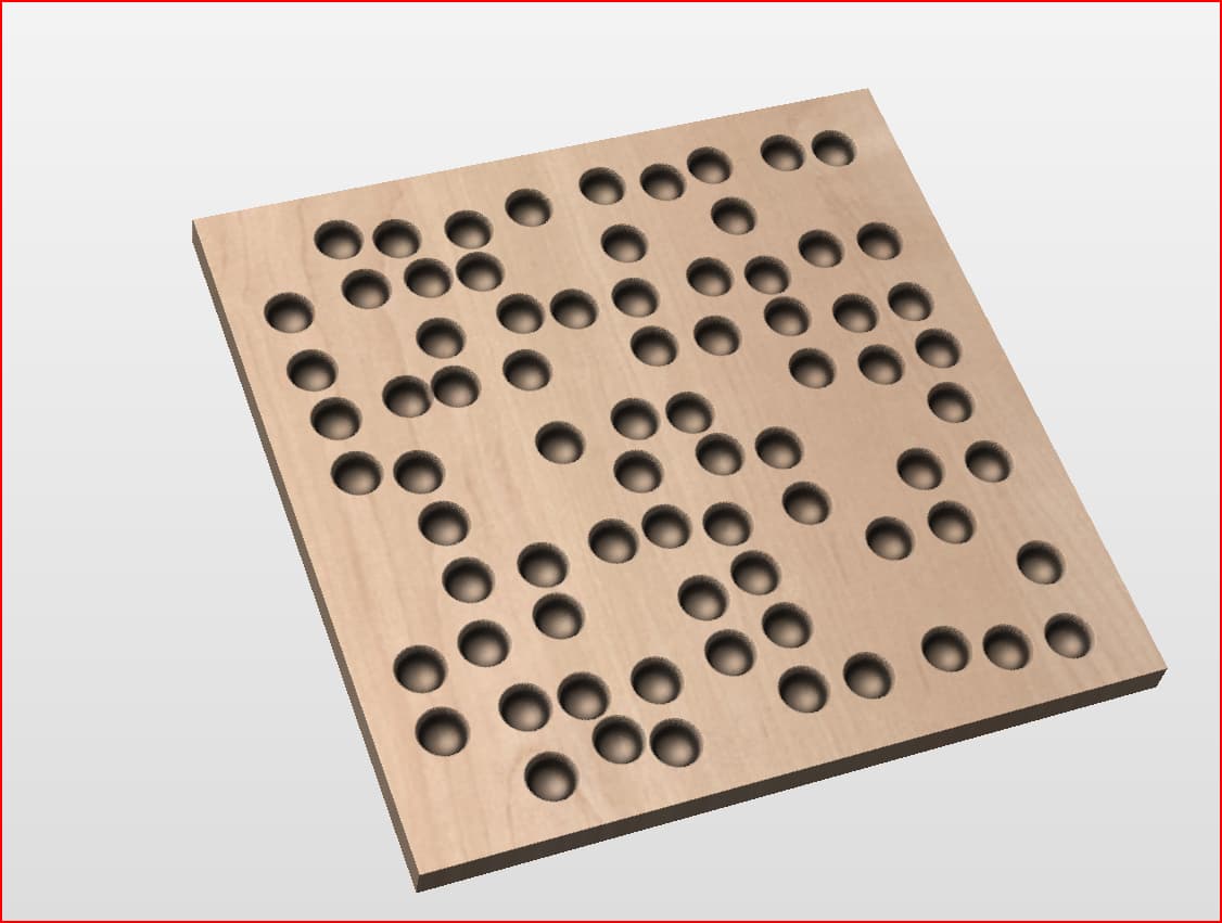
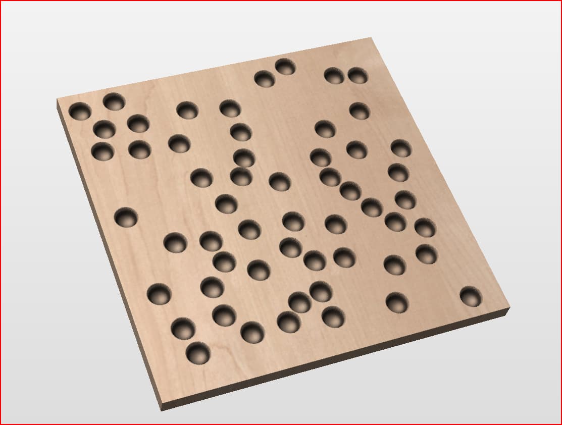
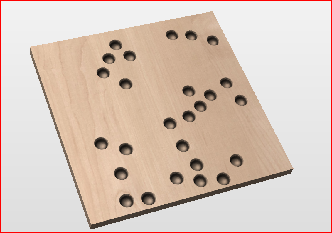
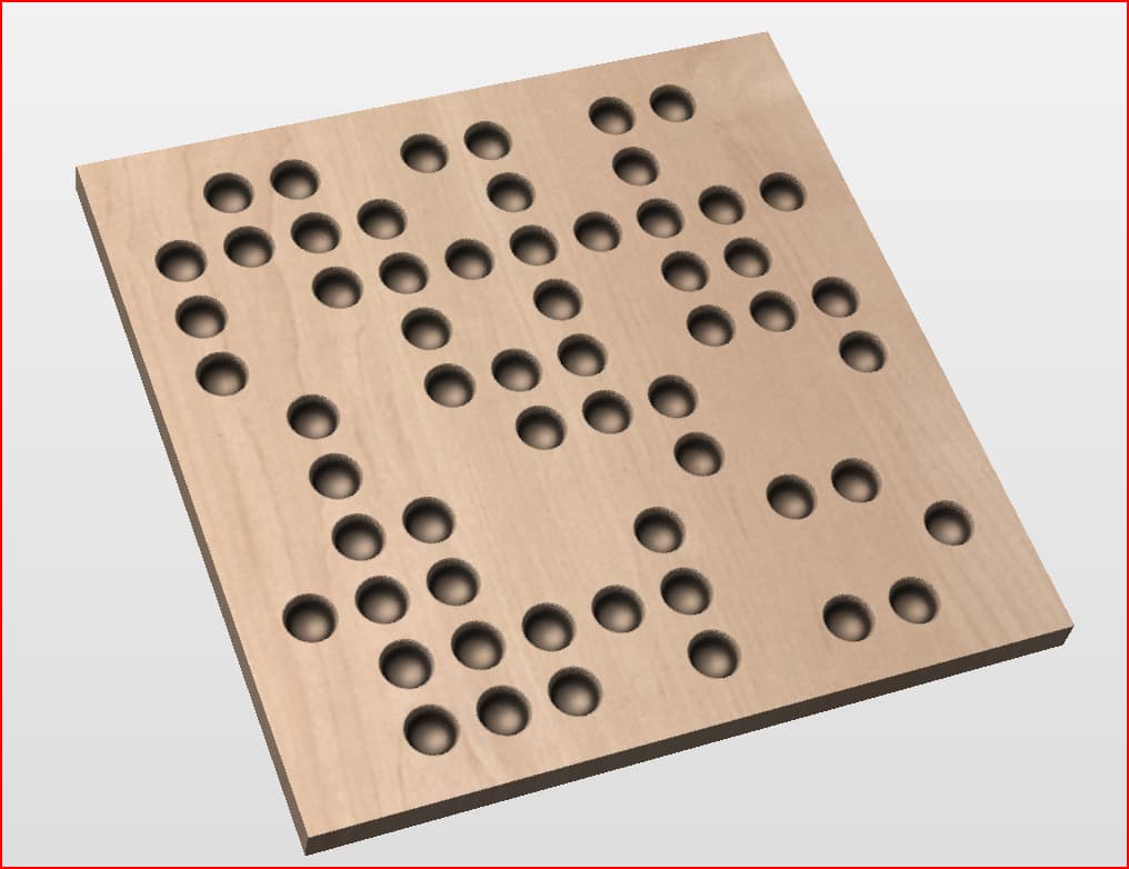
Project 2: Same as Project 1, but with randomized spacing for a more organic, natural feel.
Project 3: Same as Project 2, but with varying depths for each divot to add texture variation.
Project 4: Same as Project 3, but with tapered ramps (e.g., 25° angle) into each cavity instead of a direct plunge.
Even just a walkthrough or technique to accomplish Project 1 would be a huge help.
I’m comfortable using carbide create software and running toolpaths, as well as Shapr3d although I’m a novice, but I’m unsure how to generate or automate this kind of pattern—especially with randomness or varied depths.
Any advice on software tools, toolpaths, and design techniques would be appreciated!
We know the tools we know, so if I were faced with this design challenge, I would approach it in the following way (I enjoy design challenges). @WillAdams is Mr “Carbide Create”.
I use F360 or VCarve Pro for CAD and then CAM output, but similar functions are available in Carbide Create. However, CAD packages generally don’t offer “random” functions, but they can be coded with plugins - but that’s not what I do.
CAD/CAM “Drill/Pocket” approach: If you have a ballnose bit that is “pea-sized,” the CAD/CAM package can be used to drill or pocket holes and making the CAM think it has a flat bit that is pea sized in diameter. Pockets or drilling points would have to be set, either fixed or randomly, by hand. Then, peck or drill away using the ball-nosed bit.
3D Relief Carve using a ball-nosed bit smaller than the diameter of a pea, using an imported OBJ/STL (3D object) or greyscale height field map of the surface modelled in a suitable 3D modelling package of your choice. I use Blender and Houdini for modelling.
I created the following obj/heightfield maps in a few moments, 100x100 mm grid, 3.175 mm hole, minimum spacing between holes of 2 mm: