WillAdams
March 14, 2024, 12:46am
1
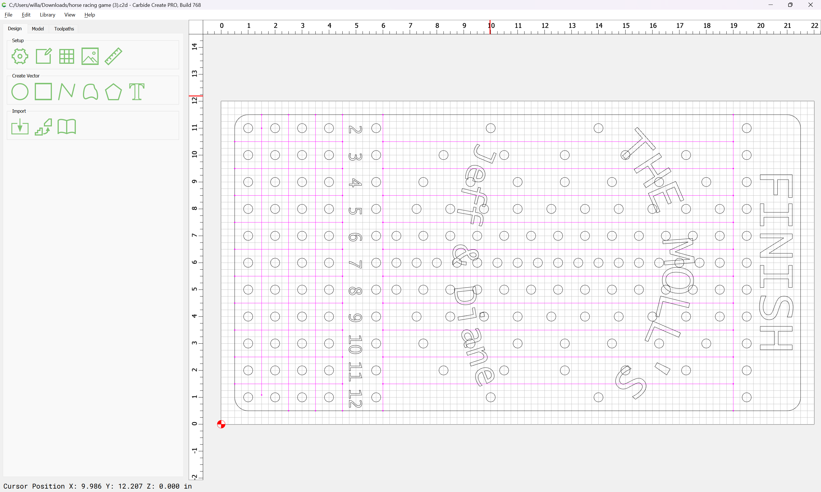
Given a file:
Which one wants to have closed geometry for making toolpaths, one possible way to do this would be to:
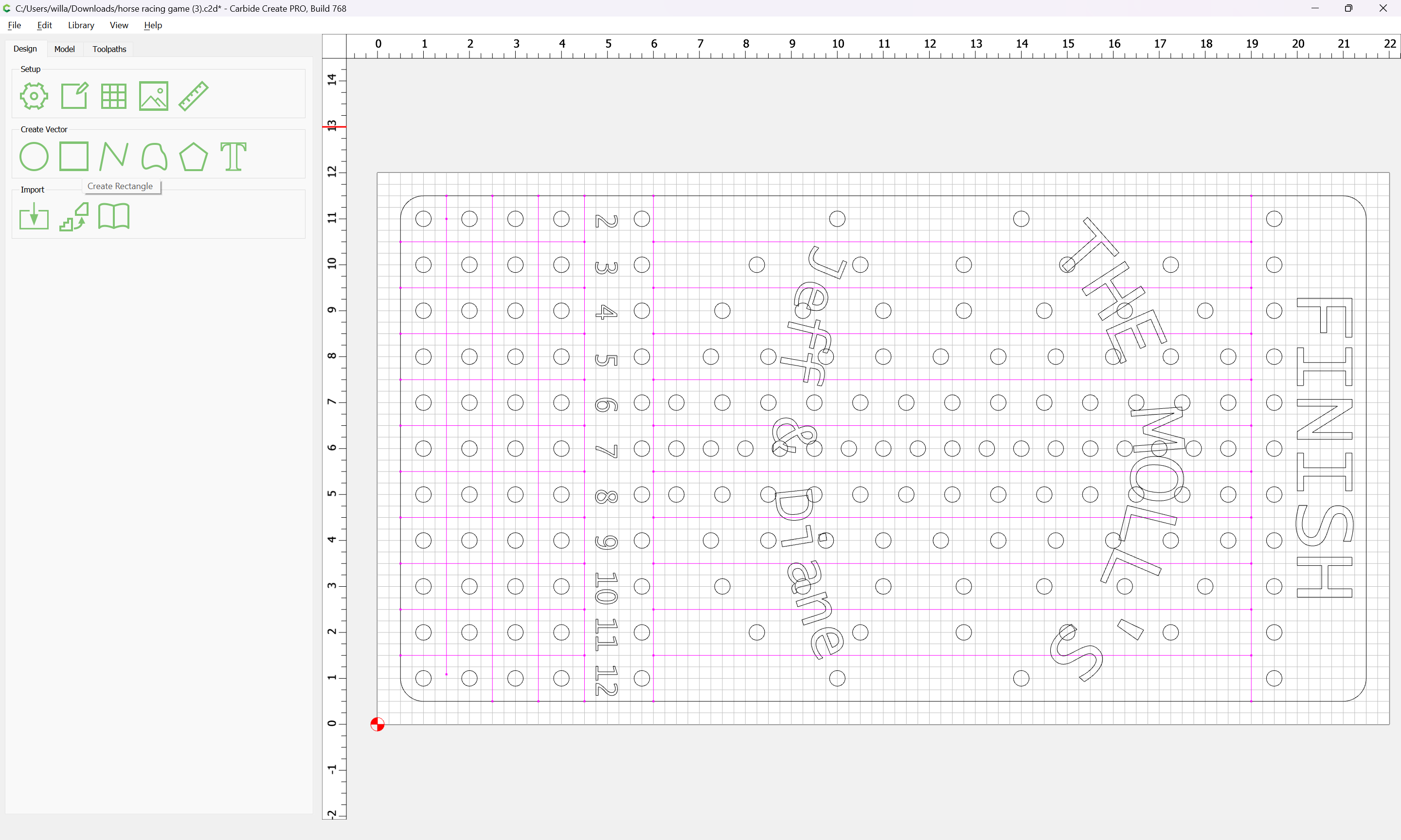
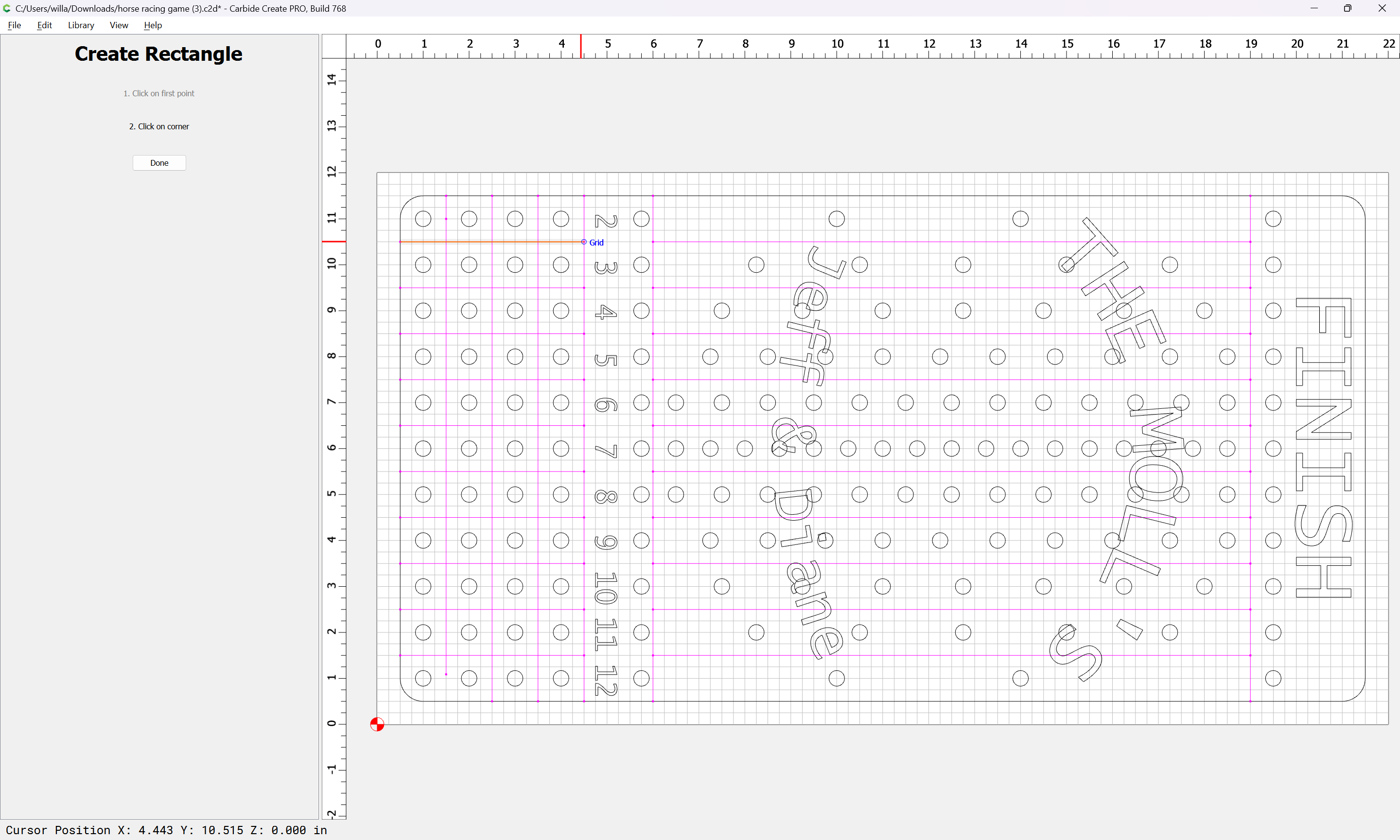
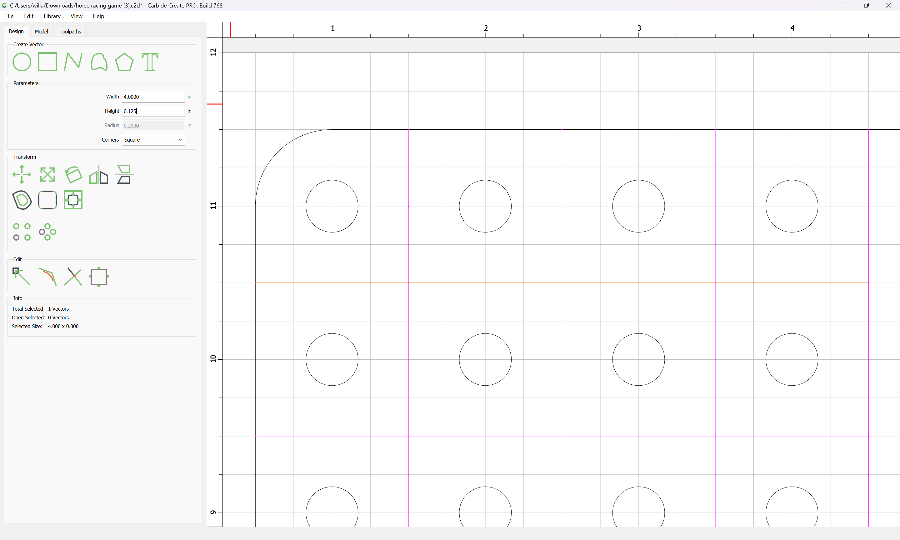
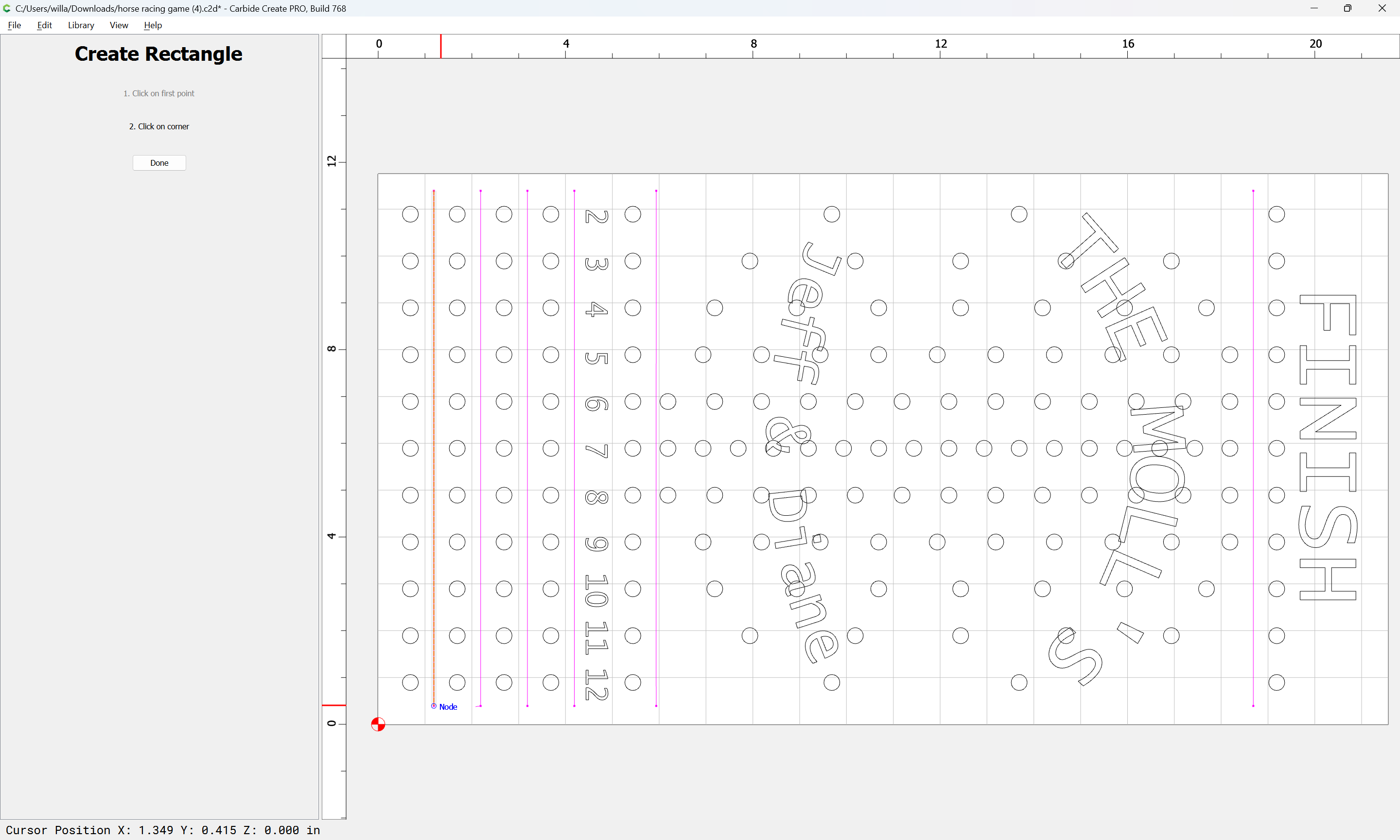
Use the “Create Rectangle” tool to draw in zero height/width rectangles:
while holding down the control (command key on a Mac):
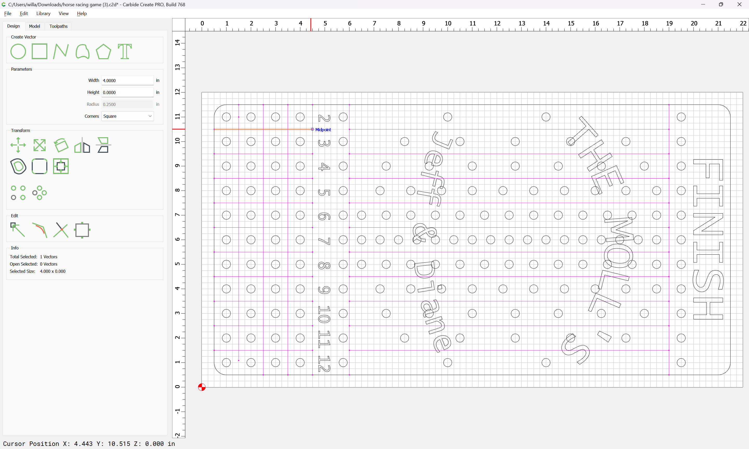
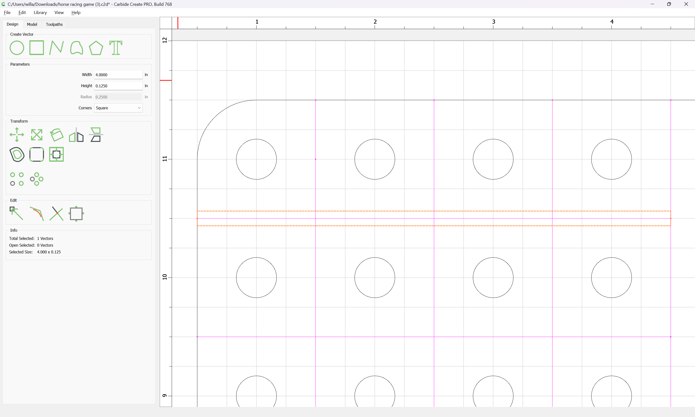
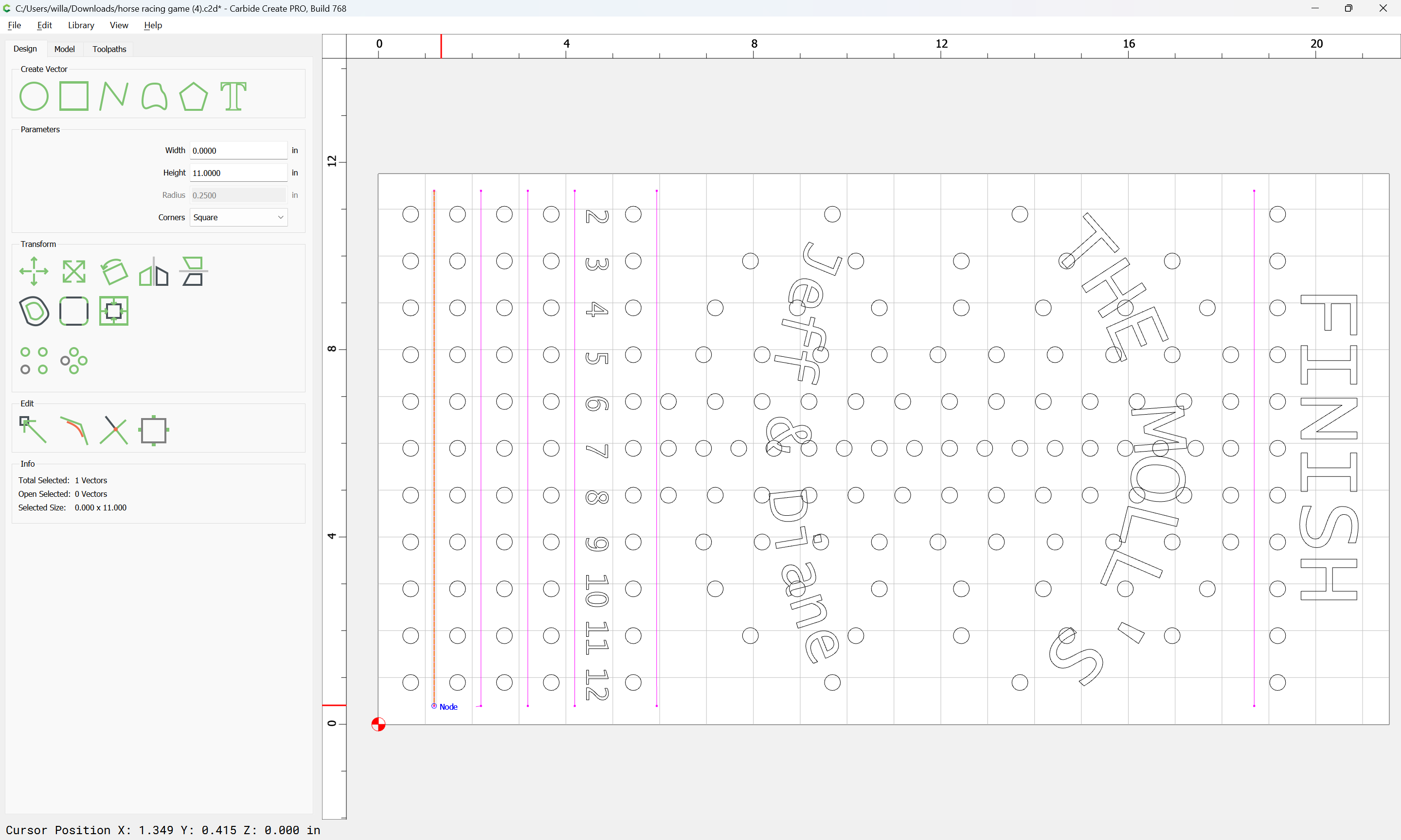
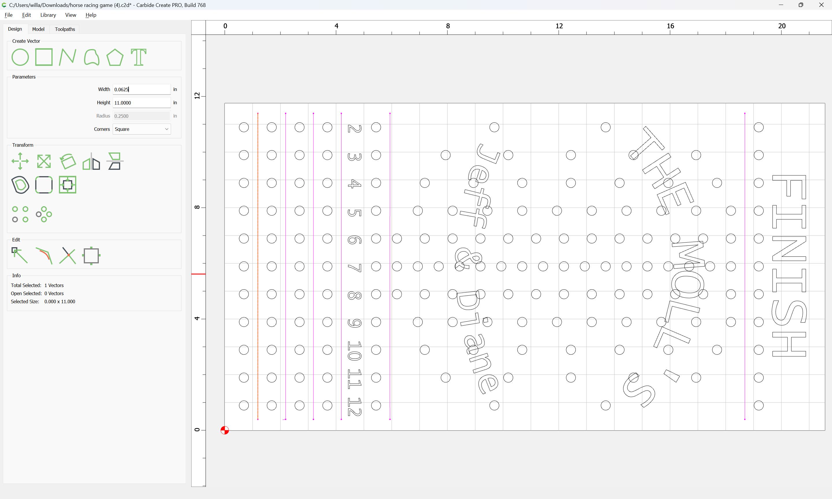
to get rectangles which when the zero dimension is increased to the desired dimension:
are the correct dimension.
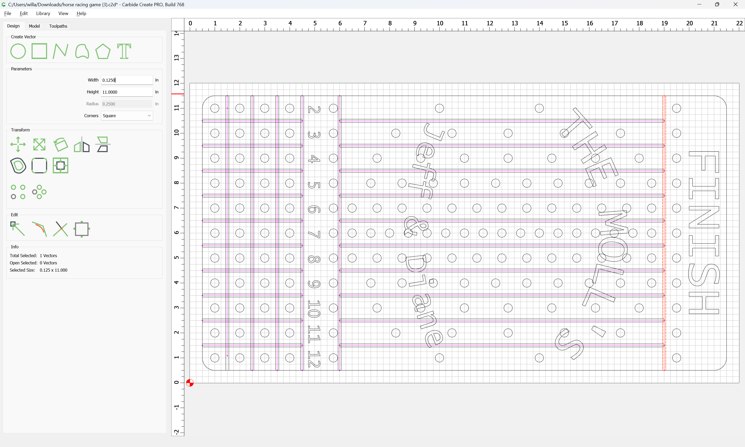
Draw in all such geometry:
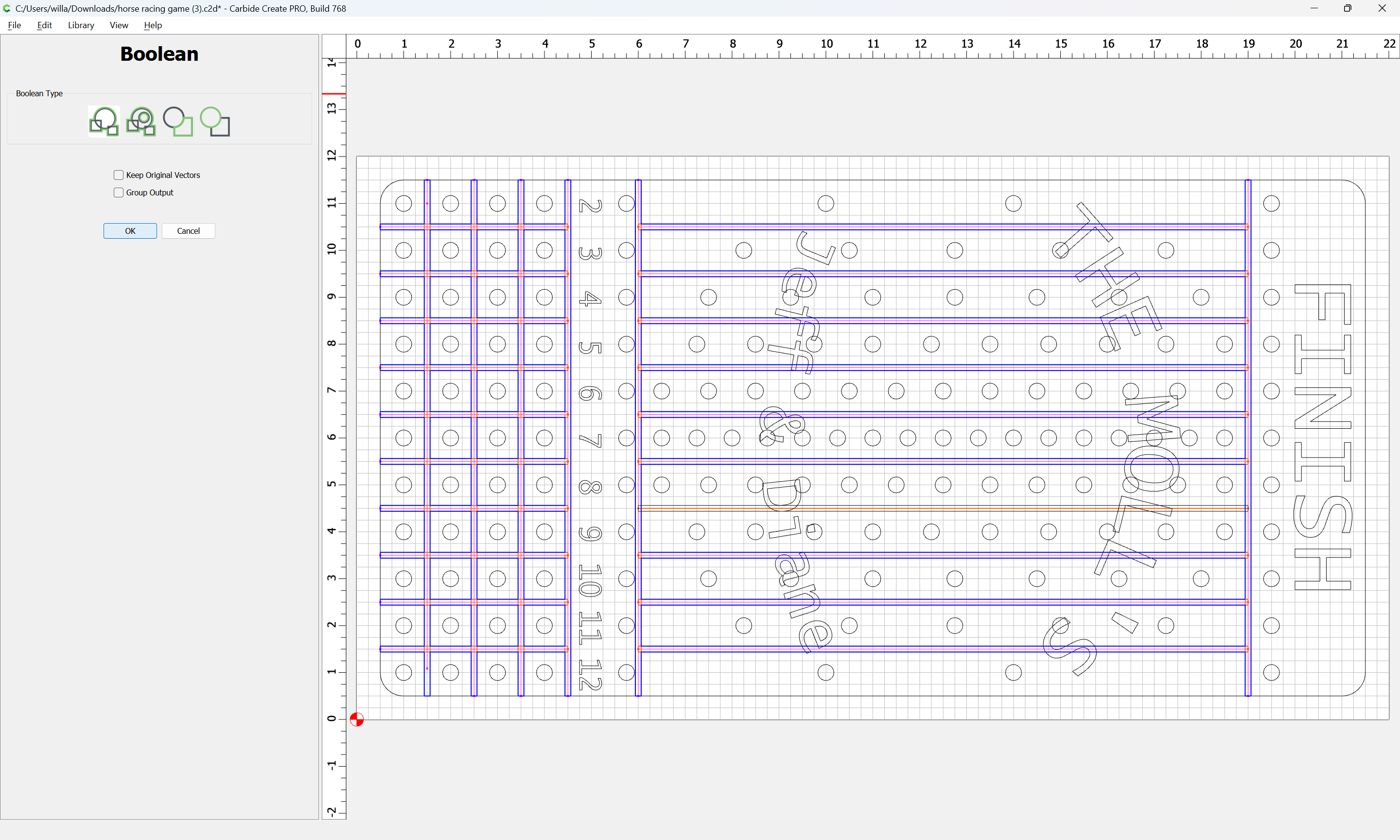
Then select it all
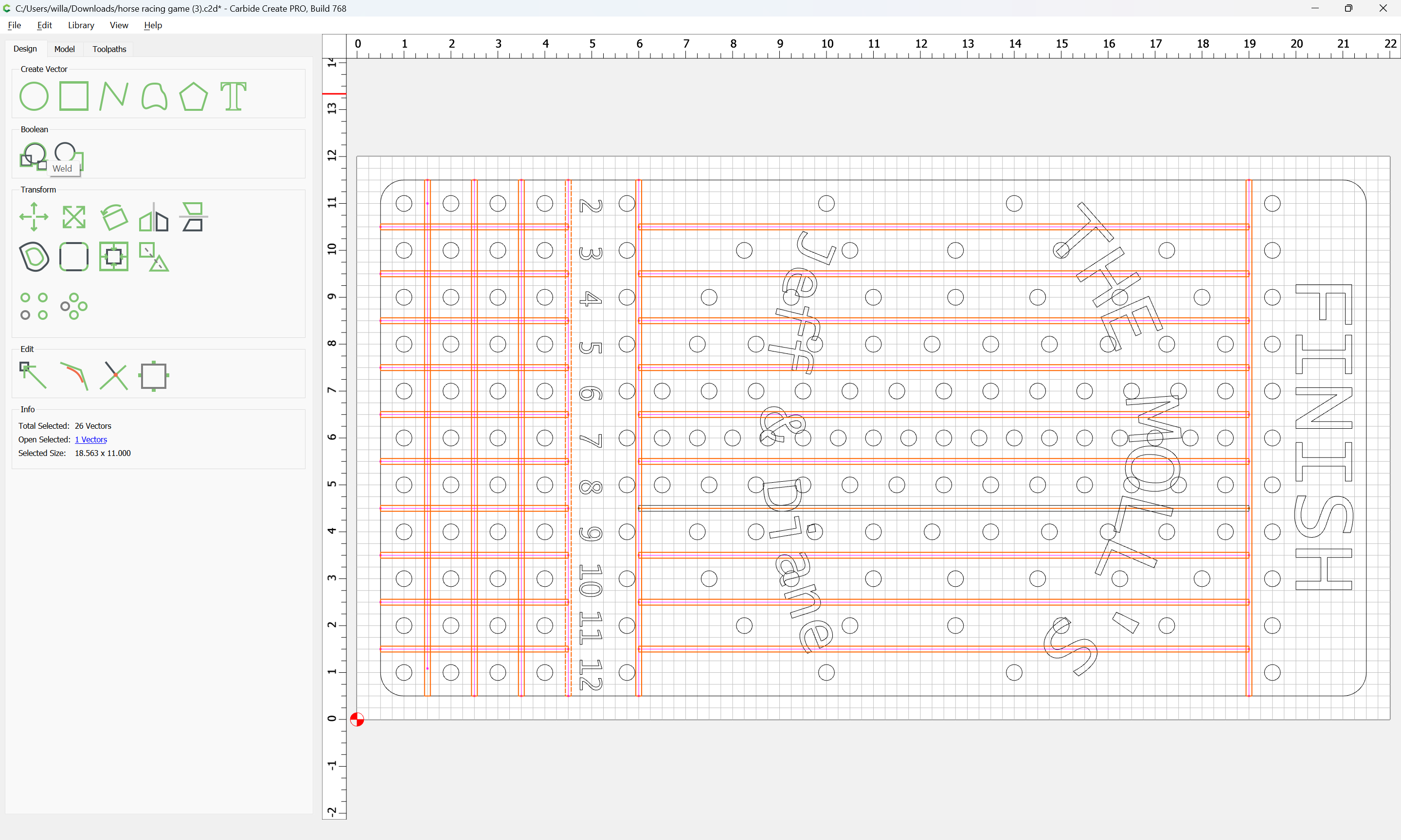
and do Boolean Union:
OK
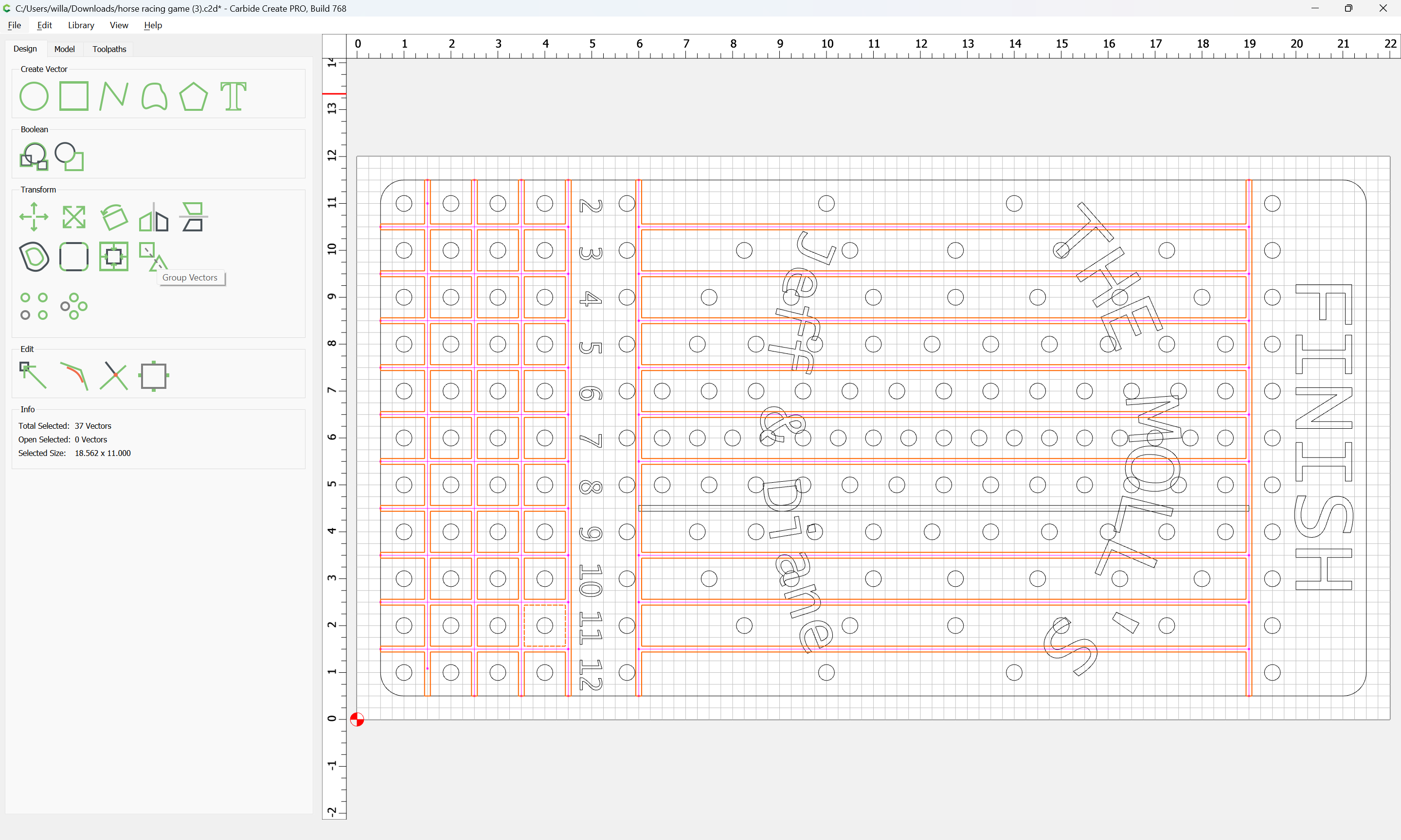
If desired, Group Vectors
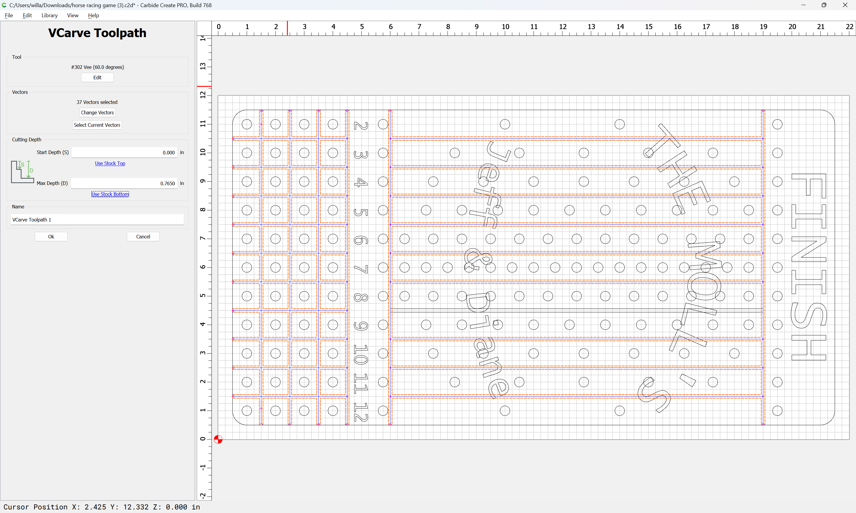
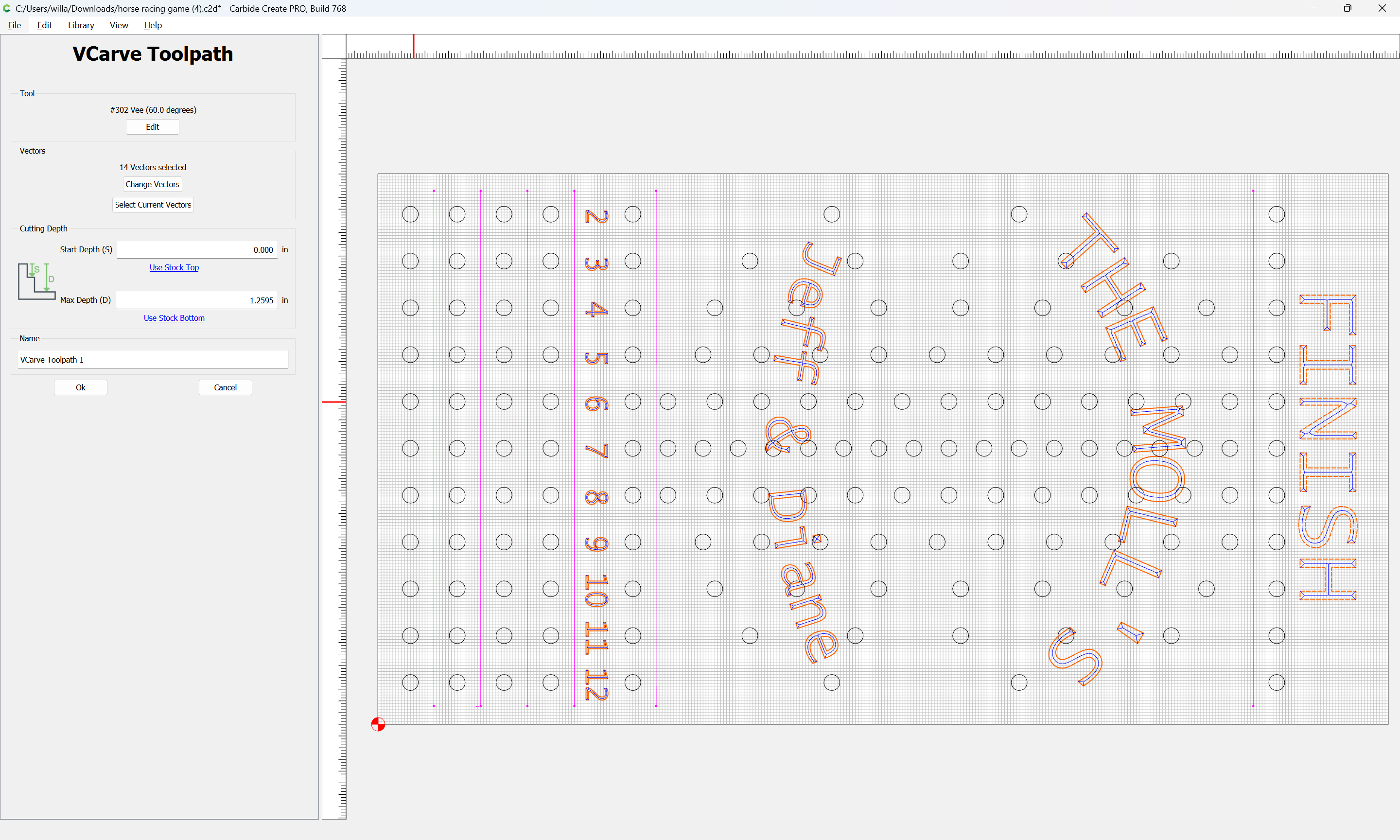
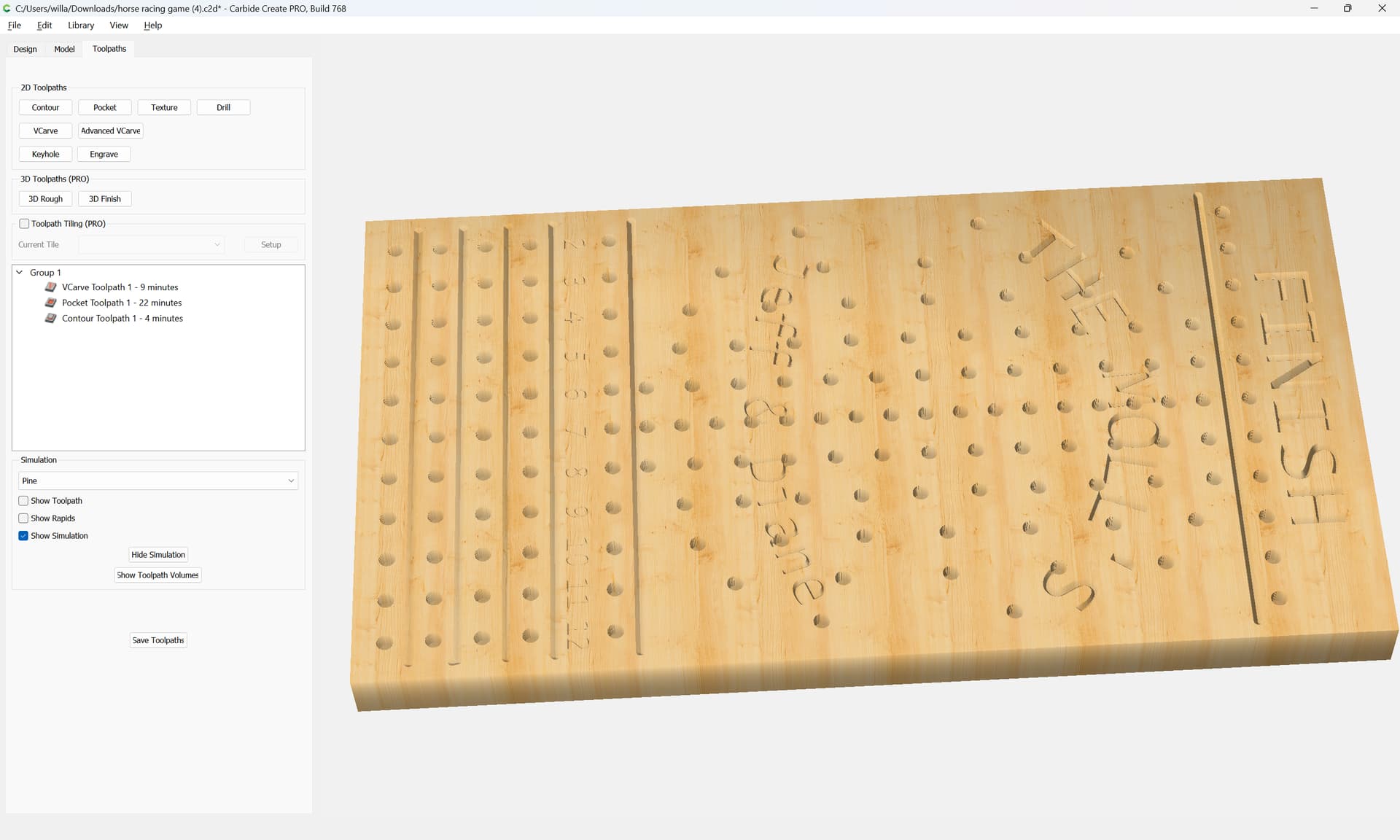
Then, a toolpath which may only be used with closed vectors such as V carving may be assigned:
1 Like
WillAdams
March 14, 2024, 1:00am
2
as requested on support…
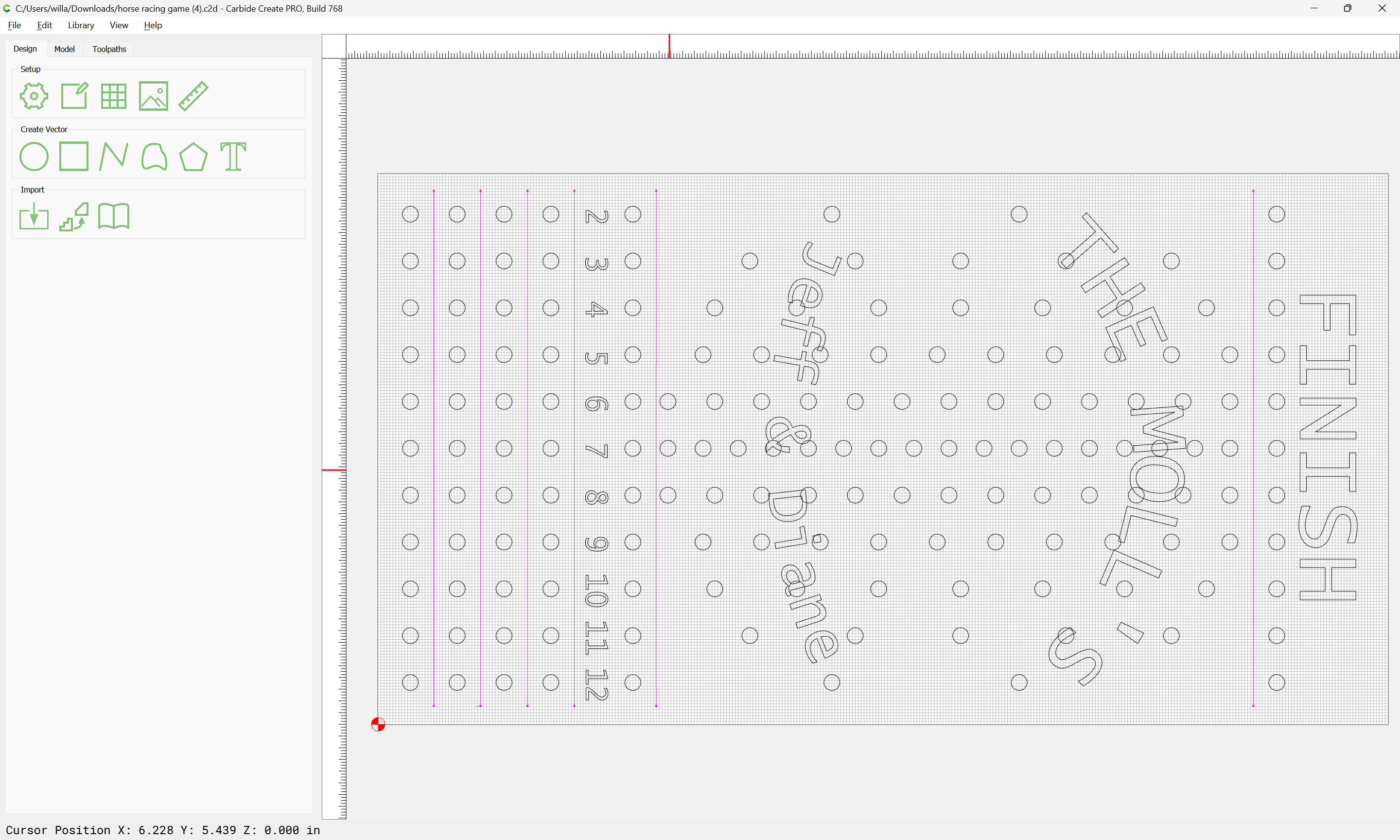
Given a file:
of which is said:
When I try to pick items for separate toolpath, the whole file goes red. I want to v-carve the lettering and numbers.
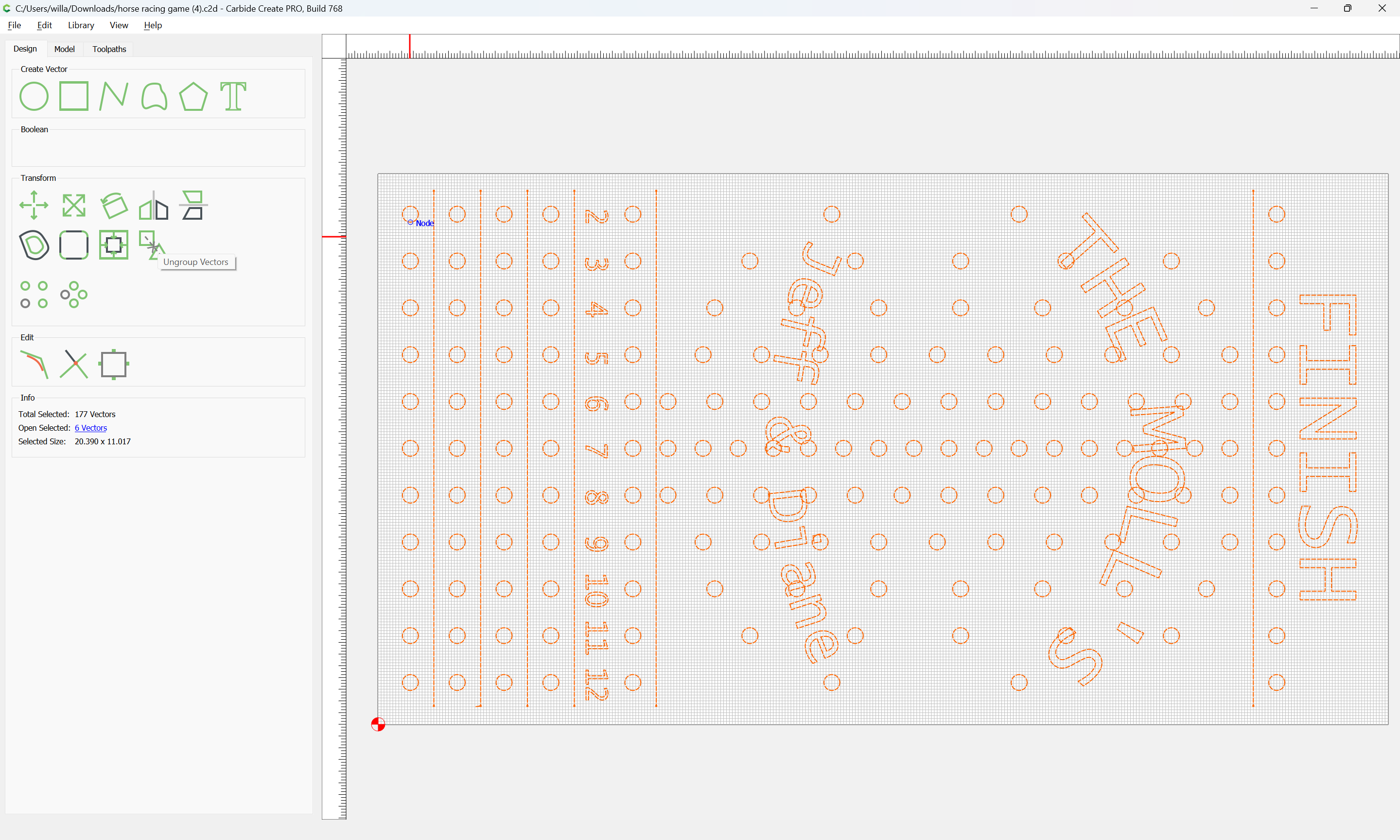
This is caused by everything being grouped:
So things may be treated separately if one ungroups them:
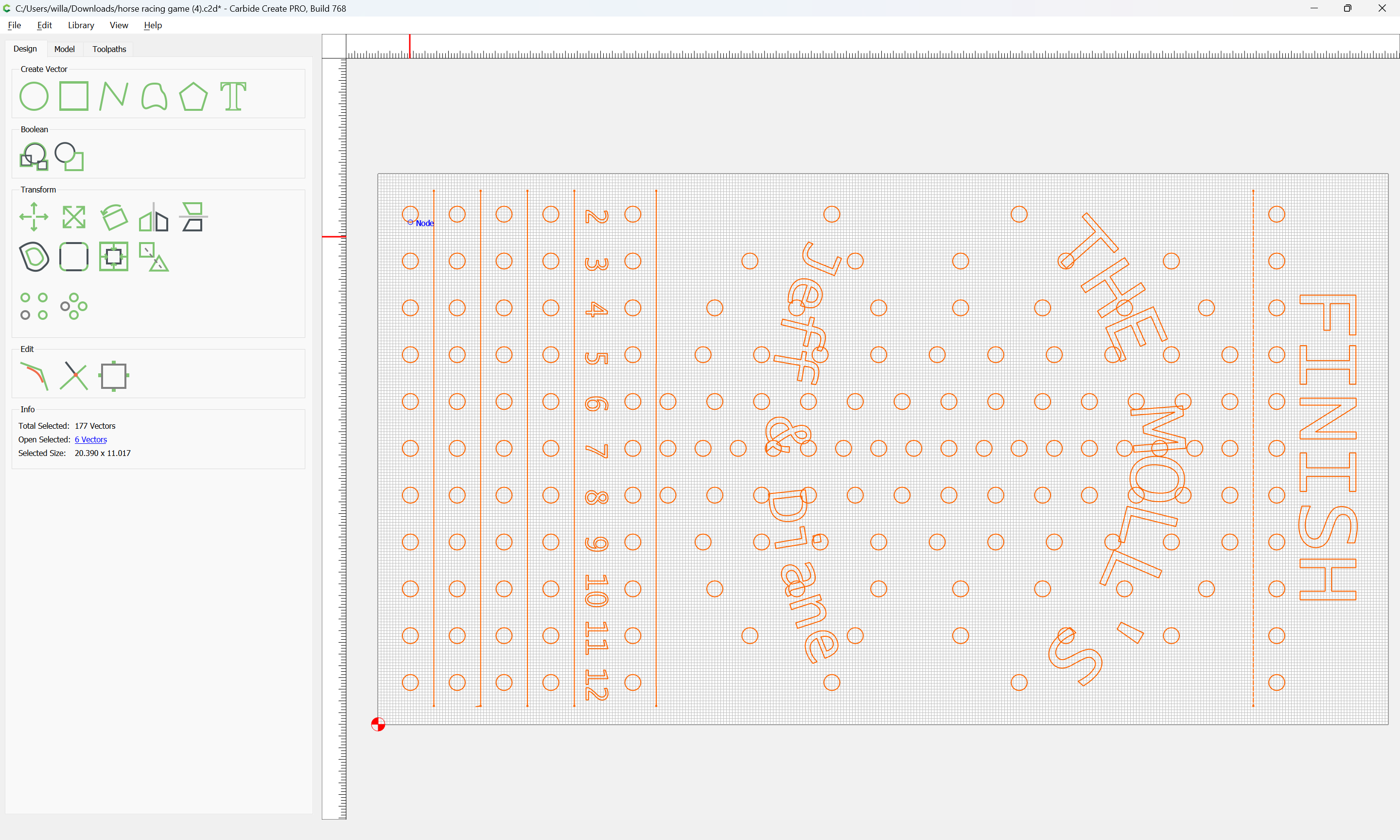
which allows one to select the lettering and numbers:
and assign a V carving toolpath:
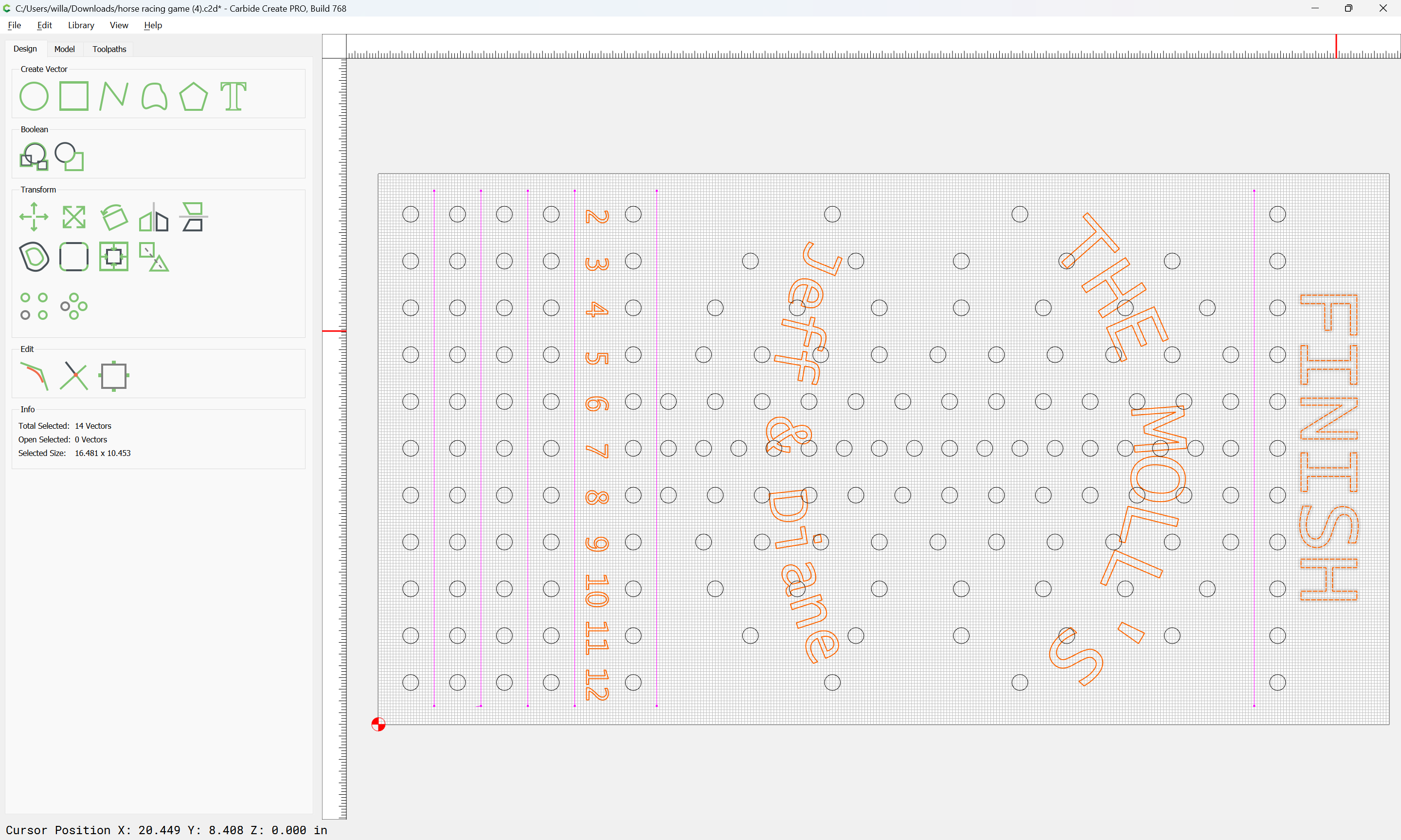
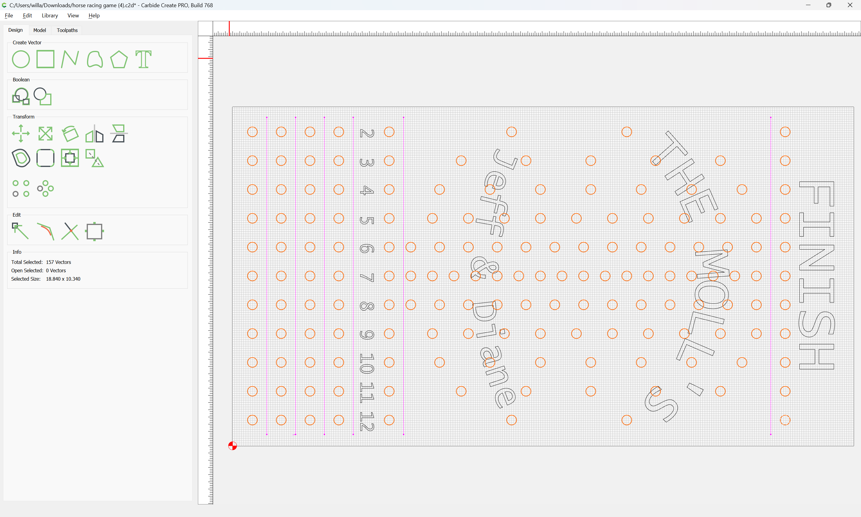
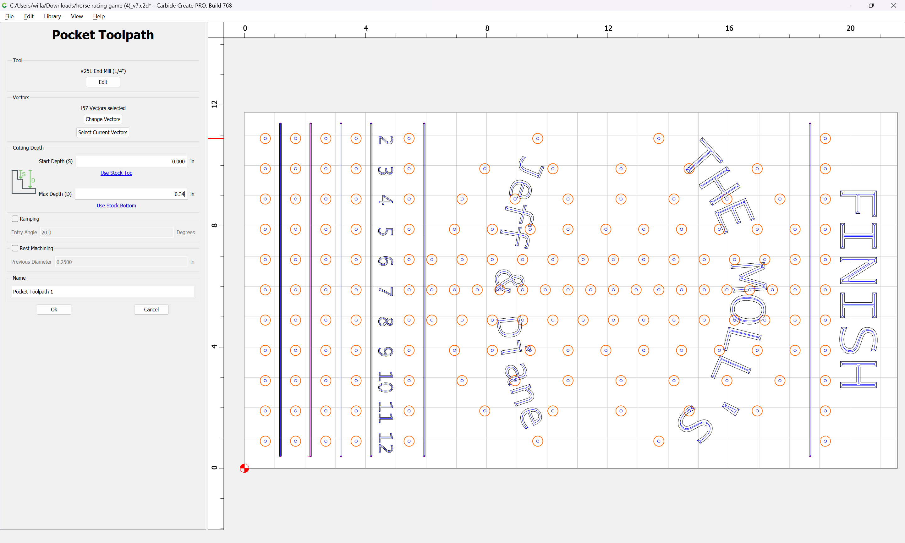
The holes along each track I want to pocket, these are for pegs to fit into.
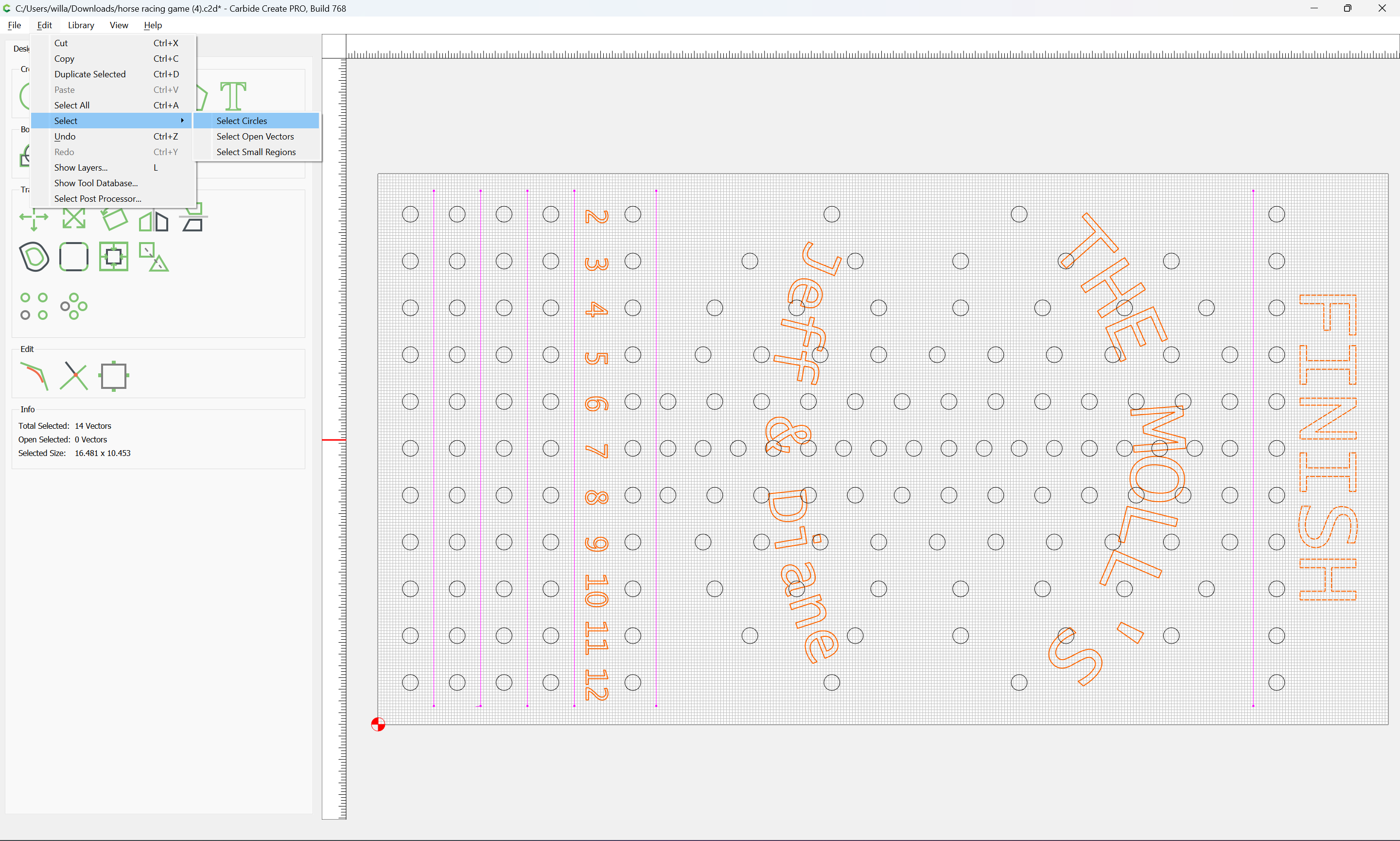
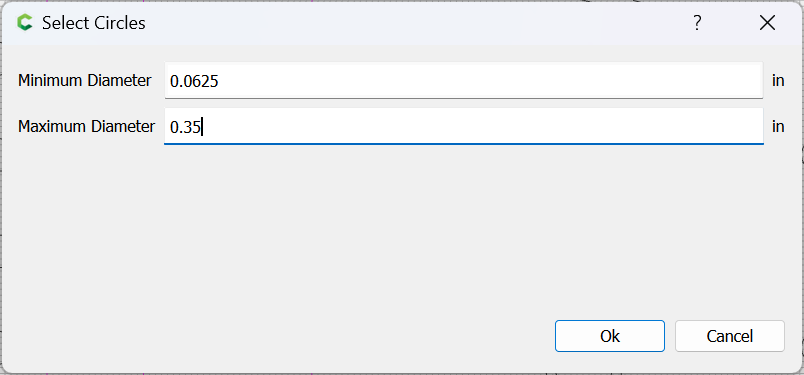
Circles may be selected by Edit | Select Circles:
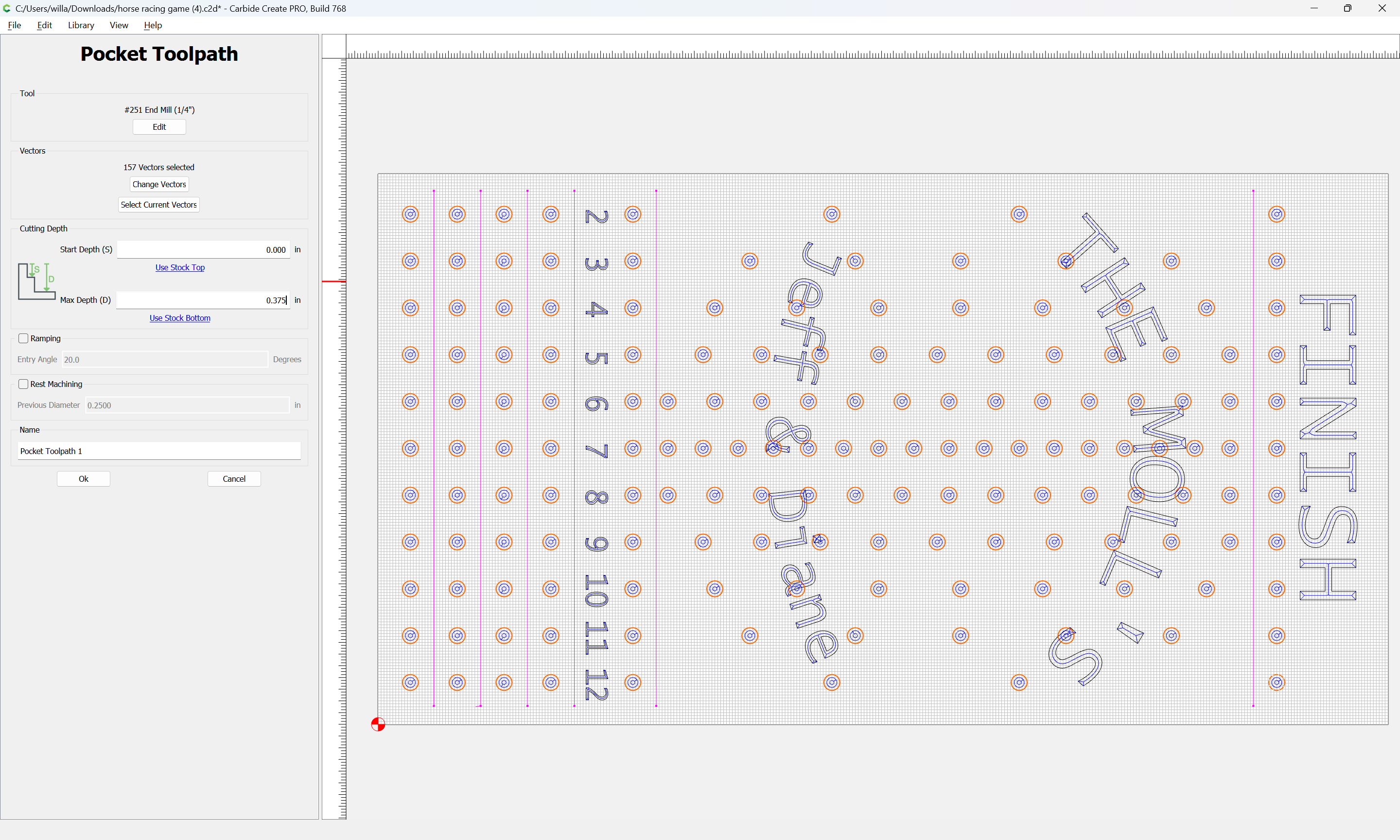
and a pocket toolpath assigned:
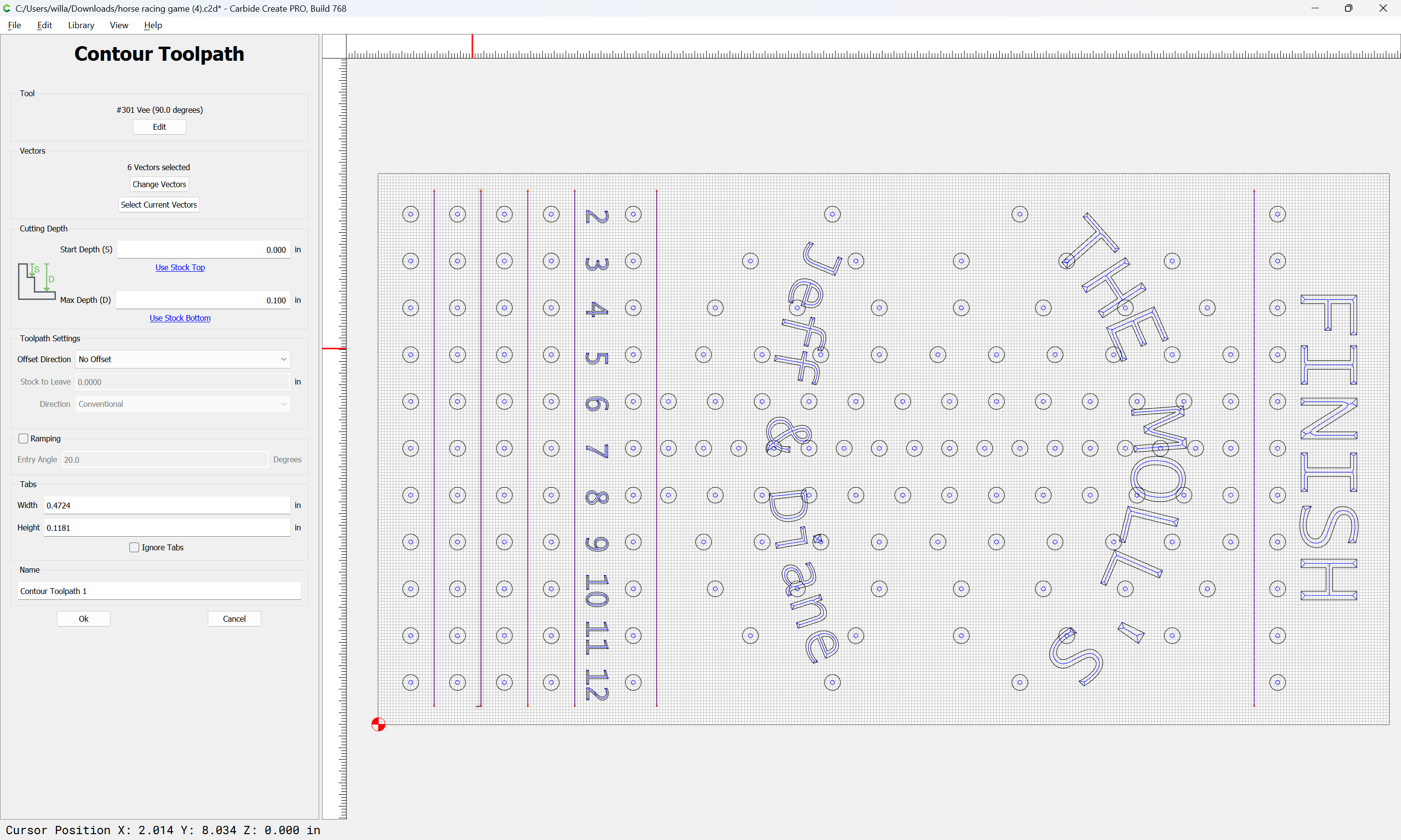
The vertical lines are not closed to create a toolpath with
Open geometry may be used for Contour toolpaths:
Or, as noted above, one may re-draw them as zero width rectangles by holding down the control (command on a Mac) key:
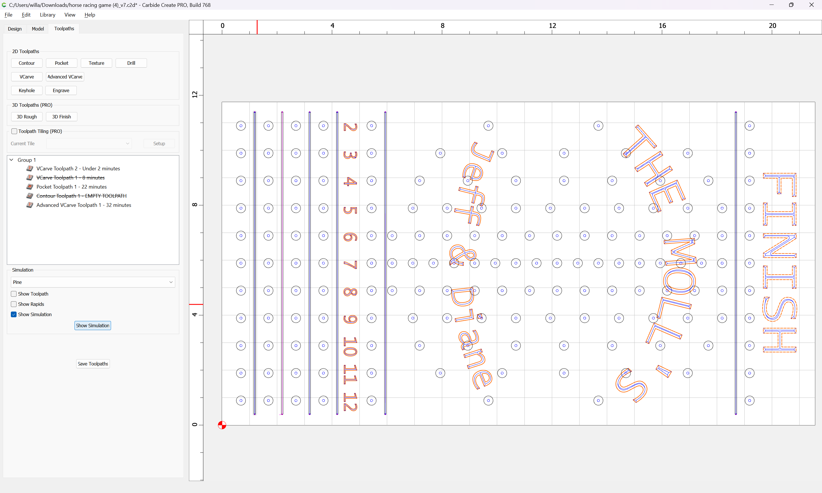
WillAdams
March 14, 2024, 2:11pm
3
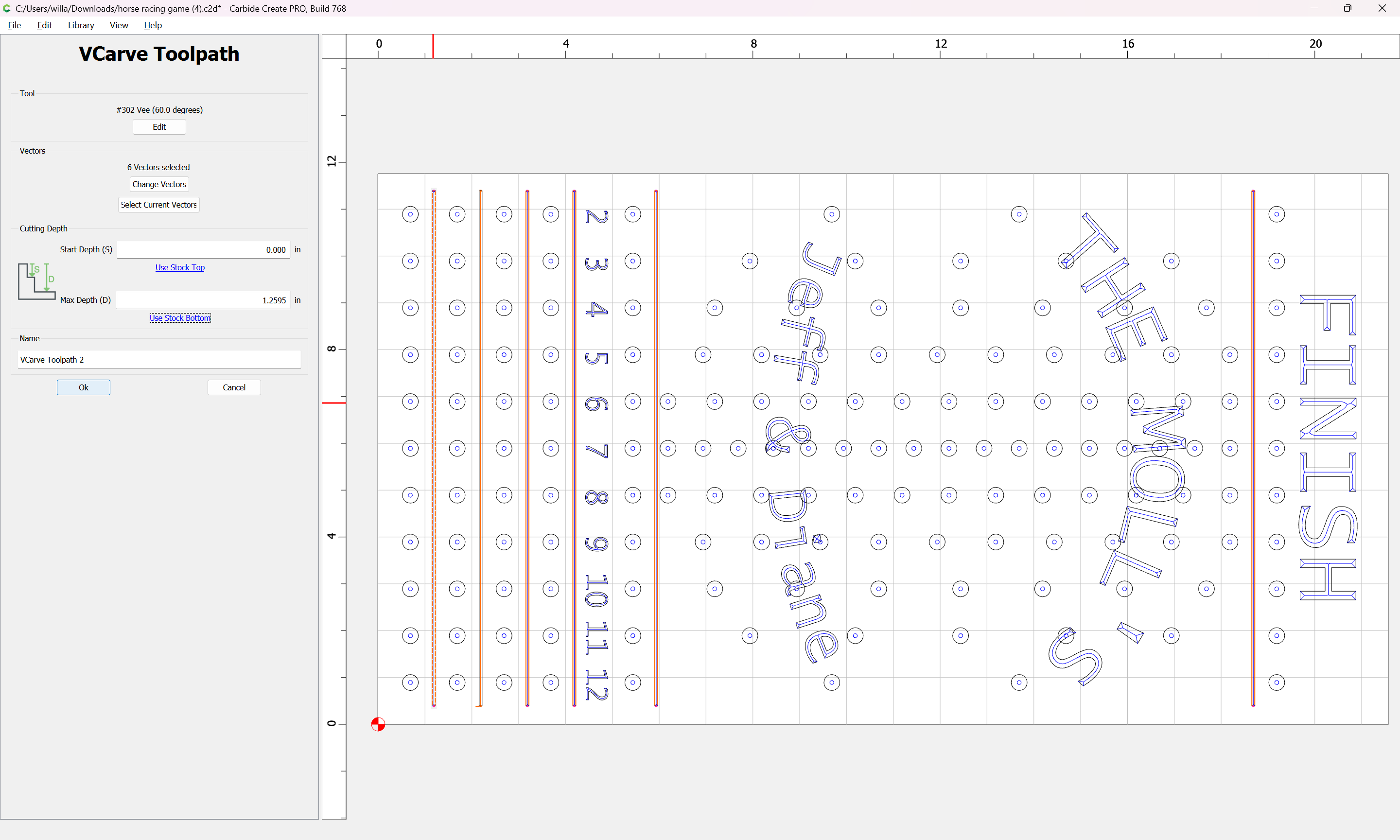
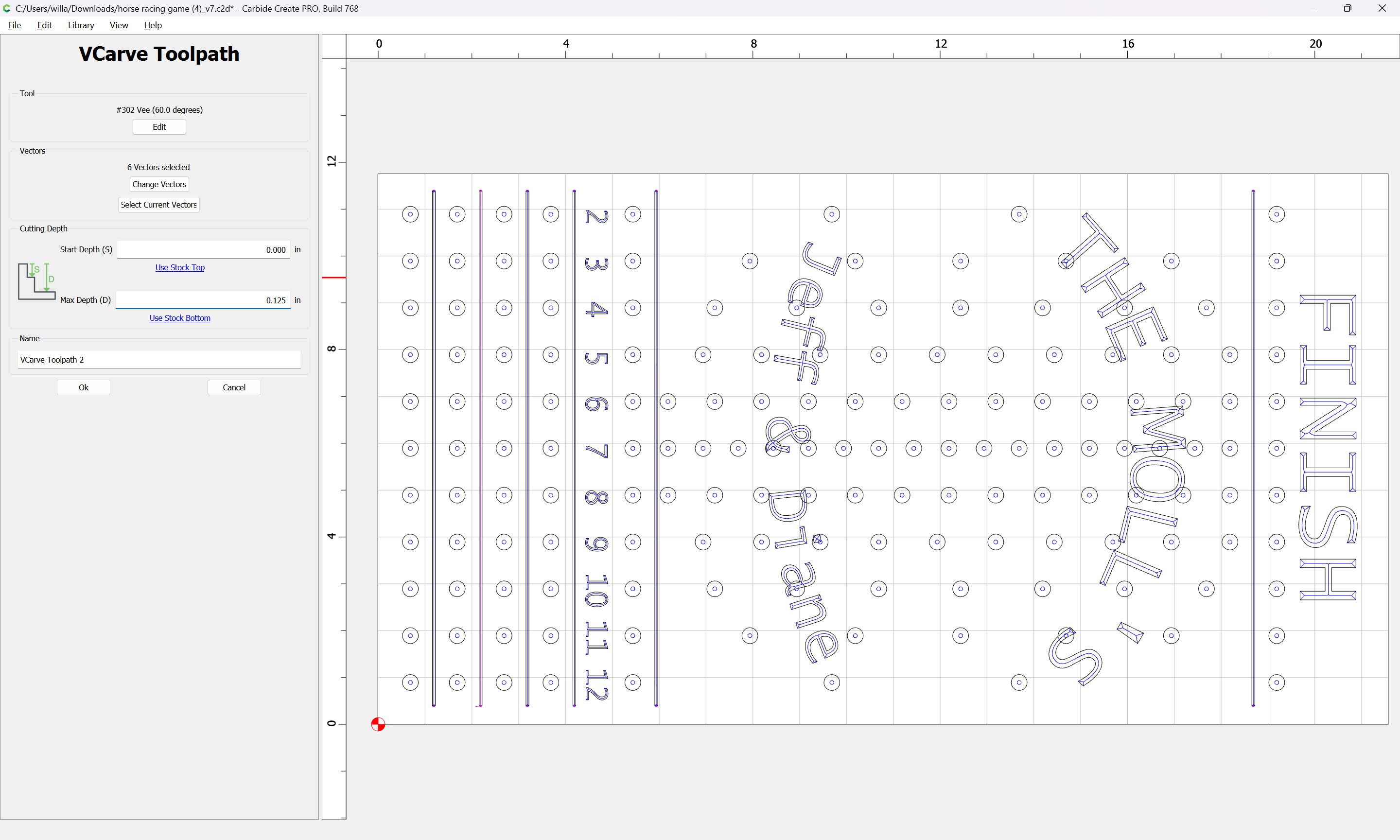
Note that for V carving toolpaths, as discussed at:
https://my.carbide3d.com/gswso/12/
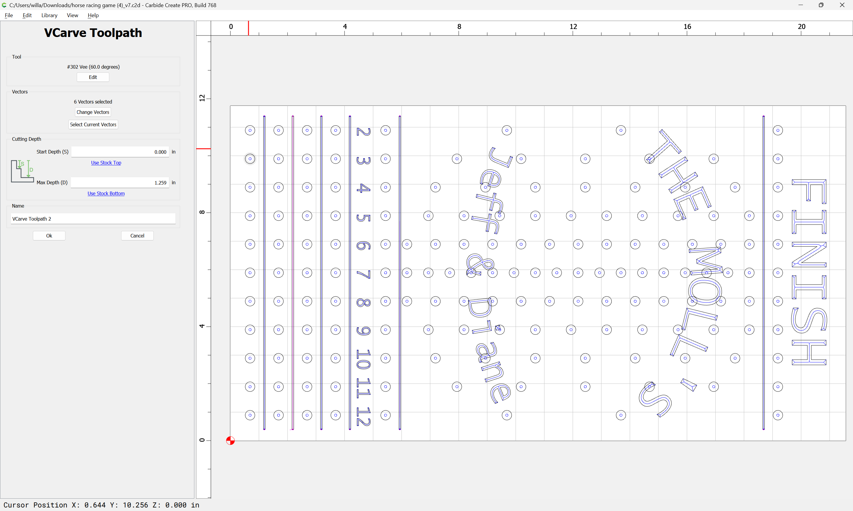
It is usually not necessary to depth limit them if they are composed of narrow geometries — although it is expedient to set the Max Depth to Stock Thickness:
Reducing that dimension will not alter how how the first toolpath cuts:
and modifying the other will result in a distorted appearance:
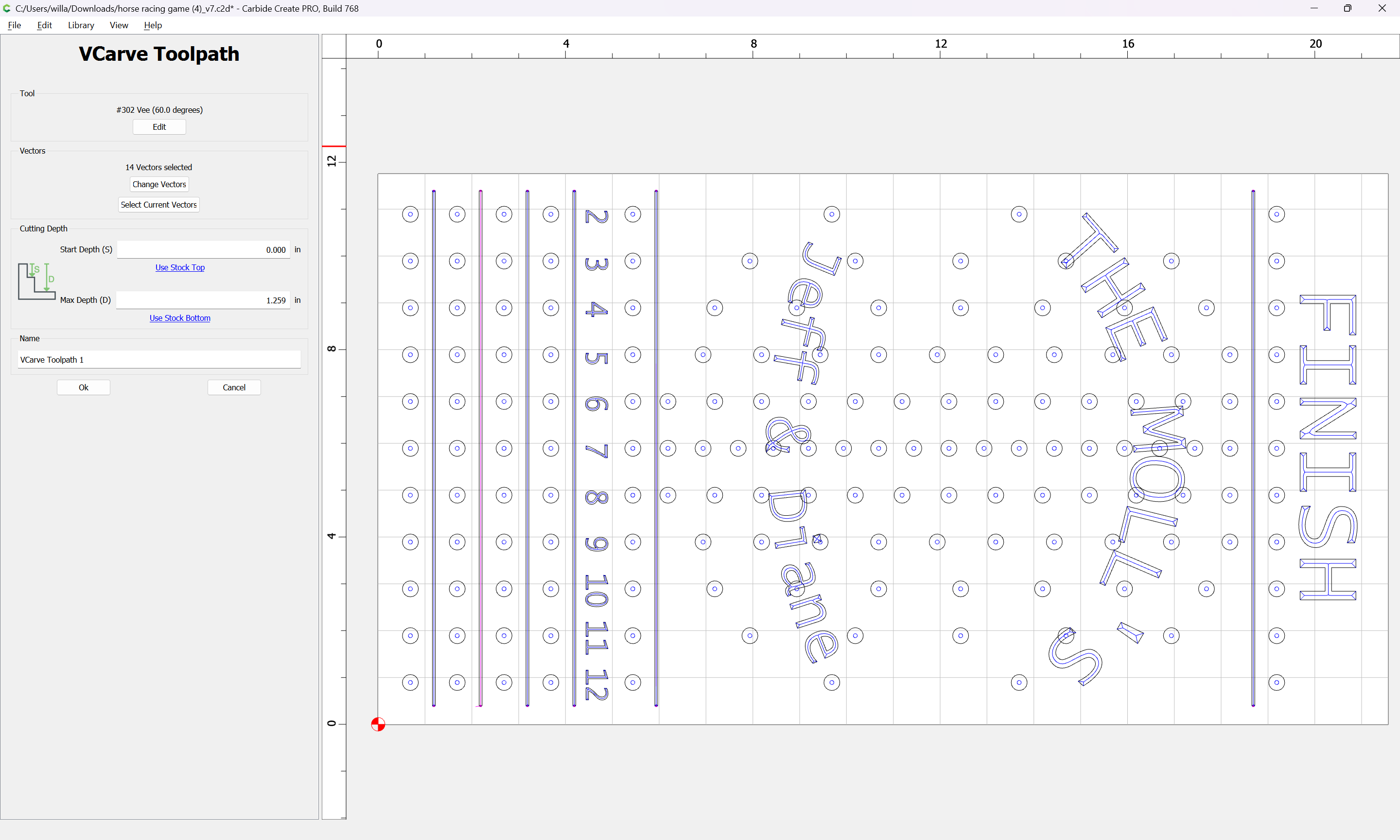
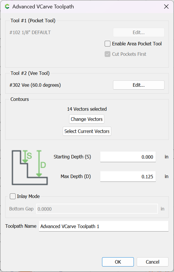
If it is actually necessary to depth limit a V carving toolpath, then an Advanced V carving toolpath should be used instead:
If the depth for the Pocket toolpaths needs to be changed, this is easily done by editing the toolpath:
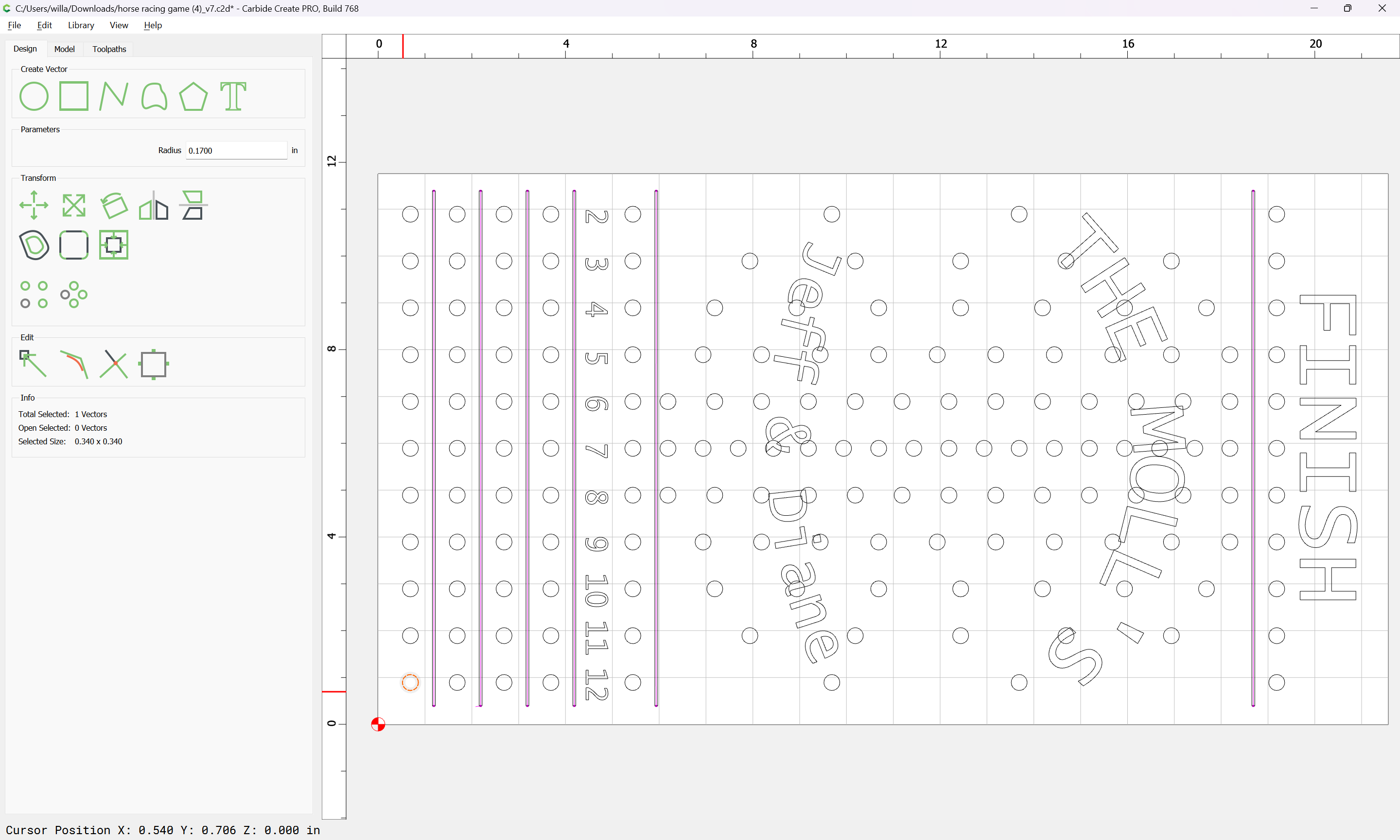
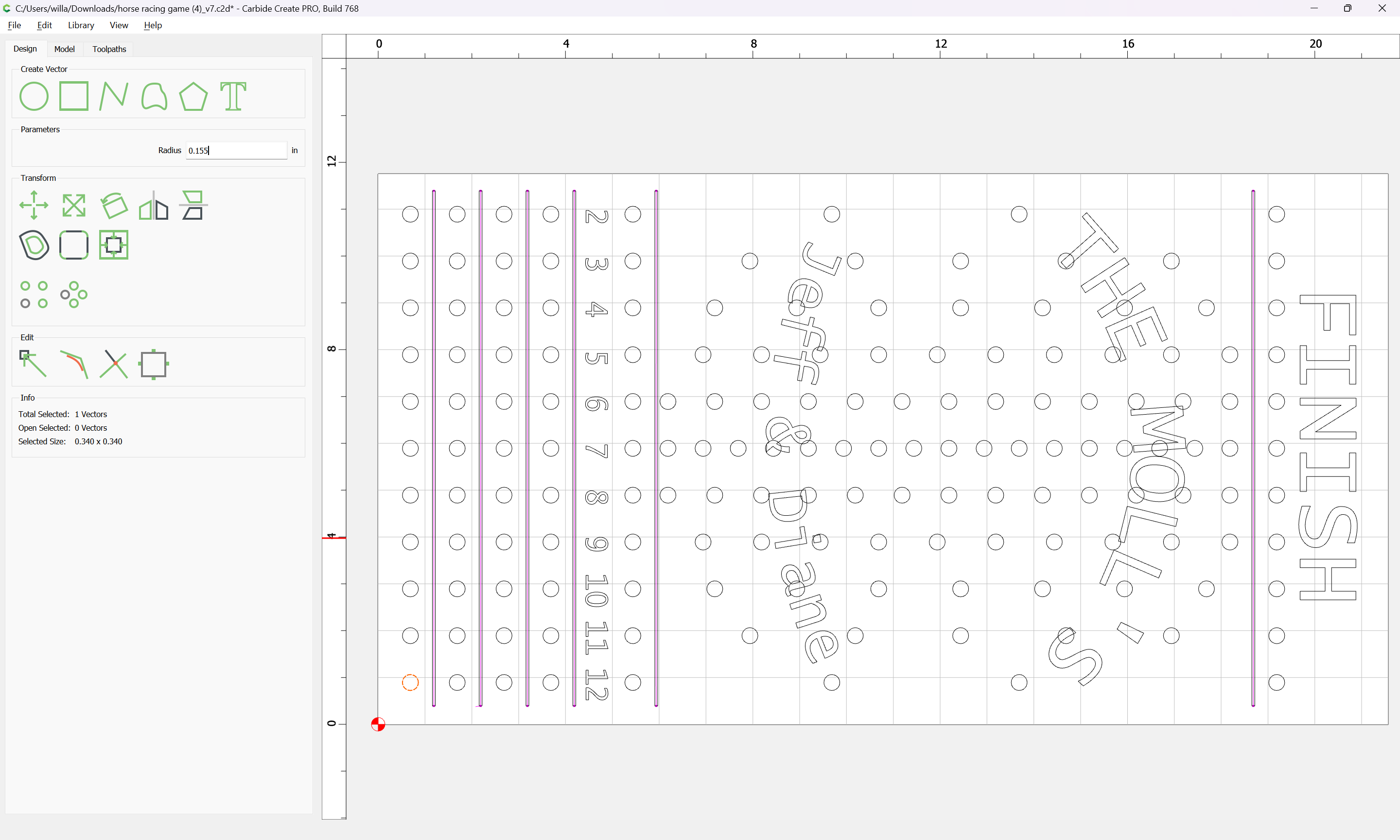
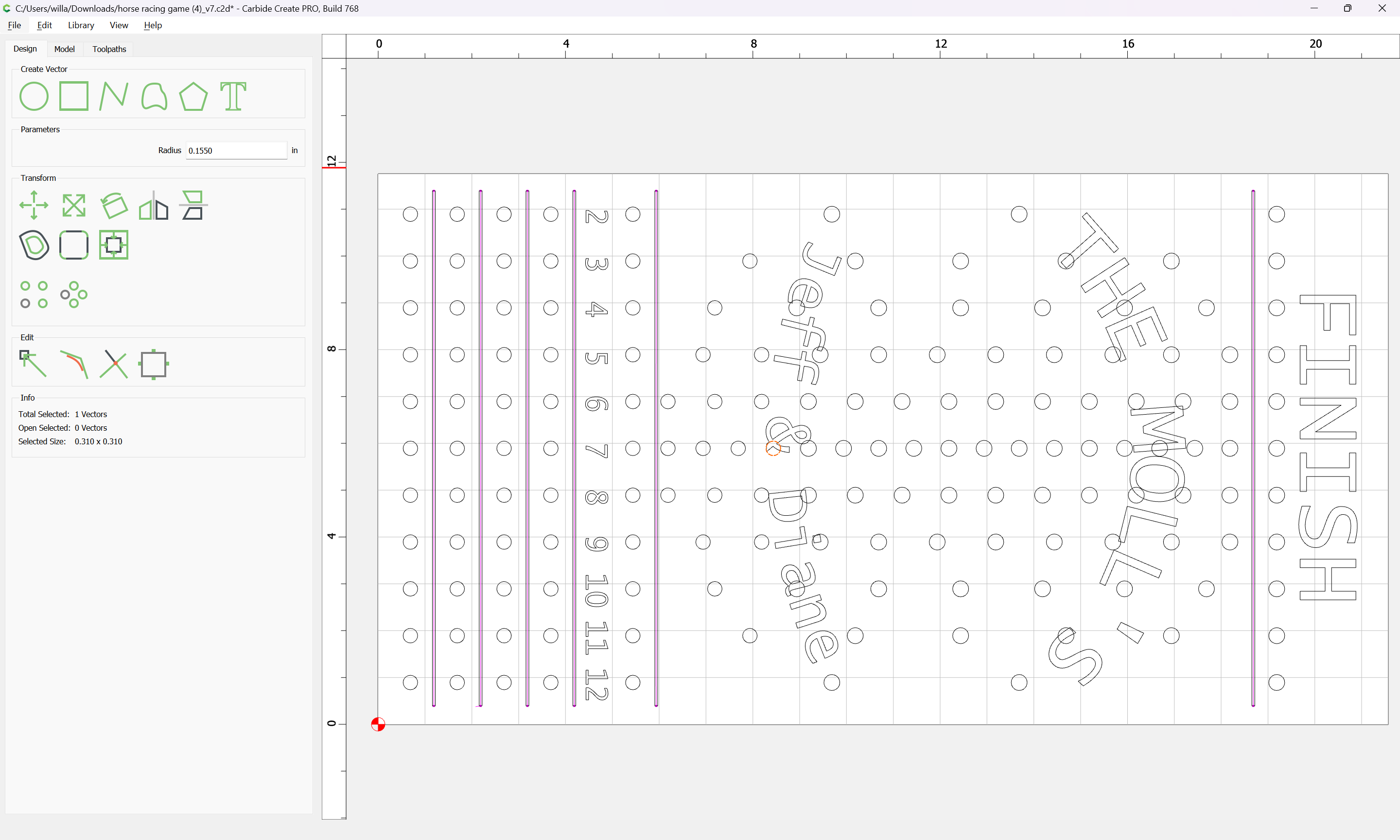
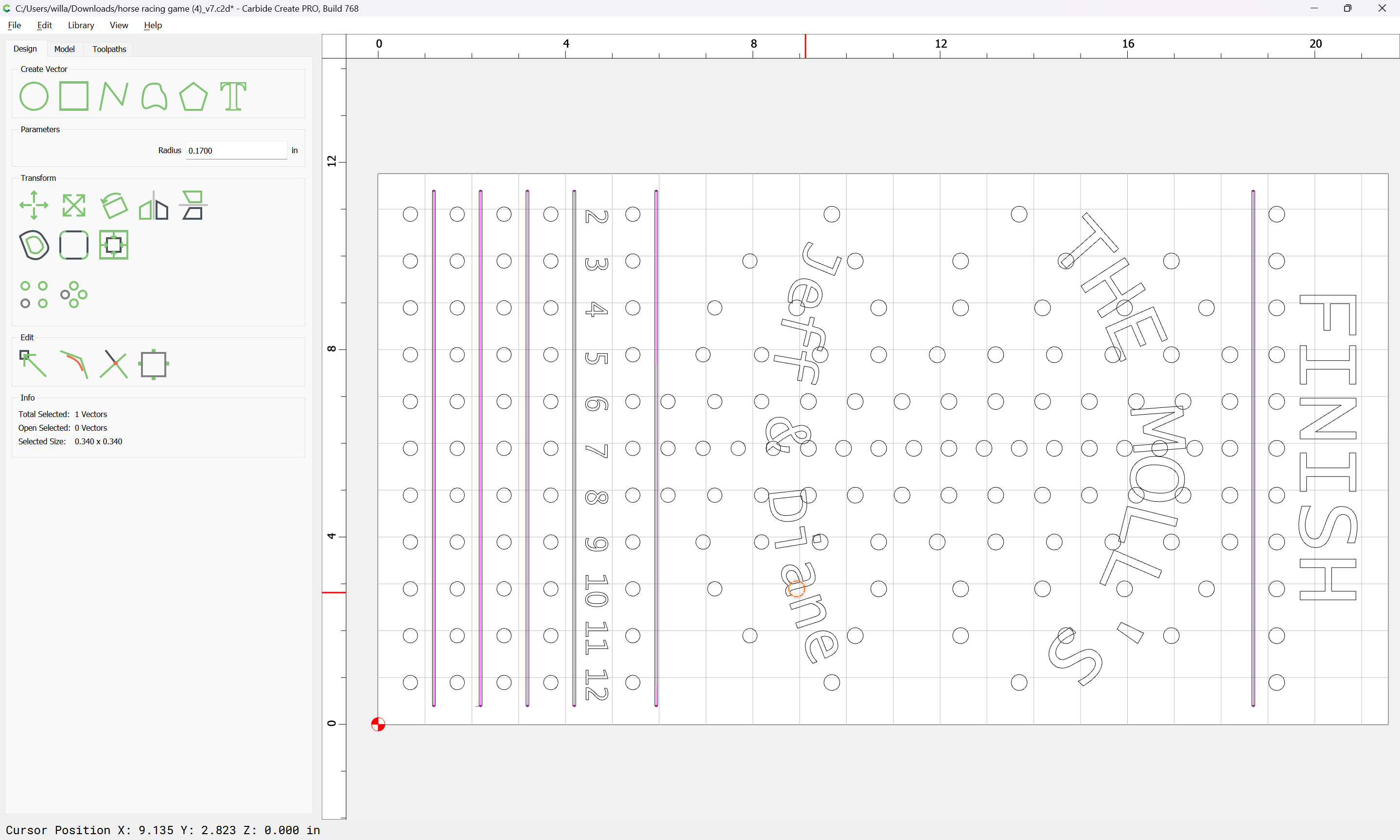
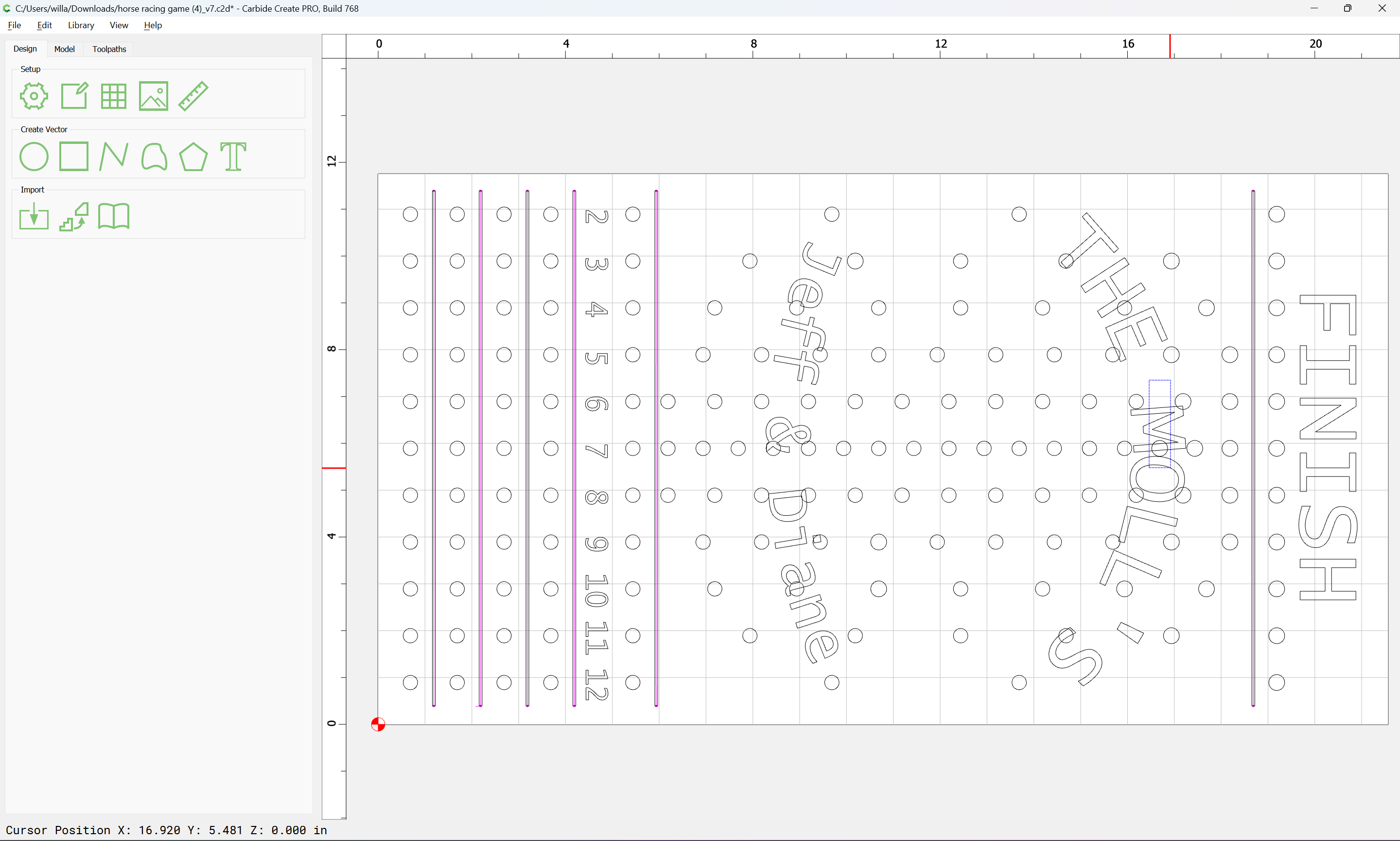
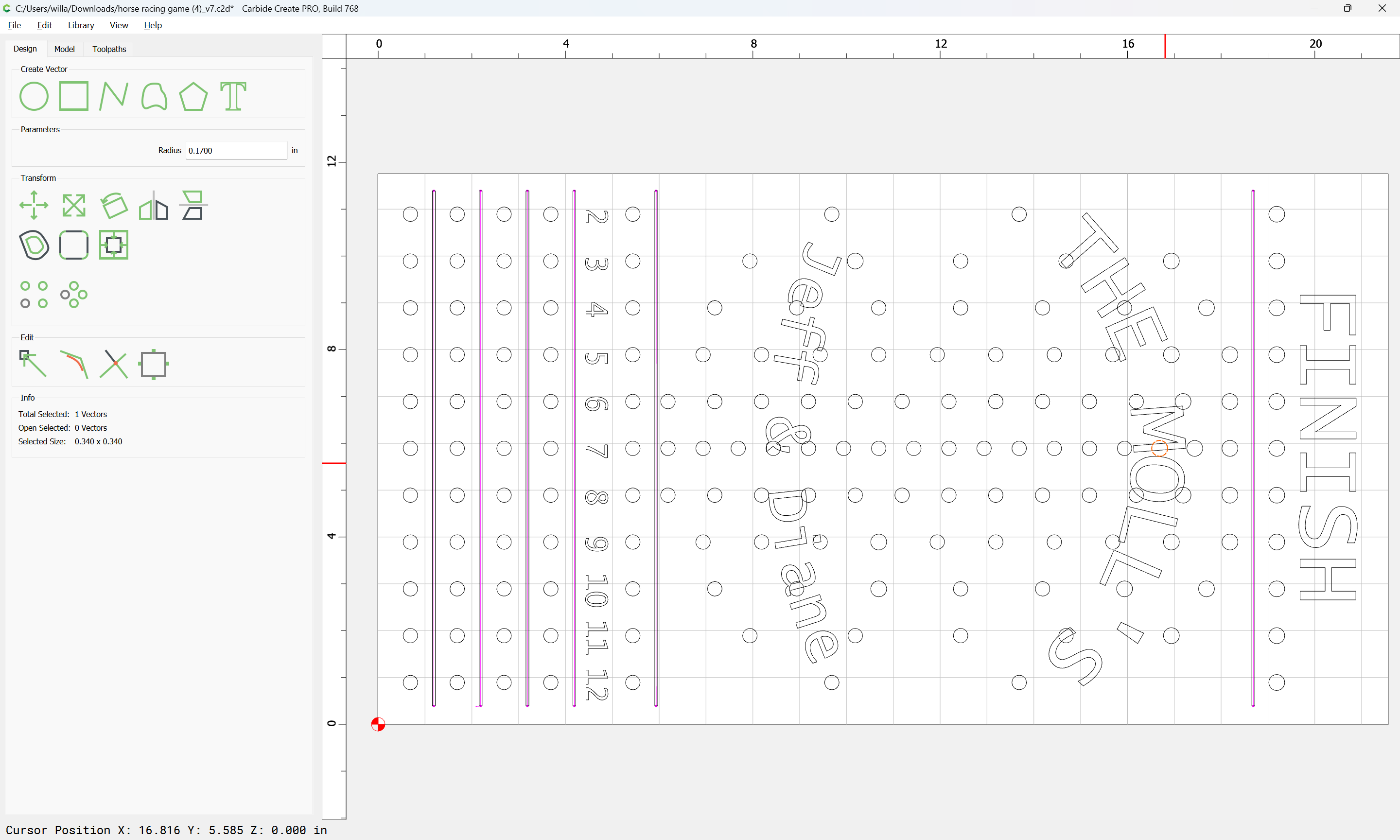
If the circles are the wrong size, then select each one in turn:
and change the dimension:
for each.
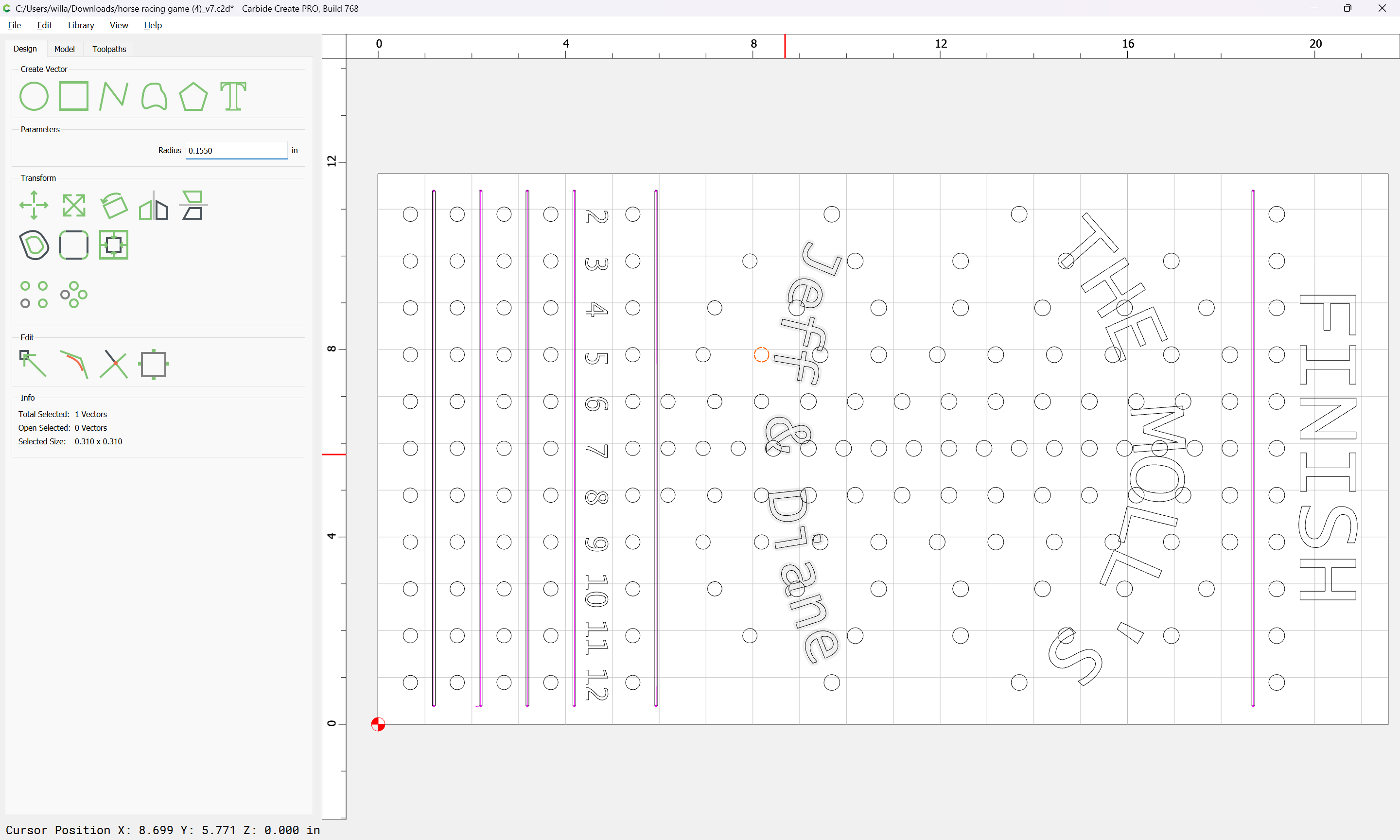
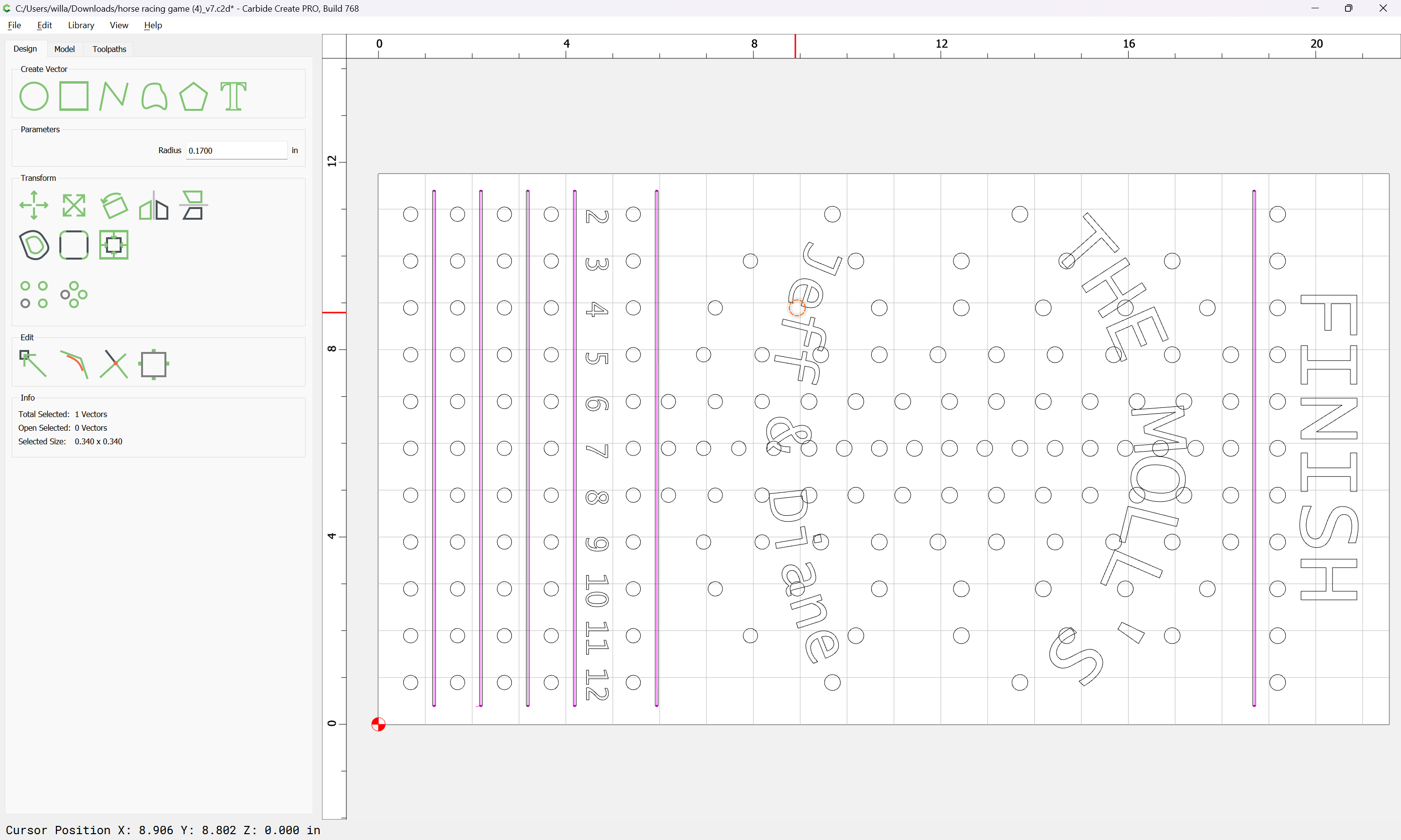
Note when selecting, the geometry which will be selected will highlight:
(text)
(circle)
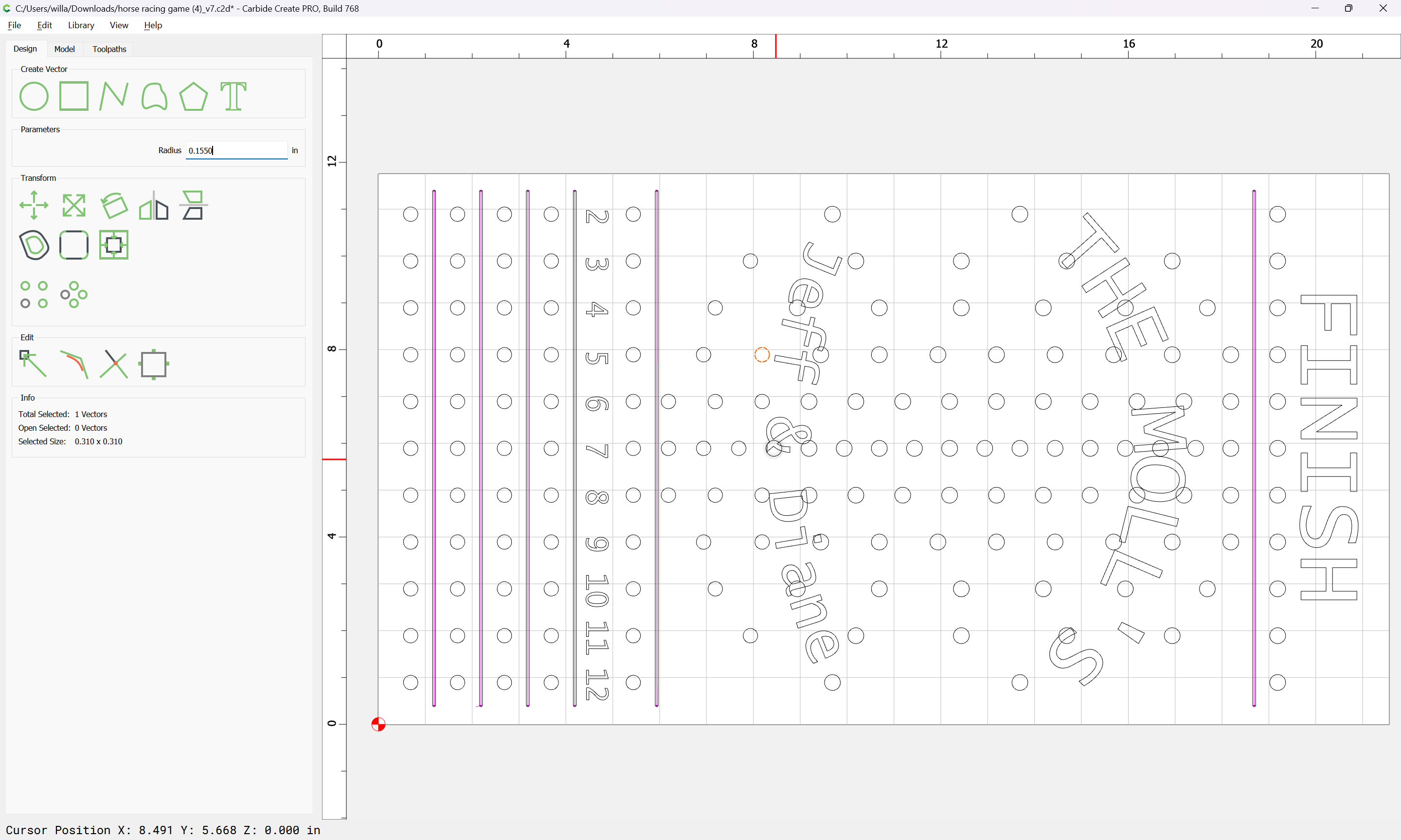
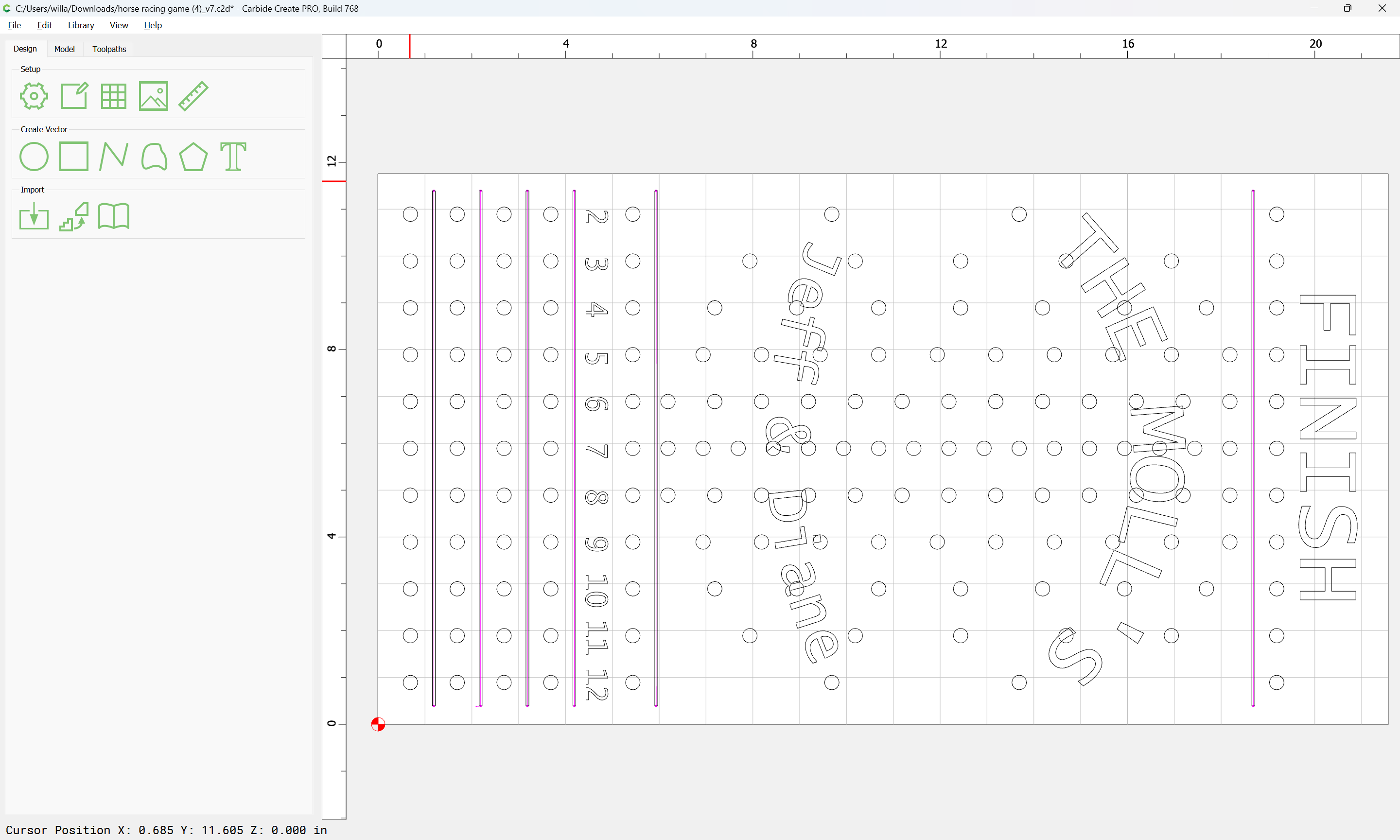
Usually it is possible to position the cursor so as to select any geometry which is underneath:
with a click:
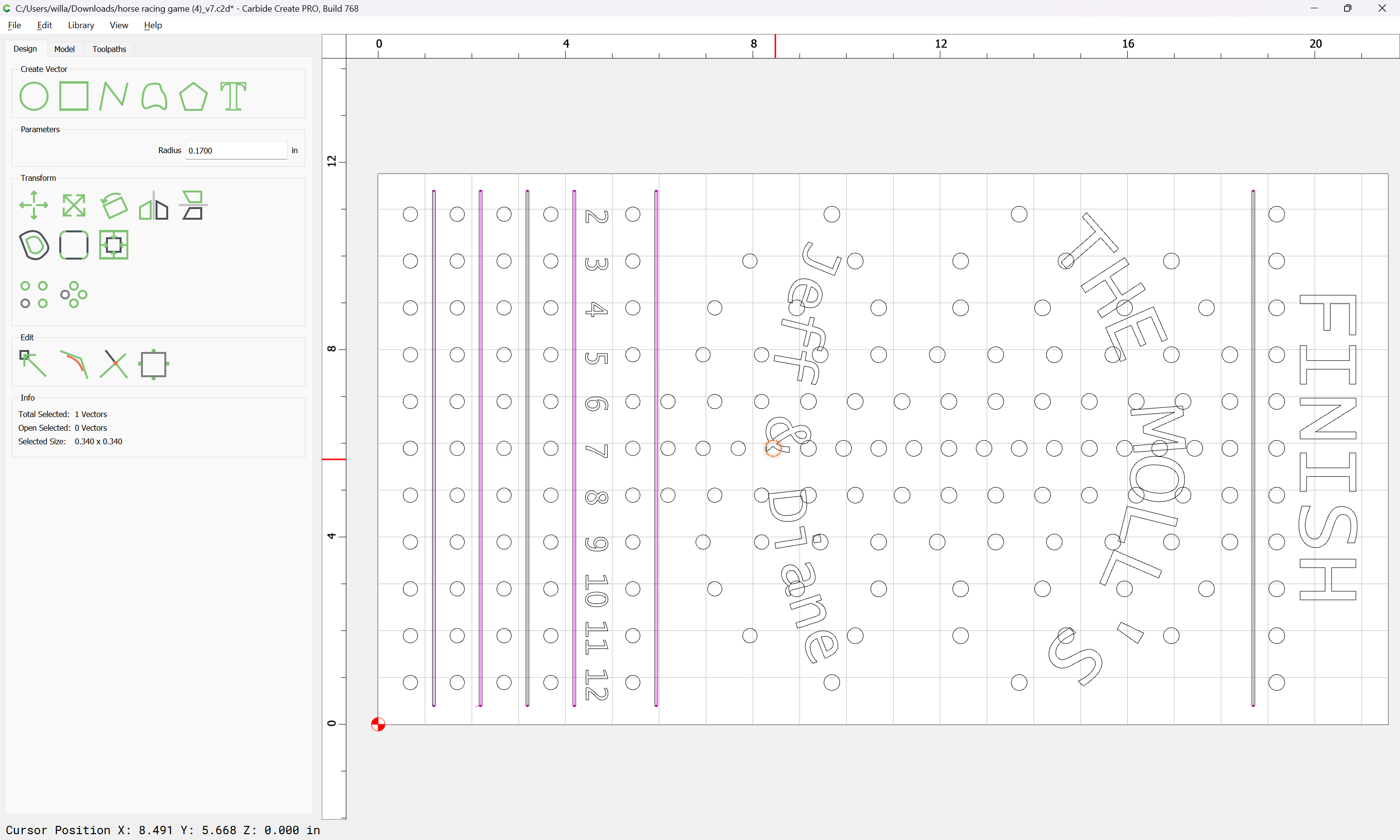
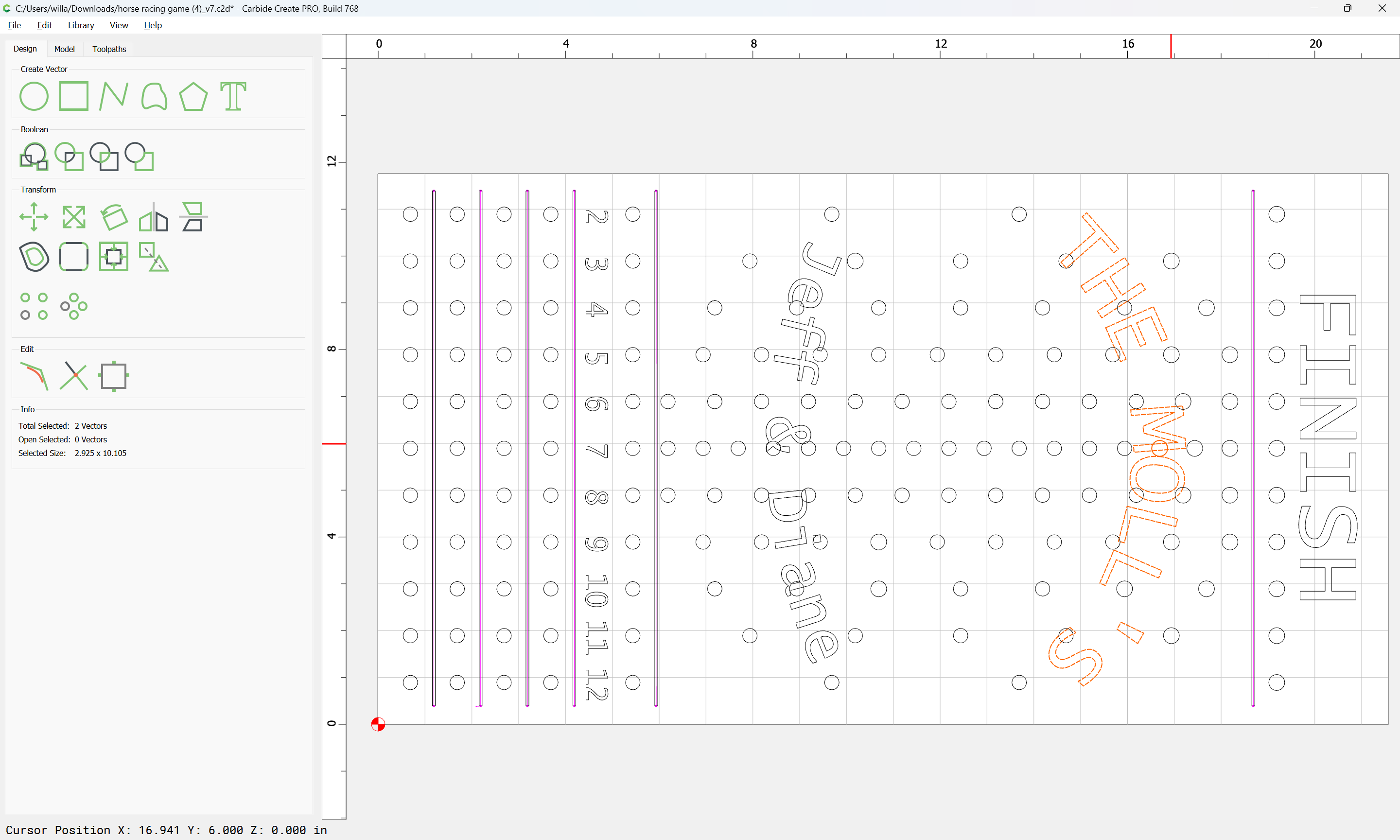
Where that is not an option, note that drag-select has two modes:
drag up is promiscuous and selects everything which is even partially within the drag rectangle
drag down is selective and only selects that geometry which is fully within the drag rectangle:
(or one can zoom in for a given element)
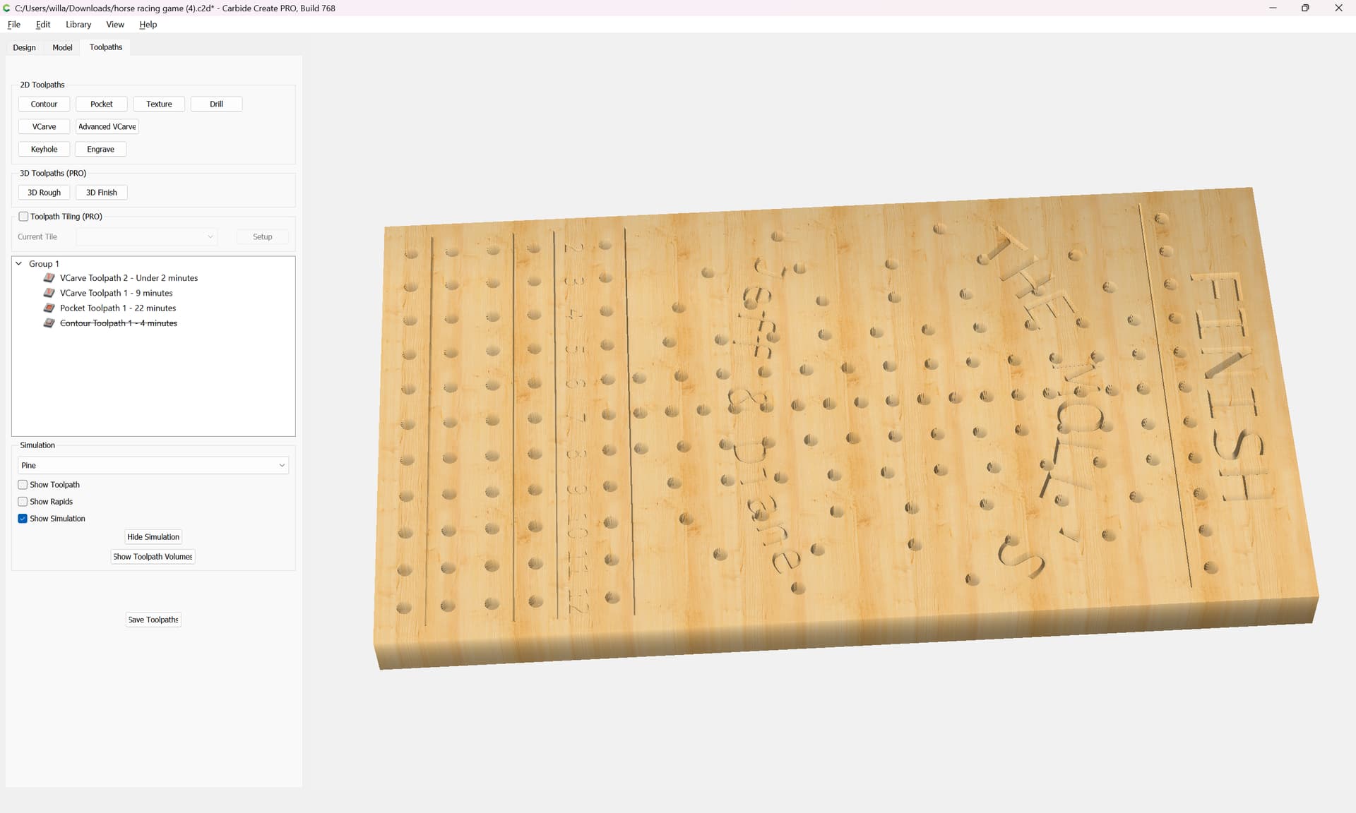
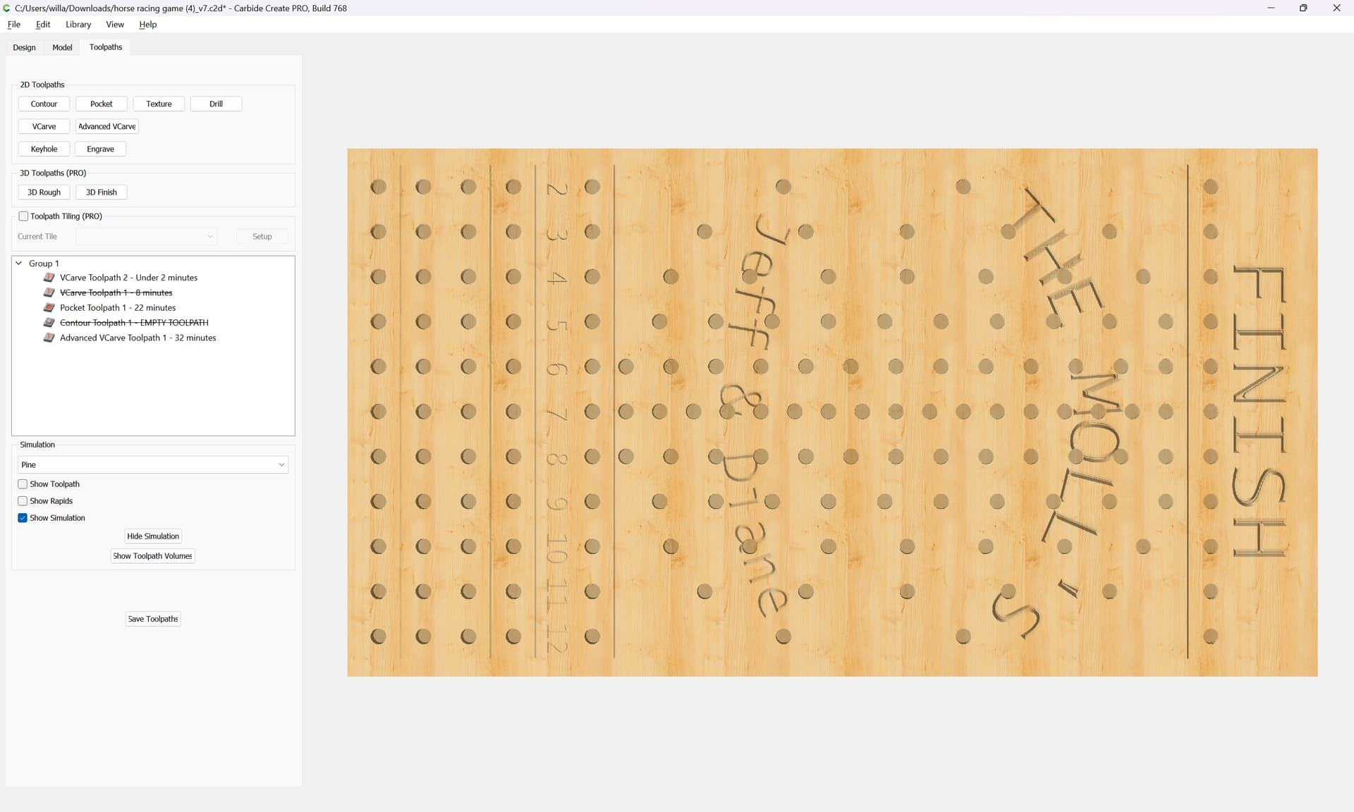
As discussed in:
https://my.carbide3d.com/gswcc/05/
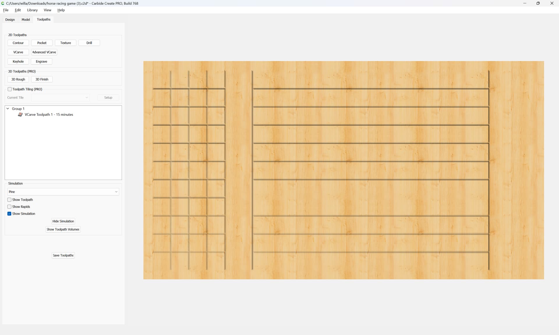
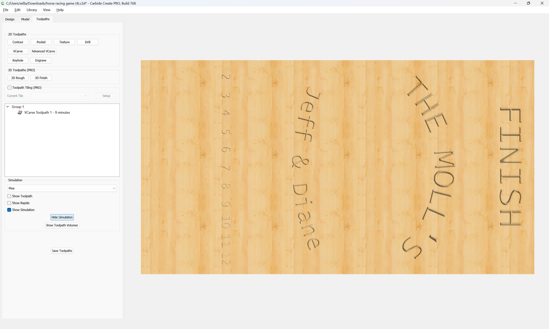
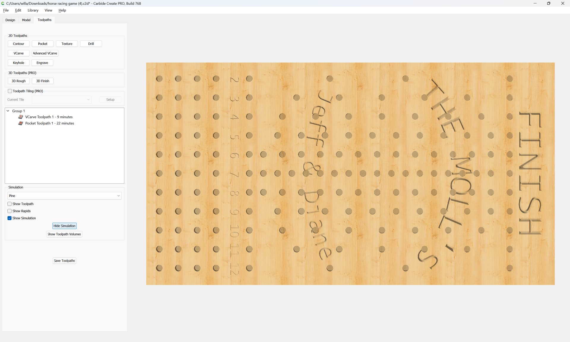
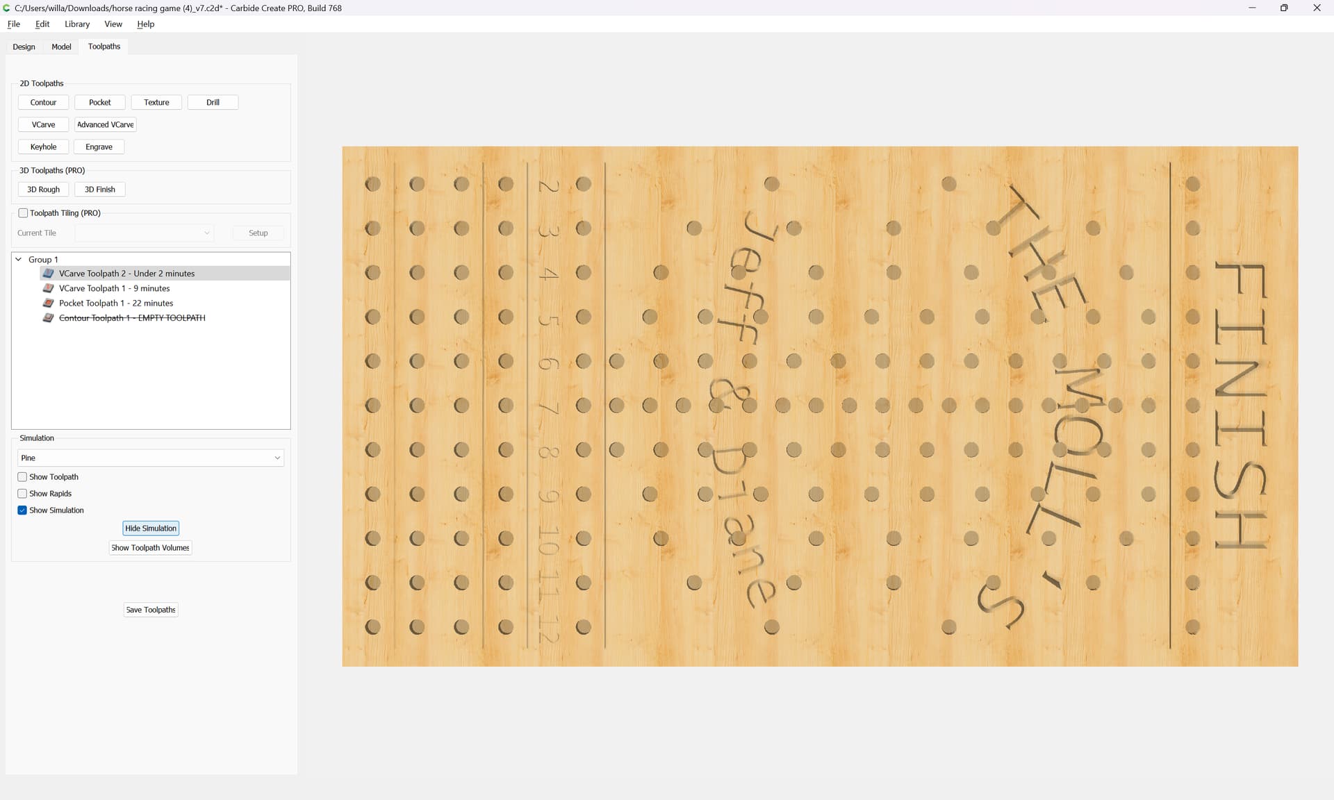
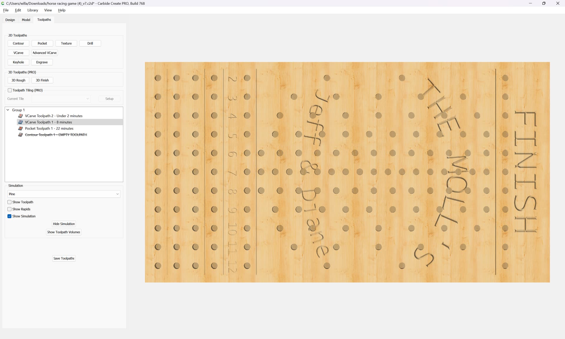
Eventually one arrives at:
system
April 13, 2024, 2:11pm
4
This topic was automatically closed 30 days after the last reply. New replies are no longer allowed.