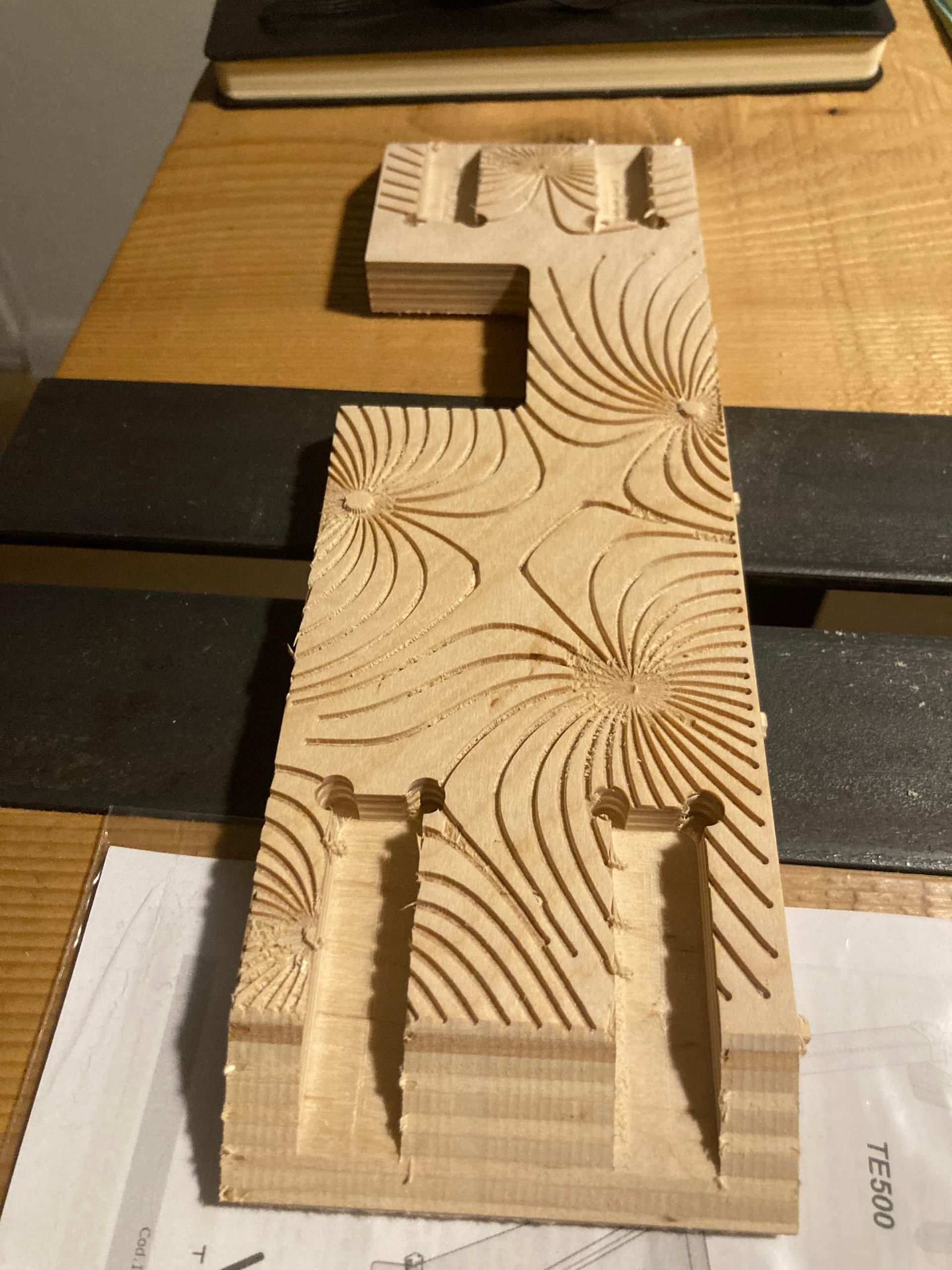
I am trying to engrave a magnetic filed line pattern in a piece of ply. I am creating the lines in Rhino+Grasshopper, exporting in dxf after rebuilding the curve with a reasonable point count, dropping into a fusion sketch and trying to use the lines to run an engraving toolpath with a 35° v bit. Now I got a reasonable result as a first try but I am trying to improve the following:
if I select the whole sketch as machining geometry I get empty toolpath and a warning suggesting to adjust the tolerance, but doing so doesn’t change anything and to obtain some result I have to select one by one the curves…
the tool paths are not smooth and you can actually see the gantry moving in a very “unsmooth” way…and so is the result if you look closely. It looks like the tool path follows the control points of the curves rather than the curves themselves.
picture of my first try attached.
here is the link to my fusion file but I am on free version so can’t allow download. And can’t also upload here the f3z…is there a better way to share my fusion file?
I’m not super familiar with the engrave toolpath, but my understanding and how I used it once was like a v-carve to carve out an area with a v-bit. I didn’t think it would trace an open contour which is what I believe you are trying to do (just run the damn bit down the damn line, right?).
The closed contours that you have in the engrave toolpath are formed from your smooth curve and some construction lines. I’m not sure if you added the construction lines or if they got generated for you somehow. Either way, it looks like those construction lines are your problem. If you zoom in the view on the selected geometry of the engrave toolpath, you can see it is using the area containing the curve and the construction lines.
You can either remove the construction lines or create a new sketch and project just the smooth curves. From the new sketch / cleaned up sketch, I would use a Contour toolpath and select all the curves as Open Chains. You will need to set the bottom height and remove the lead-in and lead-out settings (from the Linking tab).
Try this. I see you were on the right path with Trace, but it’s a little tricky. On the heght tab, you need to set depth at zero. To cut the material, you have to go to the next tab and set “Axial Offset” to a negative value, and I always use smoothing with the belief it will make my gcode files smaller. And finally, on the last tab, you need to uncheck “Keep Tool Down”. bike hanger test Solution.zip (2.2 MB)
Hi everyone, many thanks for your replies. @crpalmer yes the construction lines were generated as the lines containing the control points of the spline… @Steve.Mc yes the trace operation is what I was hoping to use but I was missing the axial offset. I’ll give it a try next week but I think that’s the solution I was after.