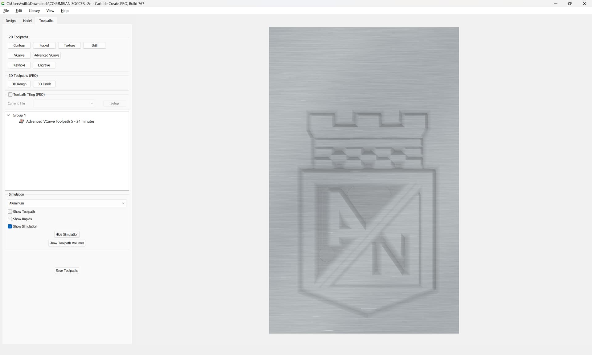
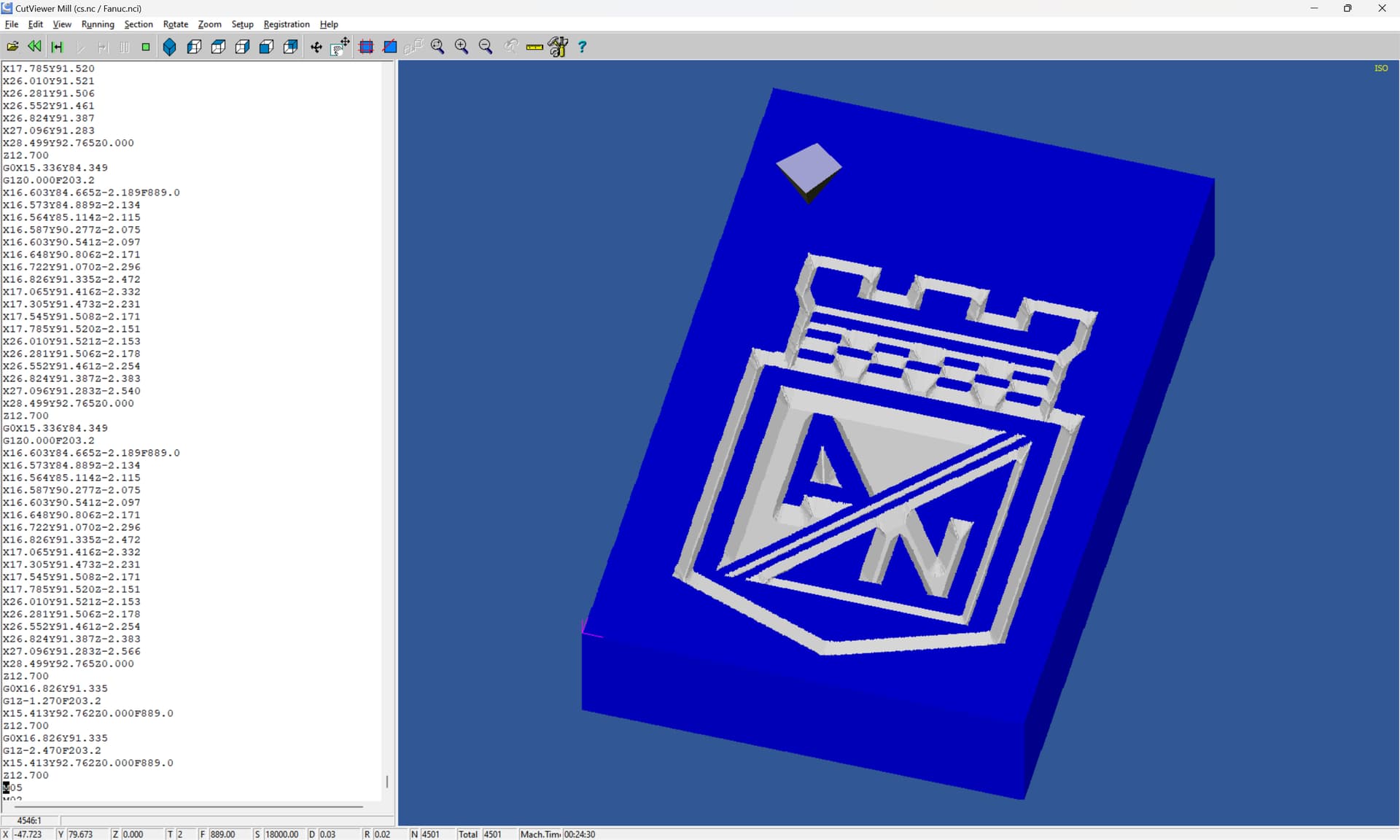
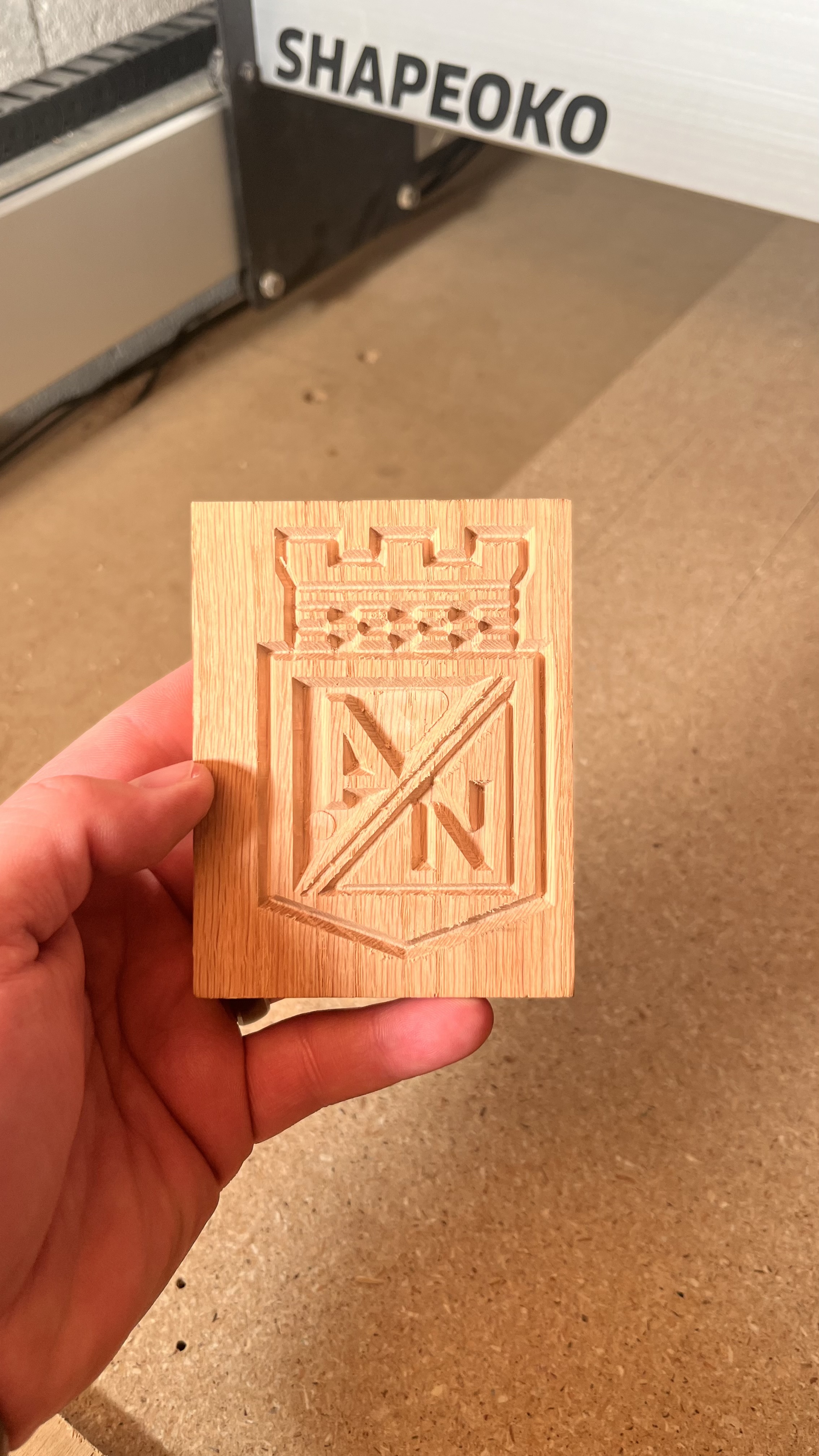
I’m very new to this and am not sure where to start with this. When I make a design in carbide create and then run the program, it looks different. I ran it a few times and the cuts look the same to each other.
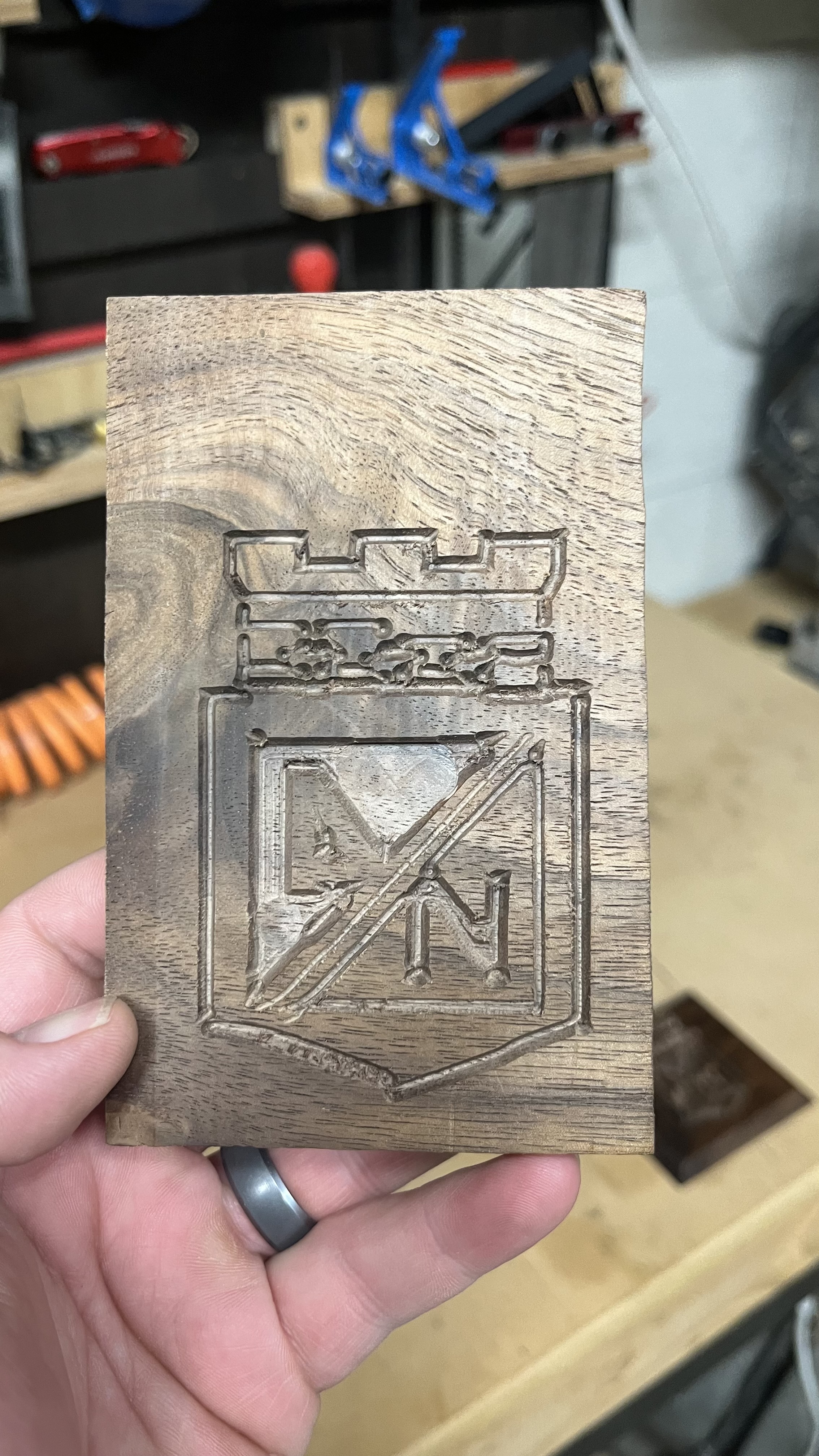
I’ve attached photo for reference.
What am I doing wrong? Is it a problem with my machine or the program?
so if the tool geometry is accurate, then the problem is something mechanical (or electrical) on your machine or some sort of interference (say a cable or hose getting in the way).
The changing wall thickness in the other cut would support this — most likely something on the machine is allowing the tool to pull the machine into the cut.
Power up, put a probing pin in the tool and jog to the center of all 3 axes, then grab the tip of the tool and try to move it — push/pull, &c. — it should be rock solid — investigate any way in which the pin is allowed to move by the machine when the motors are working to hold it in place.
I did this test tonight and the left side moves a good amount along the y axis when pushing the probing pin forwards and back. I also noticed that the bottom wheels on the x axis won’t stay tight.
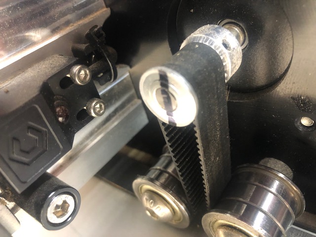
Sounds like either the pulley is loose on the left Y motor, or there is a wiring problem for that motor.
The pulley should have 2 screws, both tight, one over the flat part of the motor shaft. If you mark it like this it will be easy in the future to see if it has come loose:
If the pulley and belt are properly tight, you should probably contact support - it may be a wiring / electrical issue.
The pulley set screws are M3 (~4.75mm o.a.l.), but some folks use M3 SHCSs of a suitable length (~8–10mm) so as to be able to use a larger hex key for more leverage.