Worked out doing this previously in the Lounge as a part of another project.
Going to work through it here from scratch in the hope of making it all a bit clearer and more useful.
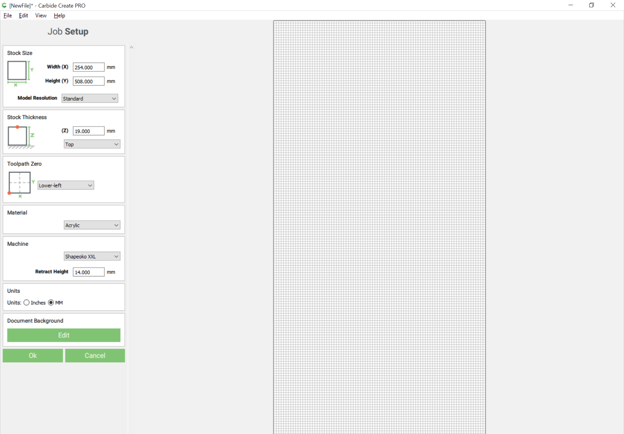
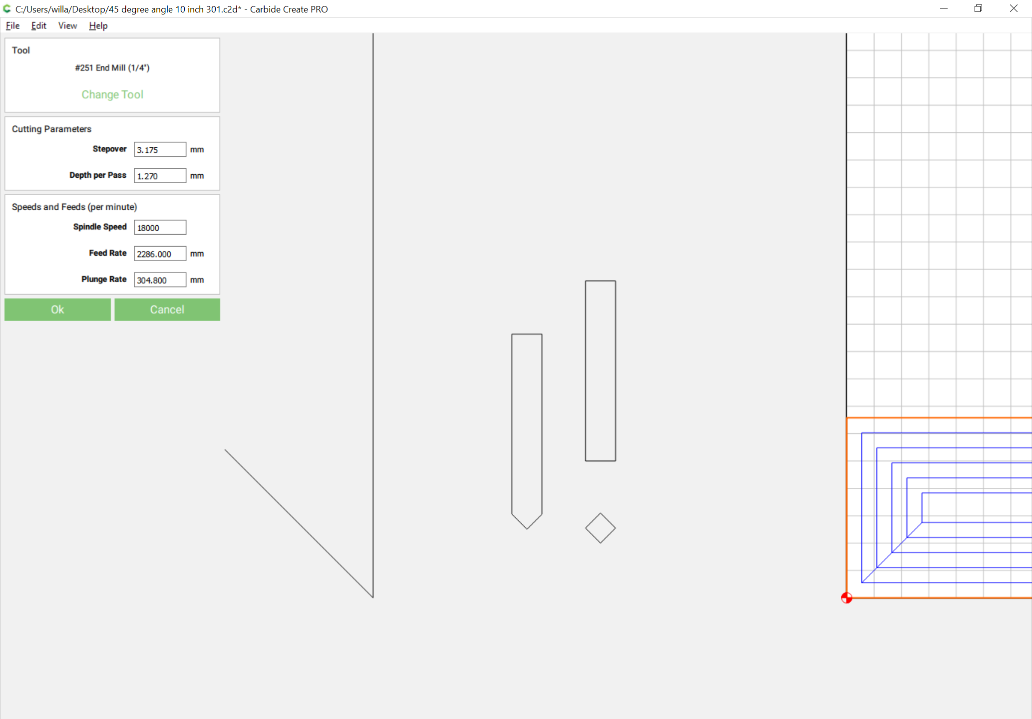
First, we are going to be cutting a 45 degree miter at the end of a 10" (254mm) wide board which is 3/4" (19mm) thick using a #301 1/2" endmill with a 90 degree taper. Origin will be at the bottom left so as to facilitate using the Probe for setting the zero.
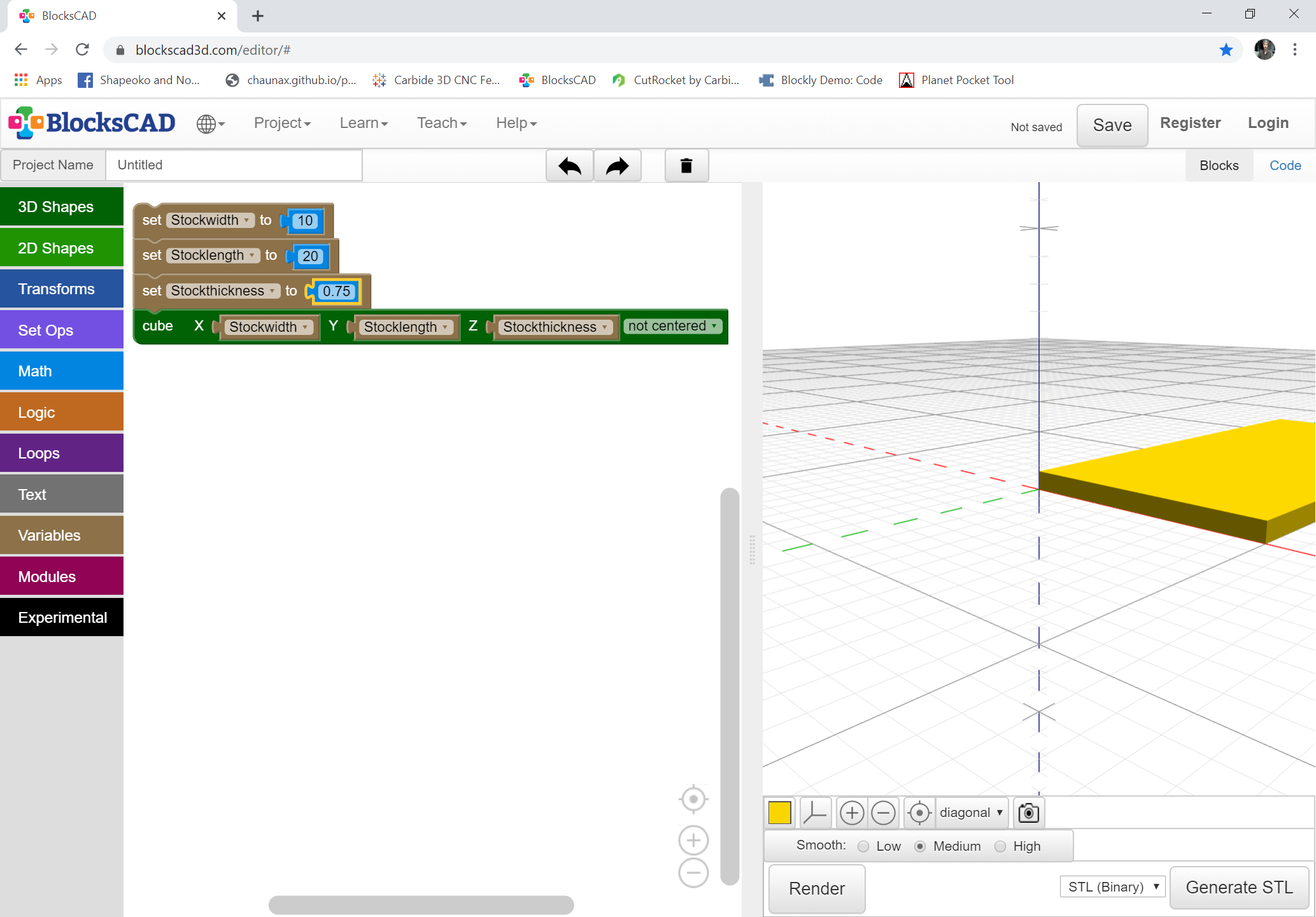
We will work this out in 2 programs: BlockSCAD/OpenSCAD (using Imperial measure so it will fit) and Carbide Create (using metric — rounding off for convenience where necessary).
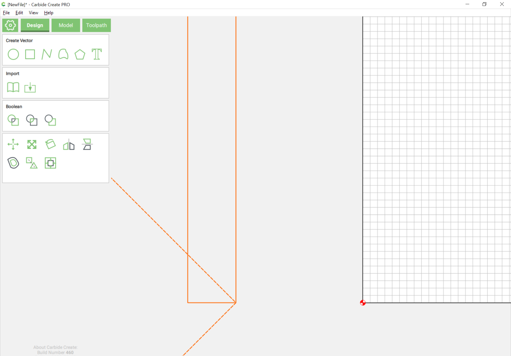
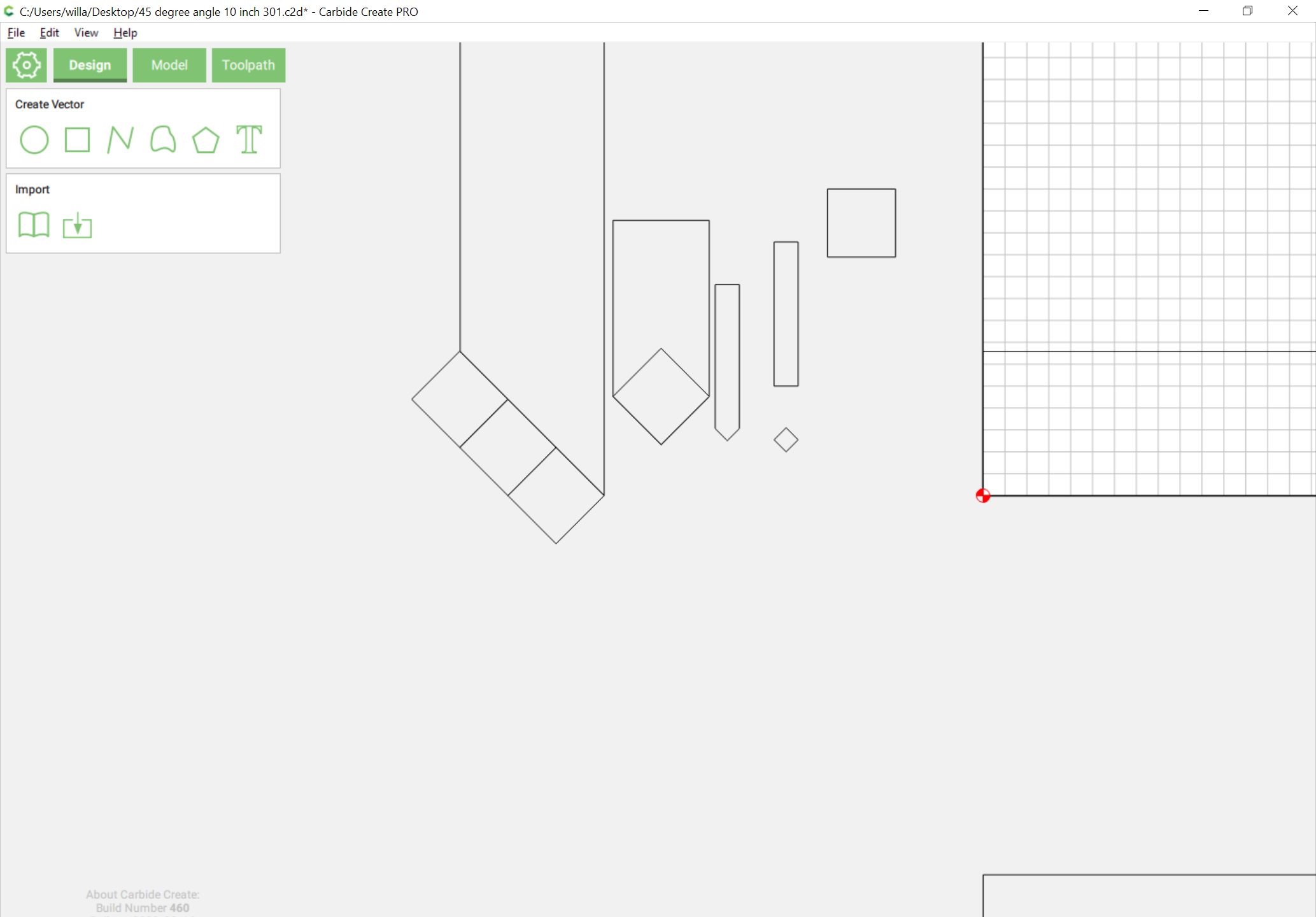
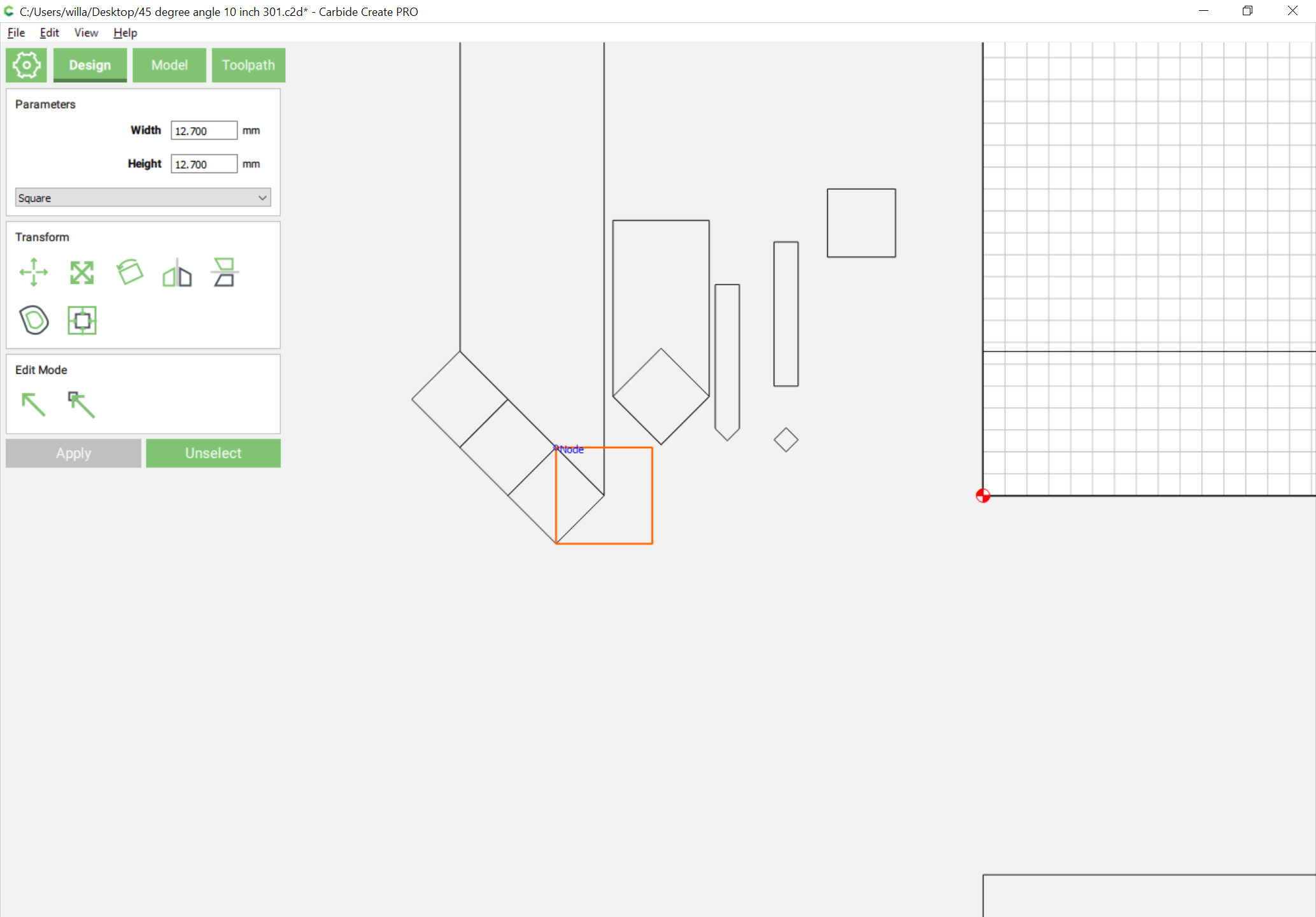
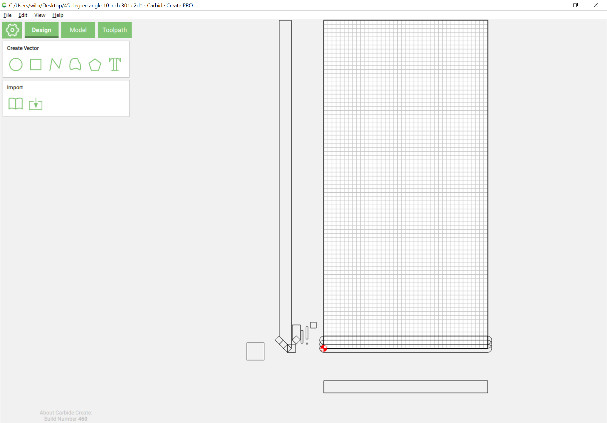
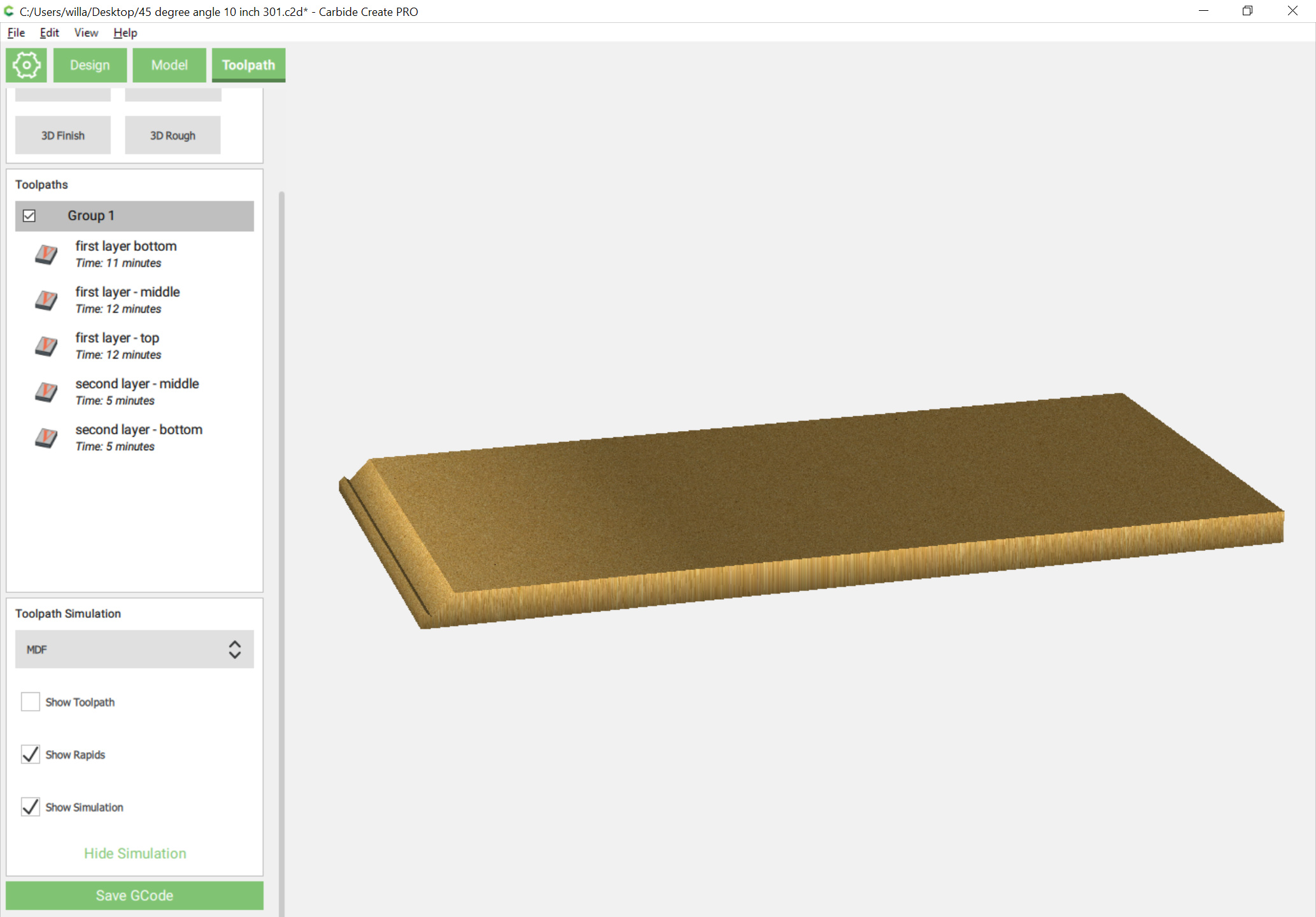
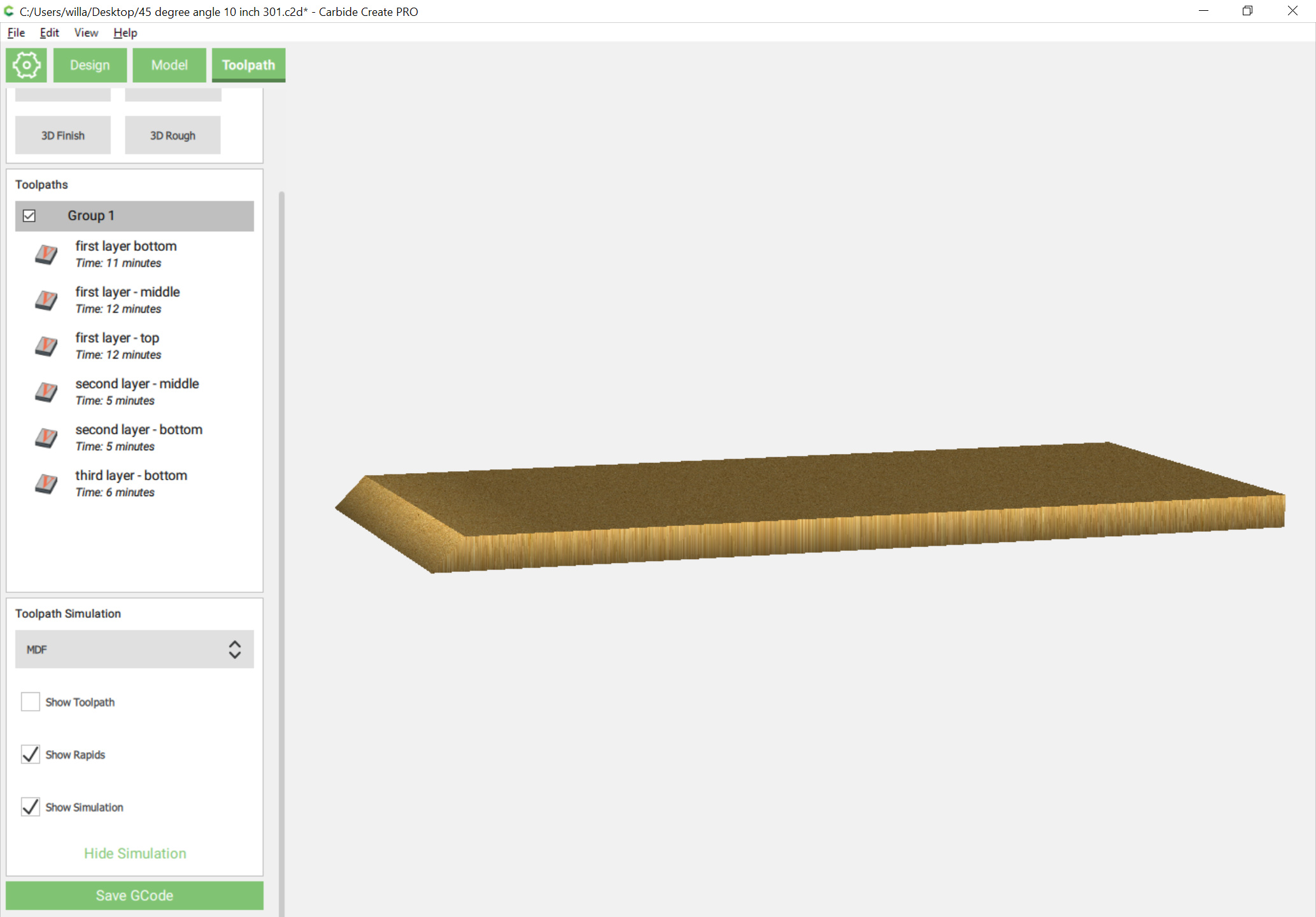
Next, we draw things up in Carbide Create so that we can understand the geometry involved, so we add side and front profile and overhead view (the latter is the stock itself) and draw in geometry to cut the miter in the side view so we’ll be able to see where things line up:
rounding that down to 1.25mm should make the math a bit easier:
19 ÷ 1.25 == 15.2
so we would need a succession of 15 rectangles which each gets narrower by 1.25mm which cut from the surface down to 18.75mm (the balance would be cut by the V endmills) — except that we are going to use a #301 endmill which only needs:
26.87 ÷ 8.98 == 2.9922049
(we’ll round)
3 passes
Except that 6.33333 repeating and the inability to accurately represent that would drive me nuts (it’s really a shame that when the Japanese chose a metric measure for type, kyu (q) it was 0.25mm — ⅓ mm would have been far more useful.
Okay,
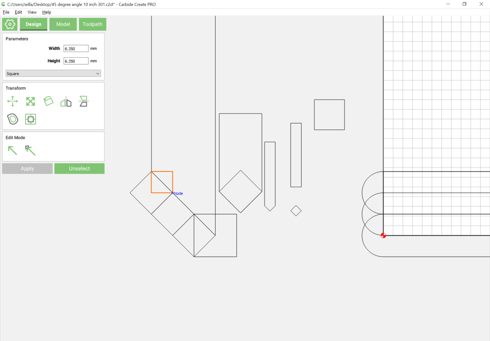
19 ÷ 4 == 4.75
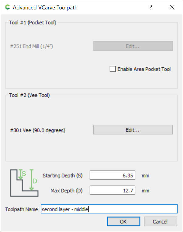
so we need 4 rectangles offset by that dimension which will allow cutting down to depths which the Advanced V carving toolpaths can then remove.