Hi All,
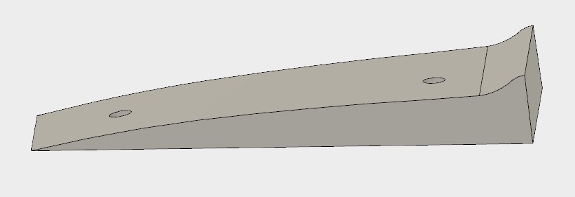
Here goes. I’m creating pieces for a mold. But the mold cavity is a bit deep, so I have sliced the file into layers.
I used Fusion 360 to create the tool paths. The material is 3/4" MDF.
The part was screwed down from underneath the spoil board, the spoil board was then screwed down to the waste board, its solid. although a bit counter intuitive.
The router bit is about 3.11mm in diameter, Carbide type.
Adaptive clearing was working really well, with a ramp on the side.
All was good.
Then the parallel cutting started offset and that was it. All stop.
I measured the holes, because they aren’t round.
The CAD file: both holes are 6.35mm in diameter.
Hole on right is 7.3 in X and 5.2 in Y.
Hole on left is 7.2 in X and 5.35 in Y.
IIRC, they should be off about .01"= 0.254mm
The holes kind of fall outside of that tolerance.
The length of the long edge in the computer measures 143.65mm.
Measured with digital calipers the length on the part measures about 143.58.
The width of the part at one location also shows an in-discrepancy, it should be close to 64.281 in the Y, but it measures about 61.51 in the Y.
About my Shapeoko 3 XXL:
Sometimes, when jogging in the X in 1mm increments, it seems to jump more than 1mm a few times. Then it seems to return to nearly 1mm increments, but larger. This is in the air so I can’t quite measure it, and because it is intermittent it is hard to catch.
I haven’t noticed that behavior in the other axis.
All help on this matter will be greatly appreciated.
So far, I have really enjoyed getting up to speed with SO3 and Carbie Motion.
I have suggestion:
One feature I would like to see on screen is the offset values, these don’t have to be editable. But it would be very helpful for comparing dimensions and making decisions.
Thank you all!
