Ever have one of those days where you were CERTAIN you were missing something obvious? I’m sure that this has been discussed, but I cannot find the proper keywords to find it in search.
I want to cut a 60-degree groove all the way through my material. I have a 60-degree bit. The material is .5 inches thick, which is SLIGHTLY larger than my bit (Freud #20-152), although it is labeled .5".
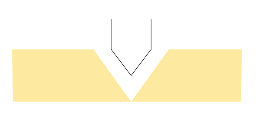
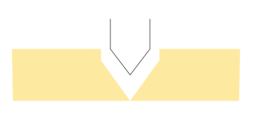
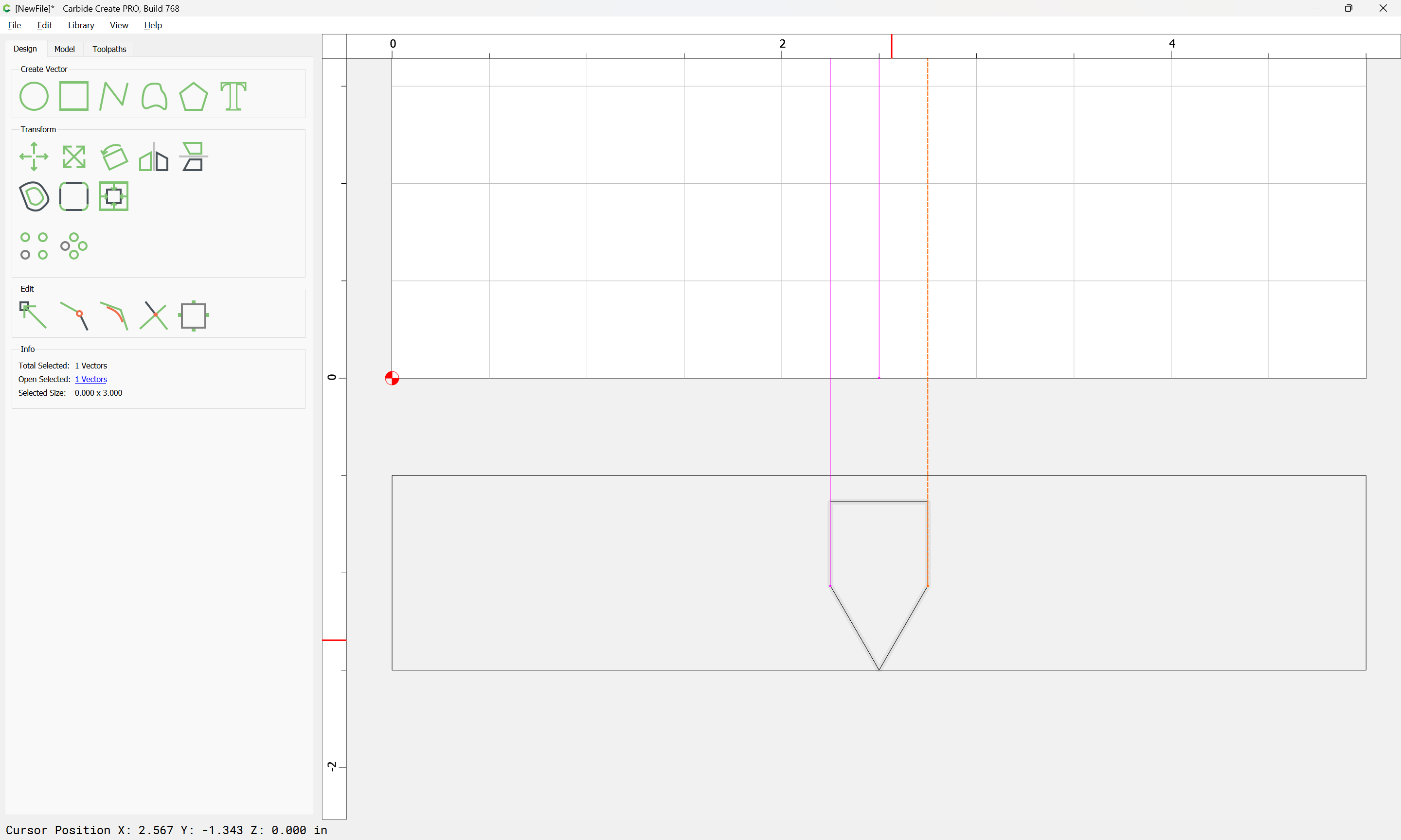
I’ve attached a crude diagram of what I am trying to do. I want to end up with 2 panels, each with a 30-degree bevel cut into their edge.
My first attempt, I just made passes over the same line, going a bit deeper each time. I ended up with a “ridge” at the top of the groove on each side, because I didn’t account account for the width of the bit.
The second time, I used Vectric (although I am asking about the technique, much more than the software… I could use any software, I don’t much care) to cut a chamfer each direction from the same line. This wasn’t ideal for two reasons (although I did NOT end up with a ridge).
It took FOREVER. I don’t think the path I generated was efficient at all.
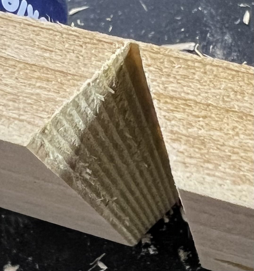
It left cut lines (see other photo) and I’m not sure whose should be there, if I’m using a 60-degree v-groove bit.
Can someone explain to be exactly HOW I am making this infinitely more difficult than it should be? And how I can make this cut, which just doesn’t seem like it should be THAT difficult, much more accurately and faster?
When I did it that way (or at least when I thought that I did it that way) I ended up with a ridge of unleveled 90-degree at the lip of the groove. (see updated diagram)
Is there some way I can avoid that with some setting I’m not setting properly?
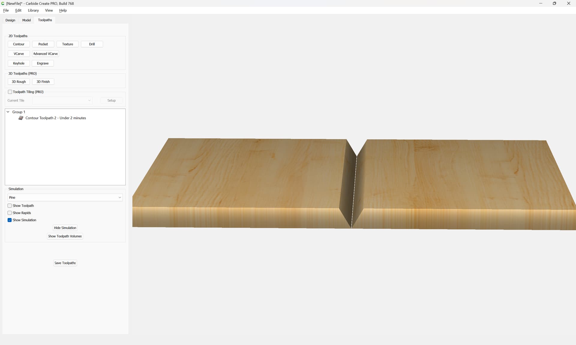
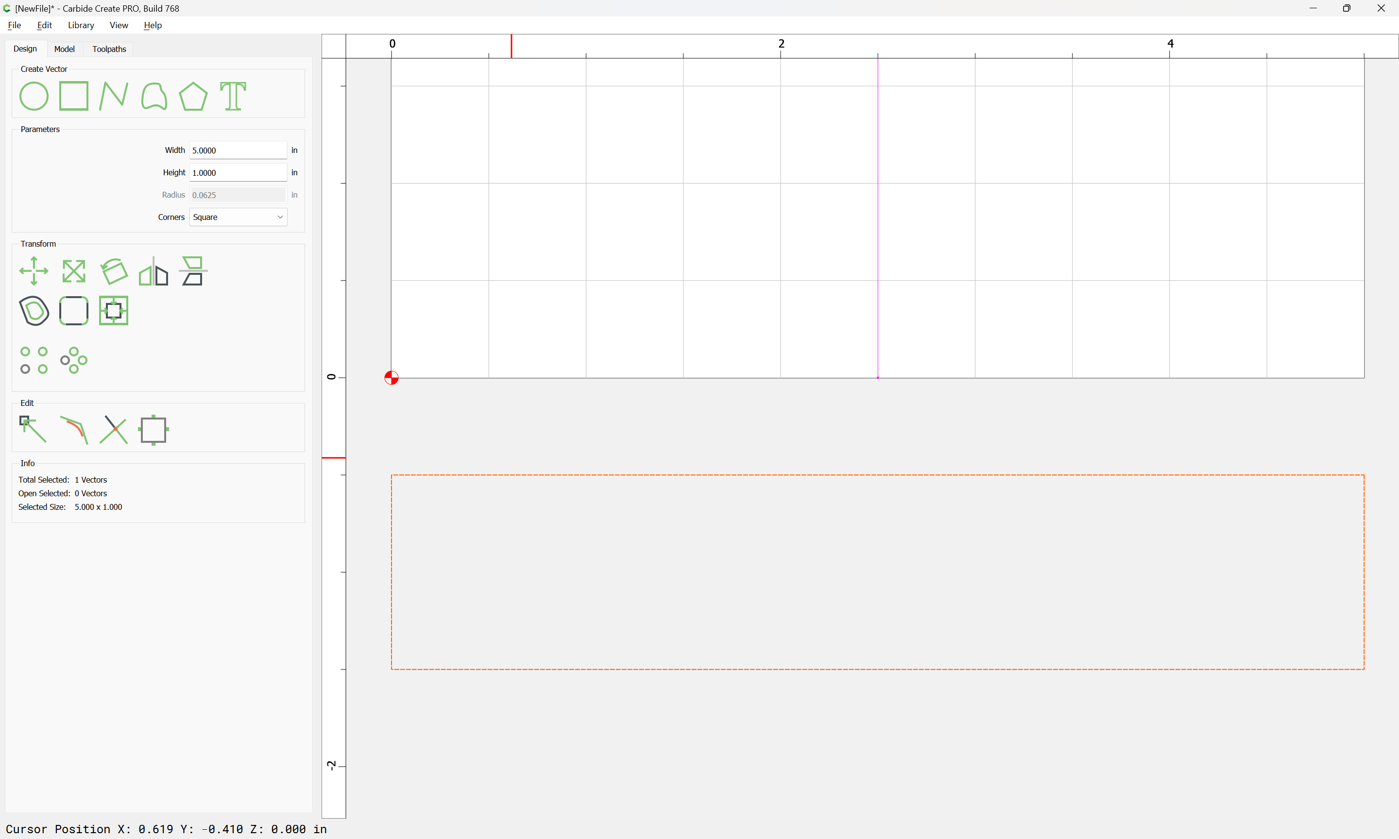
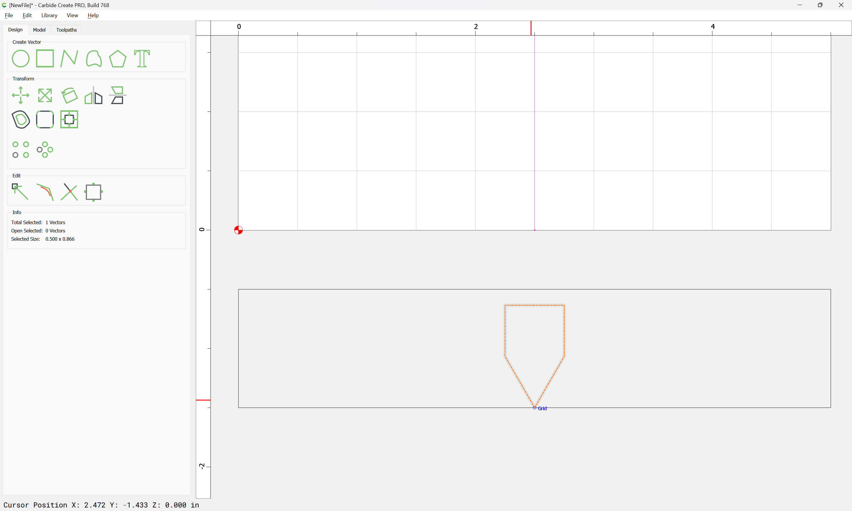
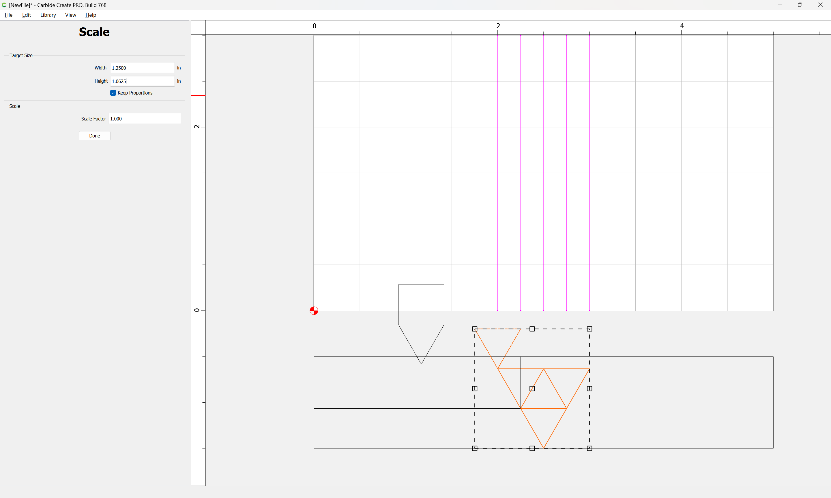
If you can calculate how wide the cut should be at the top, and draw in that geometry, then you can get a ‘full’ cut by first doing an Advanced VCarve (no clearing bit) to trace around the edges, down as far (or a little bit more) as your ‘ridge’, then do a VCarve for the rest.
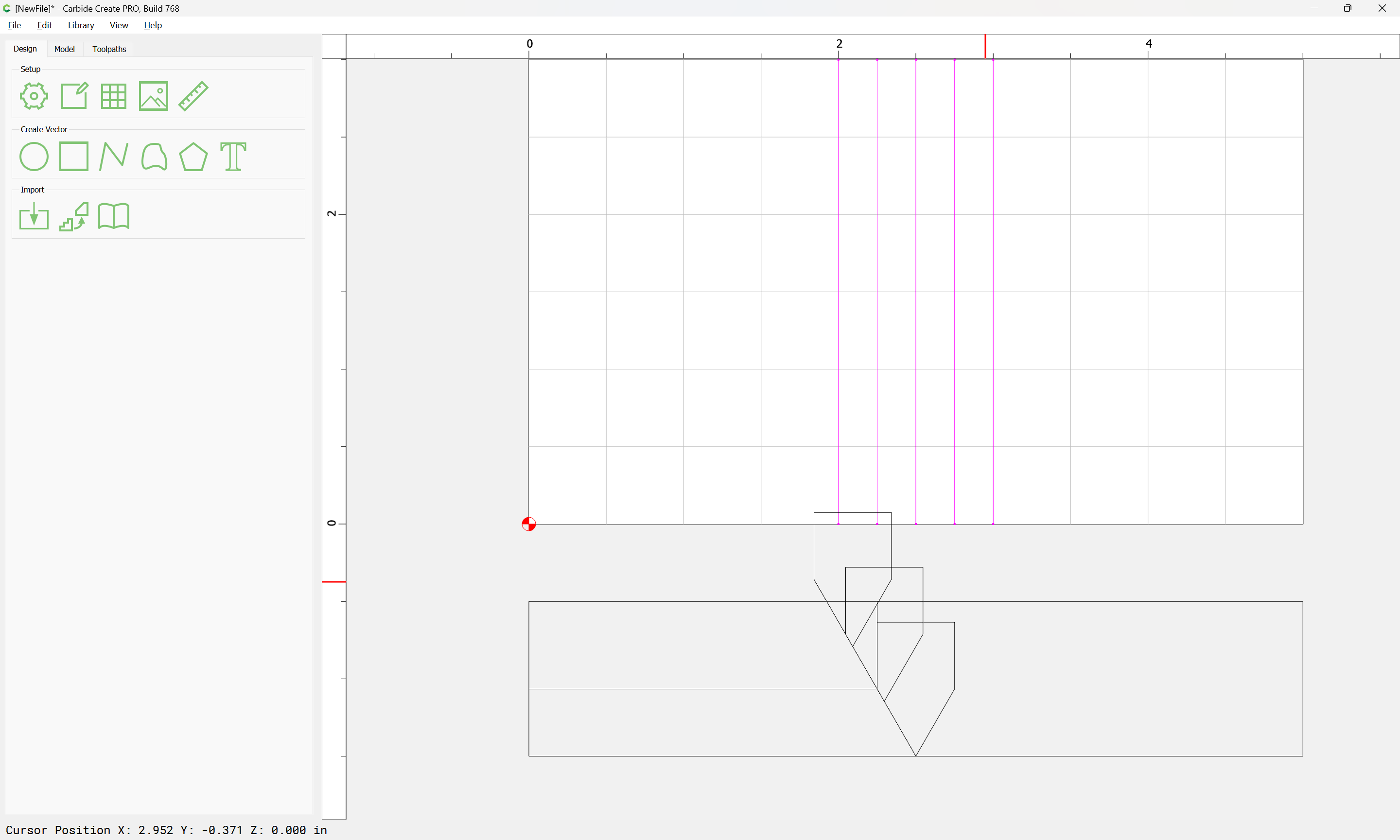
Here is a 1/2" bit on a 5/8 wide rectangle. Left to right - VCarve, full depth, Advanced VCarve 2mm, both together.
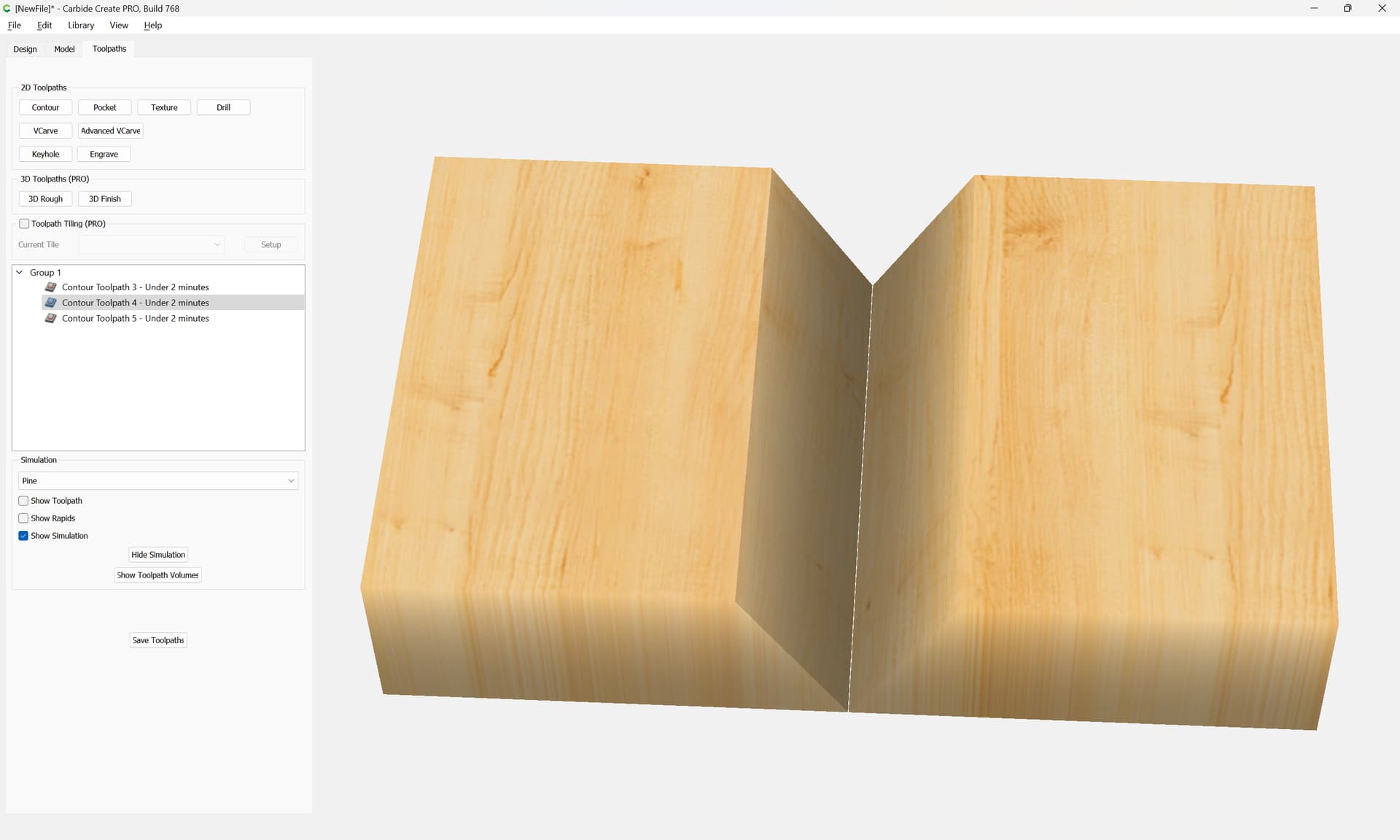
This is a sample of how I do it using 3/4" stock. By adjusting the width of the rectangle and the depth of the cut, I can achieve the results I’m looking for. Hope this helps. V- Groove.c2d (44 KB)
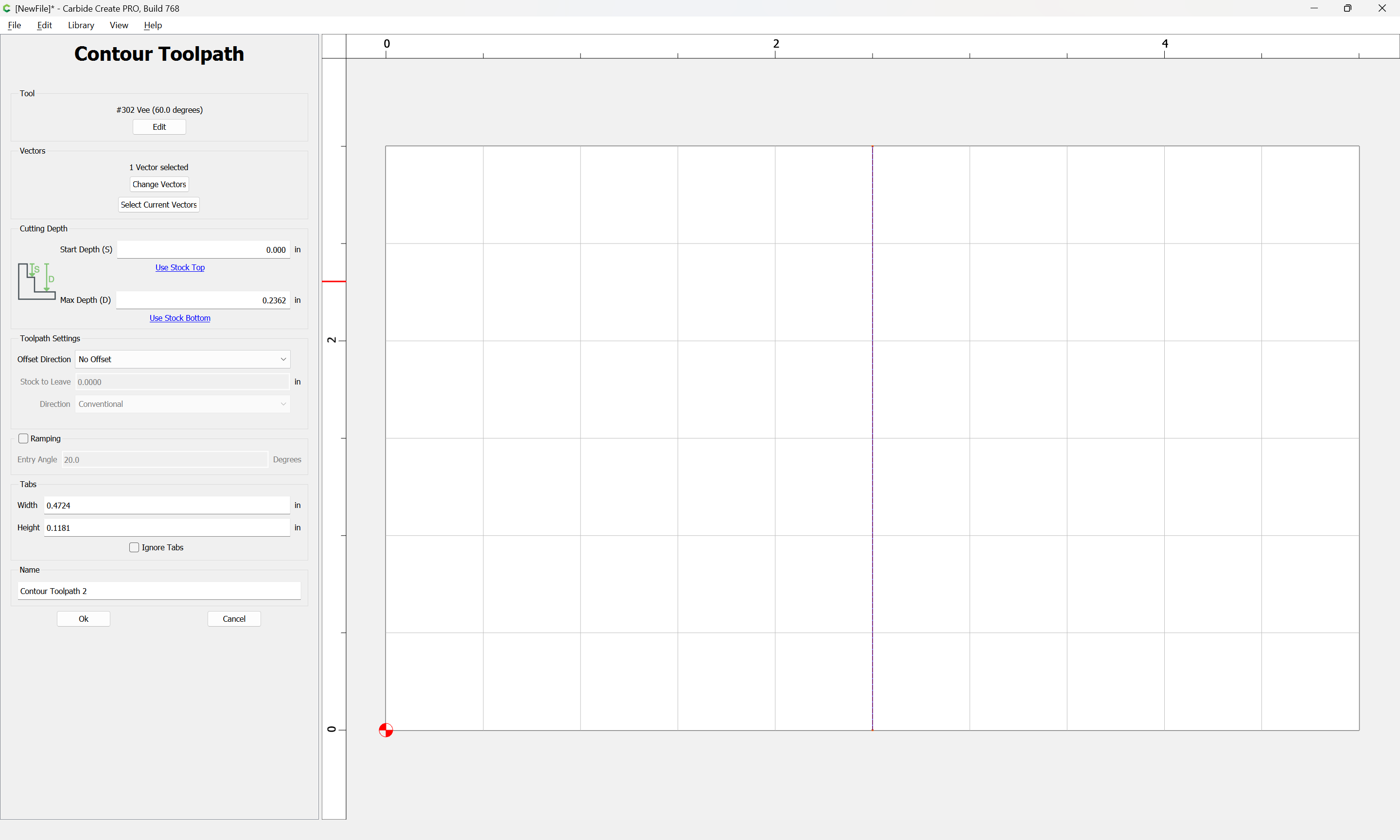
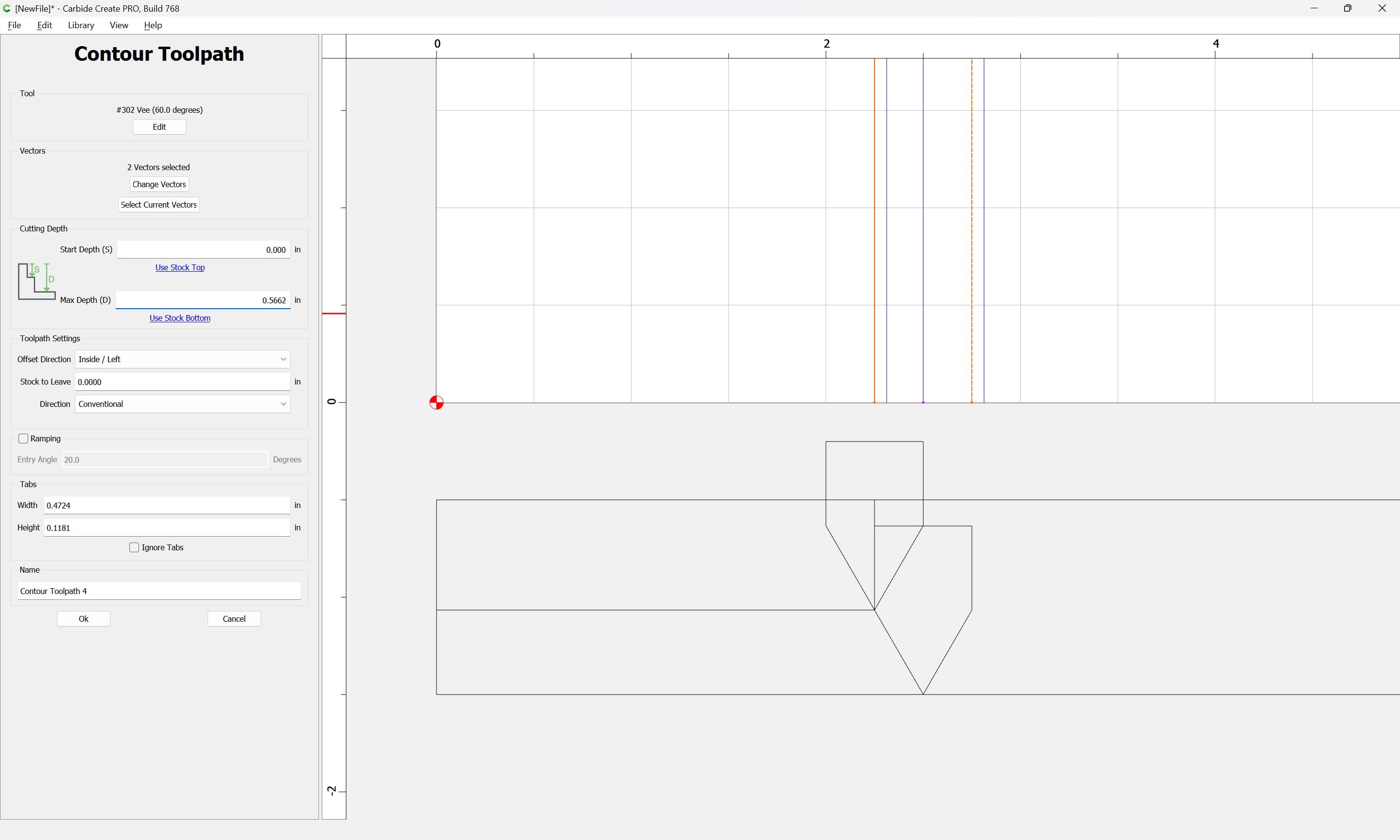
Your 1/2" 60° will cut up to 0.433" deep. In CC, you can just do an advanced V-Carve at something smaller than that to cut the top half of the groove, then another AVC, or a simple V-Carve to cut the full depth.
Thank you all for the suggestions. You definitely got me headed in the right direction. A little trigonometry helped me figure the needed width of the groove in total, the maximum depth helped me come up with the first cut, and then the second toolpath takes care of the flat spot at the bottom of the cut. Looks good in the preview, I’m about to go make some sawdust and see if it works in reality.