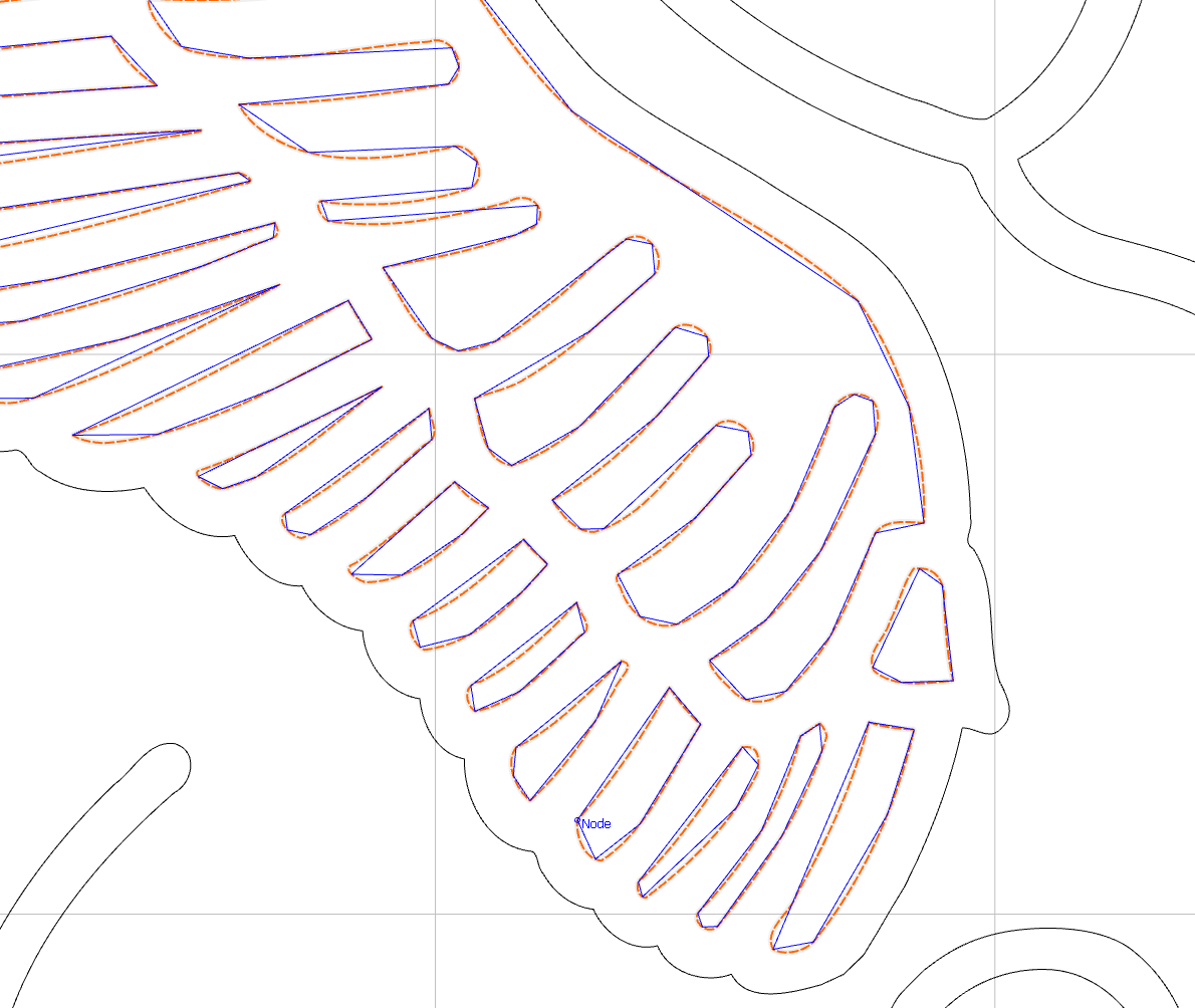
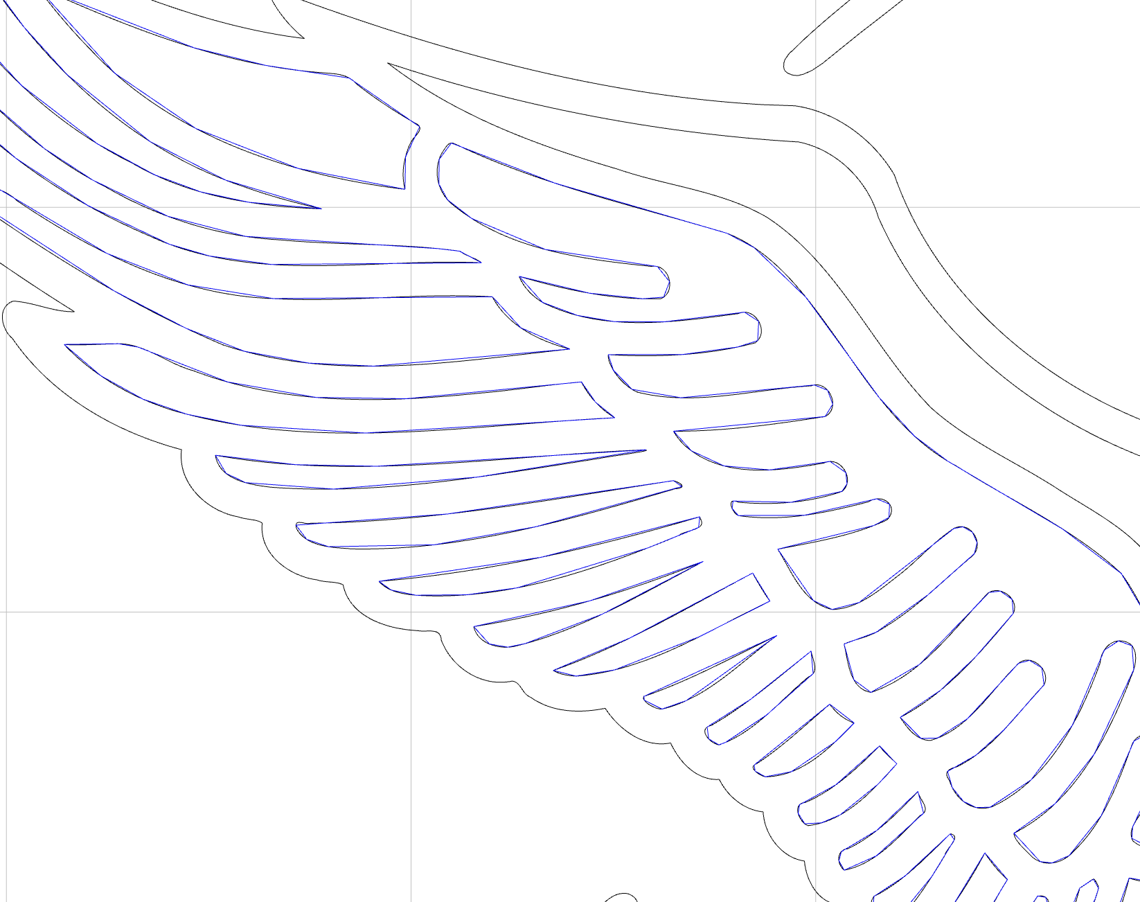
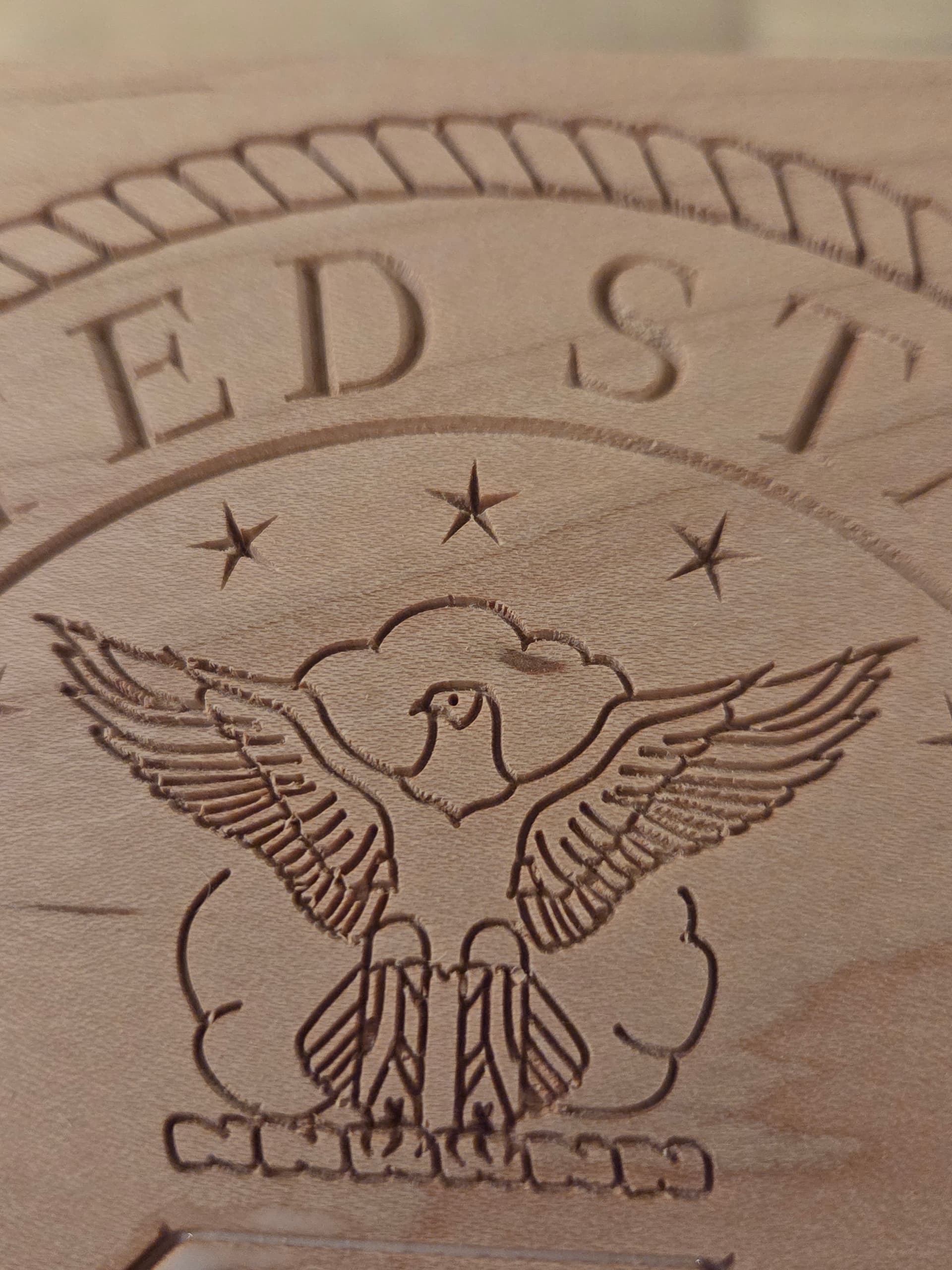
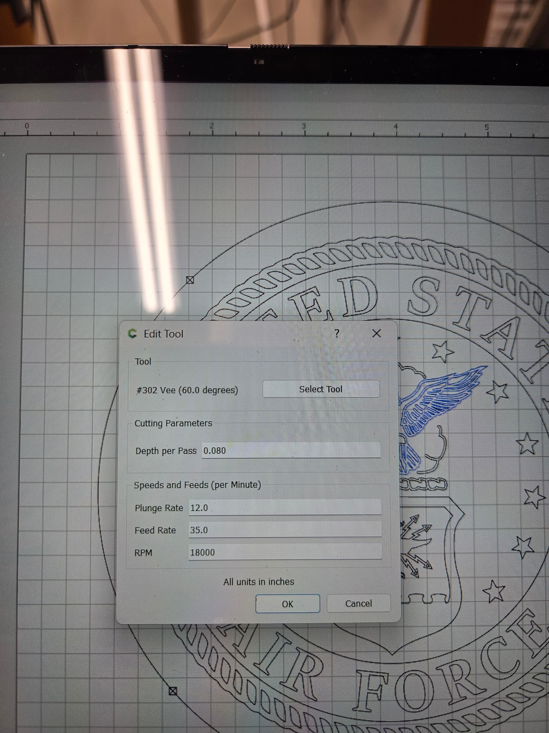
Can’t figure out what is happening but I created a contour tool path for my eagle feathers with a 60 deg vee cutter but when I see the effect on my drawing the lines don’t match the vectors. This worked fine before but in now a problem.
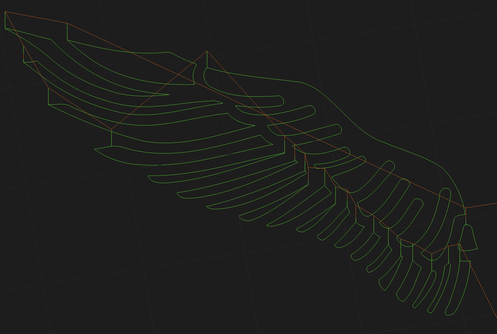
If you look at the simulation, it seems to be OK. Back in the day (2015 era?), we simplified the toolpaths in the 2D view to keep the rendering fluid. So, smaller sections can get distorted in the drawing view, even though they’re OK in the G-code.
We’ll take a look at how much we simplify the toolpaths for the next release- it’s probably OK to increase the detail now.
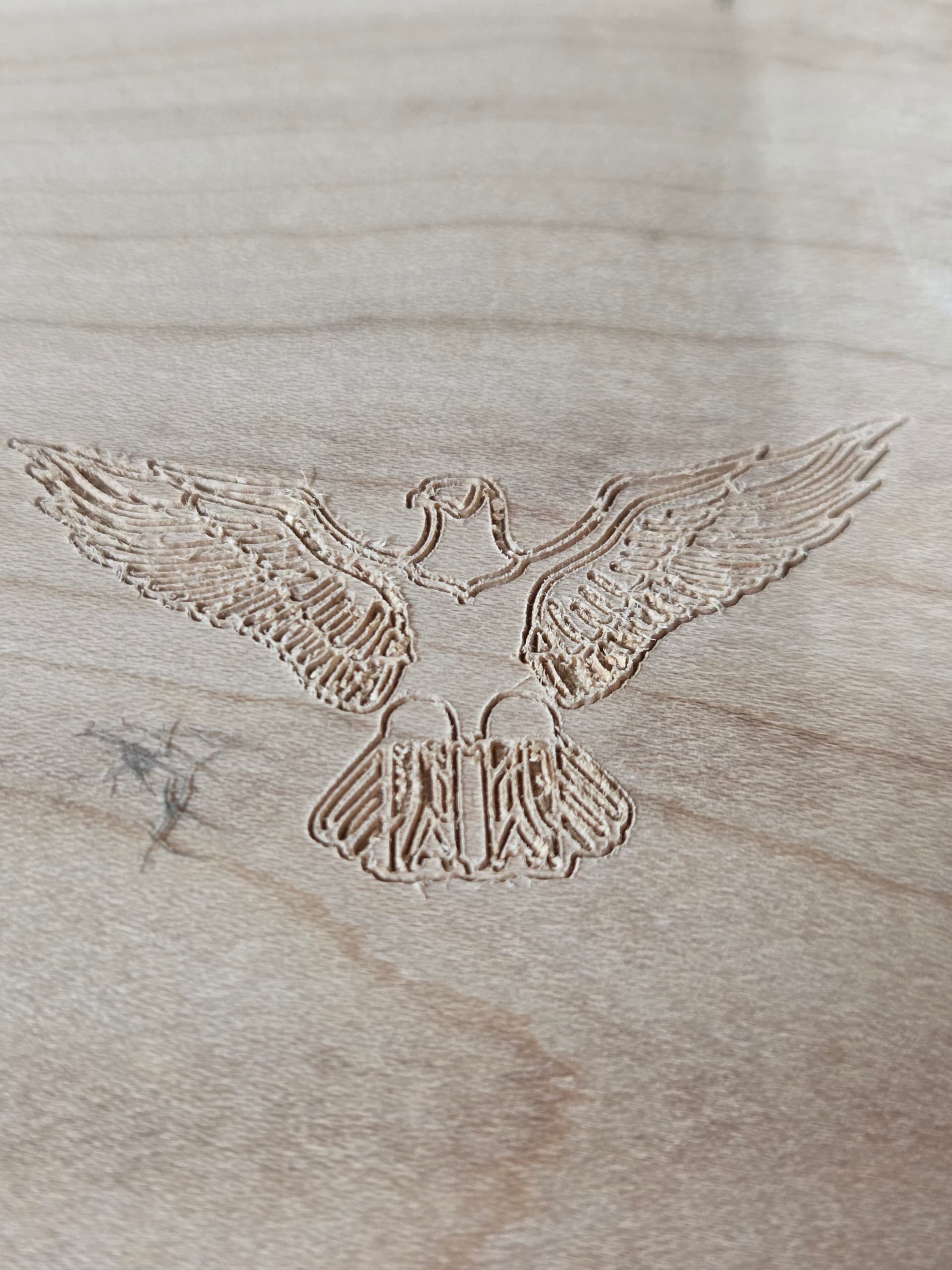
I can’t say much from the photo other than it looks like you’re getting burrs or tearout. When I export the G-code and simulate it at https://cutviewer.com, I get this, which looks OK:
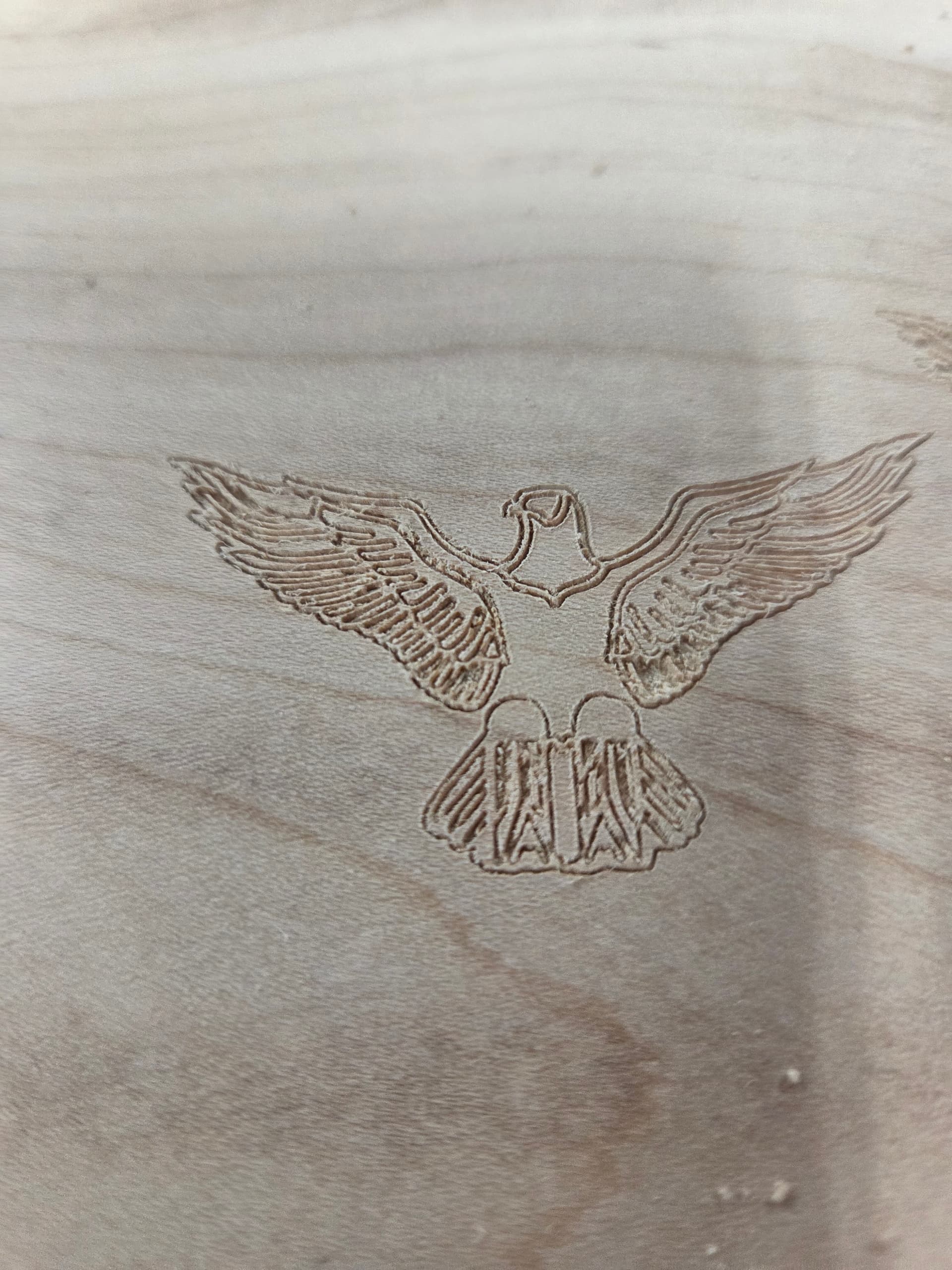
That looks like tearout to me because the actual path seems to match your design. I’d see if your cutter is getting a little dull, or try the same toolpath in a different type of wood as a test.
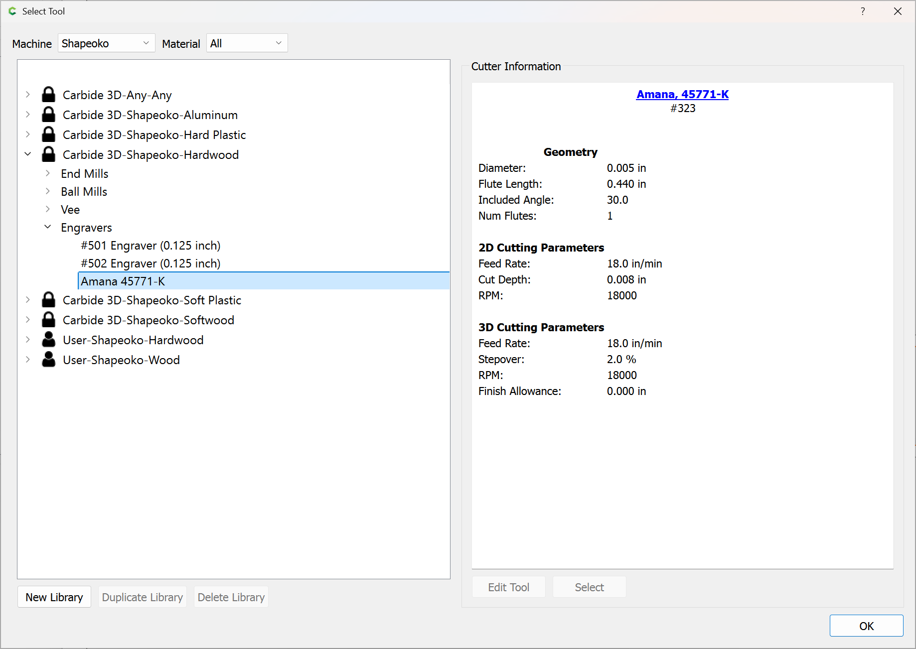
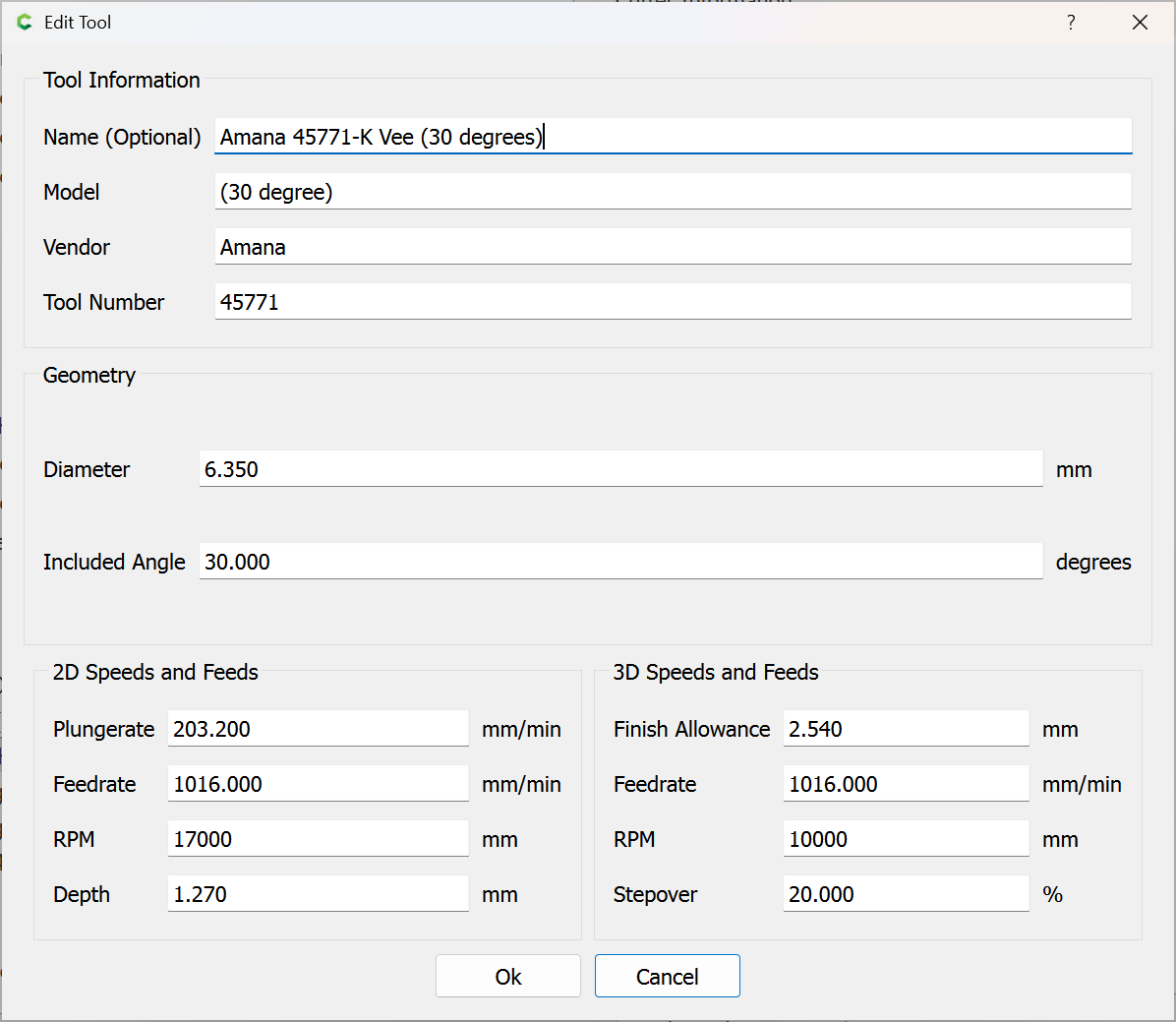
Tried doing another carve and it was a little better, but not how it was. Inspected the bit and it looks great. Lowered the feed rate and depth of cut. I am using a 30° vee cutter from CIC and since Carbide Create doesn’t have a 30° vee in their settings I had to use the 60° vee setting. Still getting some break out in maple.