I just finished initial setup on our new XL. After some familiarization with CC, CM4/GRBL1.1 and the equipment, I sketched a simple hold-down clamp in Illustrator and used CC to lay out a 2x4 grid of 8 clamps and create toolpaths.
Toolpath 1: slots for the T-bolts
Toolpath 2: profiles for the clamps
The toolpaths previewed properly so I exported gcode and ran the project. Toolpath 1 ran perfectly. Toolpath 2 cut only 3 of the 8 clamps, then retracted the Z and parked nearby. There was no disconnect and no error message.
I was able to create a new toolpath for the remaining clamp profiles and finish the job, but that leaves the question: why did my XL stop after completing only 3 profiles?
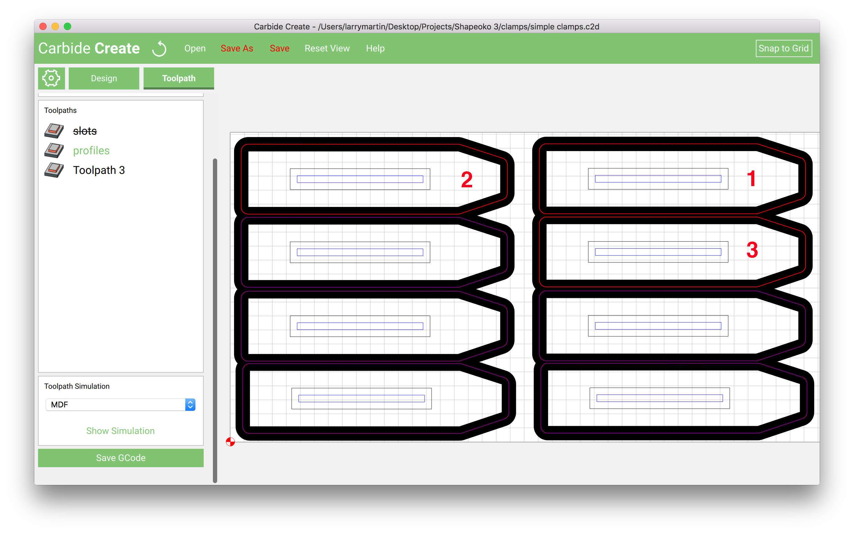
This may be a clue: see the screen capture below showing the visualization of the profile cuts. If you inspect it you can see that:
• All of the profiles are black, indicating through cuts.
• There are red lines in the middle of the black profiles, tracing the actual path of the bit.
• But only 3 of the 8 red lines are heavy. The remaining 5 are very light.
The 3 profiles that did cut are numbered in the image in the order that they cut. They are same 3 profiles that were indicated with heavy red lines.
I found threads in the forum about stopped cutting but all seemed to focus on equipment (disconnects, EMI, cables, electronics) and this seems more likely to be a software issue.
I’m new to SO and CC and don’t know where to start solving this. Any suggestions?
One can easily wind up with a mis-match in what one is expecting Carbide Create to cut and what it is actually planning on cutting by changing the selection before completely confirming the toolpath.
If the G-Code doesn’t approximate what the .c2d file is previewing, please send the pair of files in to support@carbide3d.com and we’ll do our best to have a developer look into it.
My memory is that I selected all 8 parts and created a toolpath for them.
Still, you could be right, Rich. I’m all too familiar with operator error, especially when I’m the operator.
But if I messed up and only selected 3, why do all 8 parts show the black outline indicating cut through, and why does the simulation show all 8 parts being cut? How did that happen if I only selected 3 of the 8.
There are several reasons why they show up in black (still)…but the leading cause is (probably) software error OR another operation is active. In the future, pay close attention to those (hard to see) orange lines.