Don’t know if it’s been mentioned or asked, but on this 1/8" end mill how long is the actual cutting length? The C3D #102 .125" Flat Cutter has a cutting edge of 1/2" I believe. To be cutting 1/2" material you’re right at the edge of that length and running out of room to evacuate chips. The speeds and feeds are off as has already been mentioned, but you might also look at something like a single flute 1/4" bit instead of the 1/8" bit.
Quick response-- qualifying a code build and even at 5% speed, the machine will do a lot of damage quickly…
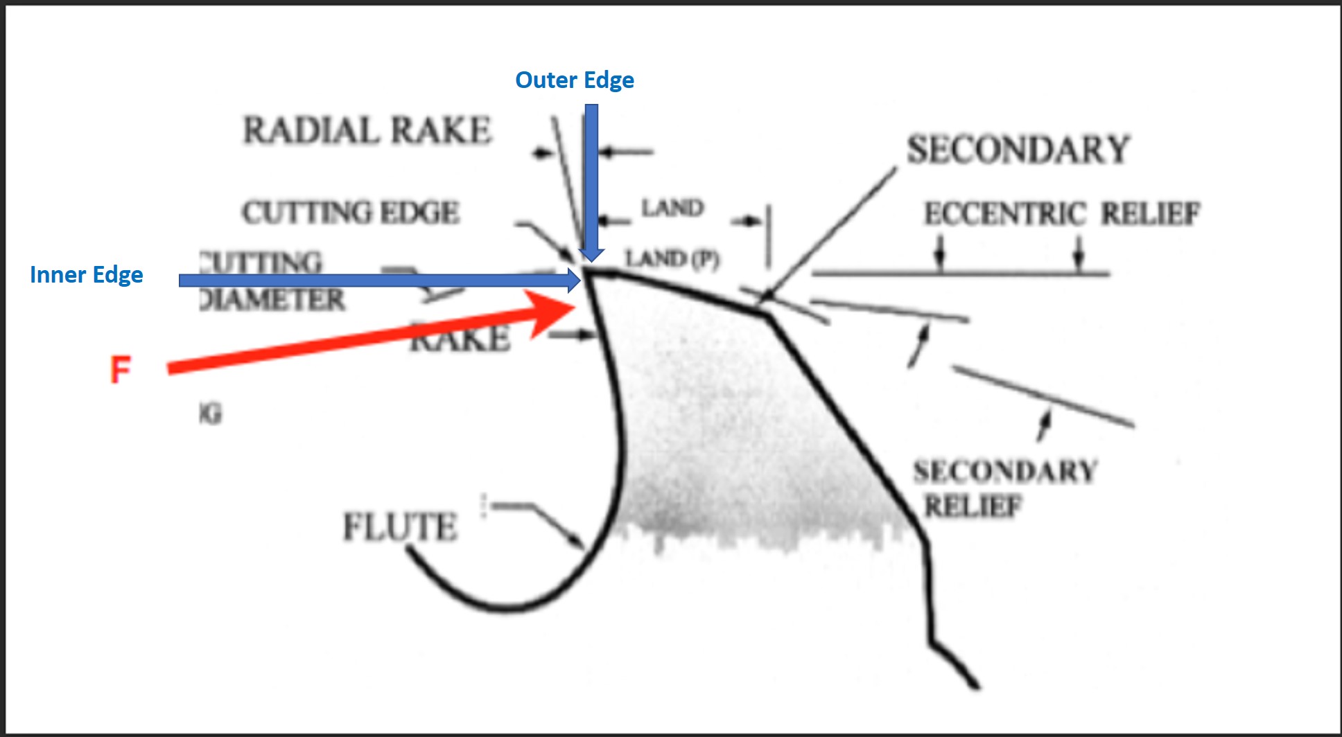
Outer edge? Inner edge? Do you mean the clearance angle? That is needed to prevent rubbing. Too much feed per tooth and this will rub on the stock (you may have experienced this trying to force a twist drill too fast). Otherwise, this is not a “source of heat”…
Some heat will get into the workpiece. But most ends up in the chip. A considerably amount does not mean most of the heat, only that you can’t ignore it (barring running the tool very, very wrong).
For practical purposes, ALL of the work done by the tool goes to heat at the tool (an insignificant amount becomes kinetic energy moving the chips), either from friction or deformation/fracture of material. It has nothing to do with efficiency.
Heavy chips are not necessary due to the heat going into the chip. Too light a feed will give rubbing due to material deflection, and with most plastics, this is a moderate feed, as they are quite elastic, compared to, say, steel. Rubbing heats the base material and tool. This has a number of unpleasant results, including melting of the material. Too light of a feed tends to give fine chips that pack and jam in the flutes and melt in easily. Under similar heat, heavier chips tend to clear better, within reason.
No where do I say or imply that high chip loads are necessary because most of the heat (under reasonable cutting conditions) ends up in the chip. I did say that you need sufficient chip thickness for them to clear and for consistant cutting without rubbing.
If this discussion had included forced cooling and chip evacuation (liquid or gas), other things would have come in, but it did not. You don’t need to LIKE that, in the situation under discussion, most of the heat should go with the chip (I will elaborate: with the ductile and malleable materials being discussed), but that is what it is.
Violating one of the most basic principles of thermodynamics? Woodworkers (@WillAdams and others), have you ever seen or heard of chips/sawdust burning, scorching, or catching fire on anything other than an improperly operated CNC machine? Have you ever seen or heard of the workpieces being scorched?
Here’s what I meant by outer and inner cutting edges. Notice how much more friction inducing cutting area engagement occurs on the outer edge than the inner edge.
“For practical purposes, ALL of the work done by the tool goes to heat at the tool (an insignificant amount becomes kinetic energy moving the chips), either from friction or deformation/fracture of material. It has nothing to do with efficiency.” I suspect that, with most if not all materials, most of the work goes into fracturing the material. But do agree that an insignificant amount goes into kinetic energy moving the chips. Unfortunately, fracturing the material can be an inefficient process, so heat is generated.
“No where do I say or imply that high chip loads are necessary because most of the heat (under reasonable cutting conditions) ends up in the chip.” Sorry, I guess I misinterpreted your intended contribution to this discussion!
" You don’t need to LIKE that, in the situation under discussion, most of the heat should go with the chip (I will elaborate: with the ductile and malleable materials being discussed), but that is what it is.
I’ll leave it at this."
For me, its really not a matter of “LIKE”, I’m just trying to understand your point of view.
@Julien, @Vince.Fab
The proof is in the pudding. Why not use your IR cameras to determine what really happens?
Agreed, it’s only when things go wrong that there is melting or fire or smoke.
My understanding is this:
endmill and stock start out at ambient temperature
as cutting occurs, friction between the endmill and the stock/chip EDIT: and chip deformation as noted by @The_real_janderson creates heat
this heat is divided between the chip and the stock and the endmill in accordance with the characteristics of each EDIT: or formed in the chip and the stock
some cooling happens as the endmill edge leaves the stock material and spins in open air
if/once the endmill heats up beyond ambient temperature it then has additional thermal energy which presumably is transferred into the stock or the chip, shed into the atmosphere, or retained in the endmill (EDIT: with some being transferred into the collet and the body of the spindle/trim router)
I think that covers everything (corrections/additions welcome) — I’d love to see the physics of it all written out as mathematics which we can examine and verify.
I recently bought one of these from Amazon to cut thick Baltic birch. It’s a 1/8" diameter 2 flute endmill with a 1" cutter height. It requires 1/2 the MRR, power, and force that a 1/4" endmill would require for cutting. Lonnie (if still online?) should minimize cutter stick-out though! Maybe the primary problem (OP) is that the bottom 1/32" of the endmill being used is worn out?
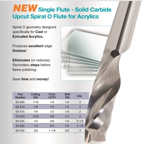
Note that it’s not only BW who advocates thick chips in plastics, I just stumbled upon this Onsrud site, they recommend for a chipload of 0.004" to 0.012" when milling plastics without coolant.
I have tried HARD to follow the different positions stated above, and I am certainly not in a good position to argue one way or the other, but if I take a step back from the details what I hear is that friction and deformation are causing heat (nobody disagrees here right?), heat needs to go somewhere, some of it in the chip and some of it in the workpiece, but anyway the surface layer is just a lot of future chips, so in the end what matters is how fast one can get hot material out of the way, be it with lots of very thin chips or fewer thicker ones. @WillAdams told it better than I just did though.
So that really was BW? Are you sure that they’re not the maximum recommended chip loads like their other chipload charts. I can’t get past the following page, what am I missing?
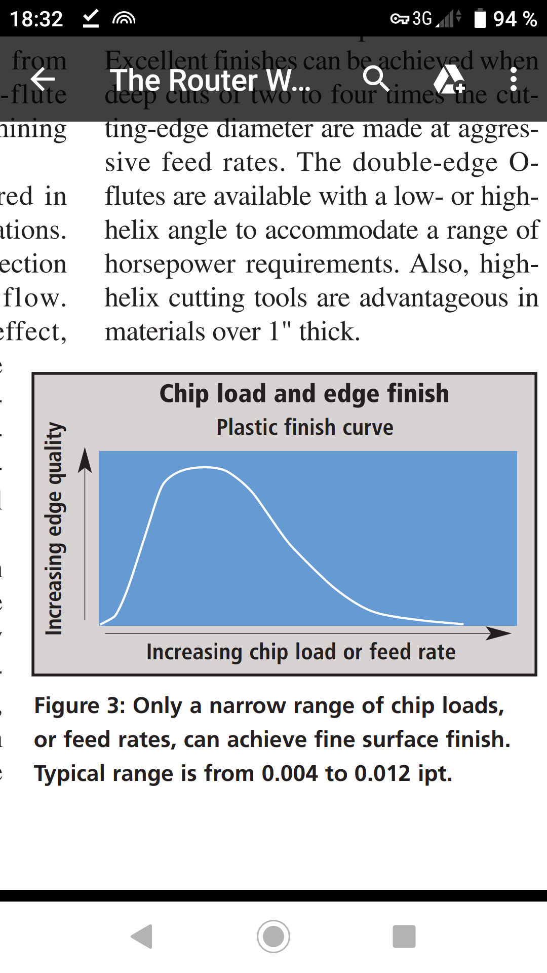
OK, here’s what I found at“In plastic, there is a very narrow range of chipload to maximize finish and cycle time. Since finish seems to be one of the most important factors in machining plastic, the range falls between .004 and .012. However, finish is always a personal decision and some applications may warrant a larger chipload at the expense of finish to increase productivity. In other words, do not be limited by the recommended range, but use it as a guide.”
Cool -thanks! Here’s some more of the text “Chip Load
Once the correct tool geometry is chosen, the proper chip load is the next consideration. In mechanical-plastics machining, the recommended chip load range is 0.004 to 0.012 ipt, which results in an excellent finish and acceptable productivity rates (Figure 3). This narrow range imparts the finest finish through the continuous generation of properly sized or curled chips. Inadequate chip load can lead to knife marks, which adversely affect the finish. O-flute tools with a high rake and low clearance help eliminate knife marks by slightly rubbing the part during machining." Sounds like friction on the outer cutting edge bevel is used to melt/smooth the workpiece with their specialized endmills. Acrylic cuts real nicely with a laser too!
Could it be that some manufacturers only provide cutting recommendations because they’re designed for that particular speed? The 1/8” endmill recommendations would result in feeds of 50- 75 IPM, cutting forces of ~3.2 - 4.7 lbf, cutting powers of ~ 29 - 44 Watts, and MRRs of ~0.78 - 1.17 cuin/min. Doubling the speed to 25,000 RPM would enable a doubling of the feed rates and MRRs while maintaining the same forces and cutting powers. Halving the chiploads by reducing the feedrates to 50 - 75 IPM at 25,000 RPM would reduce the recommendation’s cutting forces and powers by a factor of 2.
[quote=“Julien, post:28, topic:15778”]
what I hear is that friction and deformation are causing heat (nobody disagrees here right?), heat needs to go somewhere, some of it in the chip and some of it in the workpiece, but anyway the surface layer is just a lot of future chips, so in the end what matters is how fast one can get hot material out of the way, be it with lots of very thin chips or fewer thicker ones. @WillAdams told it better than I just did though [/quote]
IMO the best way to cut acrylic is to minimize heat generation by minimizing chiploads (unless something like Aluminum HSMing occurs.) Since the melting temperature of acrylic is much lower than Aluminum, any HSMing would occur at a much lower endmill temperature.
It appears that early on in this discussion BW wisely gave up on his “deformation” argument. All of the heat is caused by friction. It tries to melt the cut edges but virtually none of it is conducted (goes) into the plastic. Any residual heat will be conducted into the endmill. Here’s plastic experts’ recommendations for cutting/routing acrylic. “The spindle speed required to produce a satisfactory edge is 10,000 to 20,000 rpm. A smooth, constant feed rate of 10 to 25 feet per minute is required to prevent localized heat buildup, which will cause smearing or gumming of the cut edge.”
This corresponds to 120 to 300ipm, make that 200ipm max on the Shapeoko. They do not explicitly specify number of flutes, but they advise 2 fluted tools so let’s assume that. This gives a min chipload of 120 / (2 x 20.000) = 0.003", and max of 200/(2x10.000) = 0.01", so relatively thick chips and quite in line with earlier discussions and with Onsrud [0.004" to 0.012"] recommended range ?
I don’t disagree that the theory calls for lower friction to get lower heat and that thin chips are a way to get that, but many, many people have experienced good cuts in plastics with thick chips, as long as one is feeding fast enough. Maybe the chipload does not matter so much as the fact to get that tool moving out of there, fast?
Apparently they were referring to 2 flute endmills, so you’re right. But, what’s “good for the goose [pro machines] is[n’t necessarily] good for the gander [Shapeoko users]”. Higher than necessary chiploads require higher than necessary cutting forces and produce more heat.
“I don’t disagree that the theory calls for lower friction to get lower heat and that thin chips are a way to get that, but many, many people have experienced good cuts in plastics with thick chips, as long as one is feeding fast enough. Maybe the chipload does not matter so much as the fact to get that tool moving out of there, fast?”
Many of those people apparently use only the tips of their endmills, causing them to wear out prematurely. Is that because of BW’s misguided recommendations or is it compensate for the extra force required to achieve the high chiploads?
Lower chiploads = lower heat = better results.
“Because it is a thermoplastic material, Plexiglas® acrylic sheet softens when heated to its forming temperature. The frictional heat generated by machining tends to soften the material in the immediate vicinity of the cut, and causes gumming and sticking of the tool or tearing of the plastic if excessive heat buildup occurs. When proper speed,feed and cutters are used,machined Plexiglas® acrylic sheet surfaces will have an even, semi-matte surface, which can be brought to a high polish by sanding and buffing”
Phew, I leave on a short trip and come back to a lot of heated discussion here. I’ll answer your initial question to me first:
Thinking in chip per tooth provides a more holistic approach to milling materials. It combines both rotation speed, and flute count. This makes translation to other materials and machines much easier since you don’t need to ask for 3 variables as it already accounts for that. When someone tells you they cut maple at 0.05 mm/tooth, it contains more information than that they ran at 500 mm/min and yet takes approximately the same amount of characters to write out. This does still not tell the whole story (ADOC, RDOC, endmill diameter, etc.) but it’s a step in the right direction.
As for all the other conversation, I’ve done tribological (two materials rubbing against each other) calculations at work more for static considerations but similar concepts at at work here. Let’s consider the thermal energy balance:
(My primary source of non-experiential information is an excellent paper by Abukhshim, Mativenga, and Sheikh on “Heat generation and temperature prediction in metal cutting: A review and implications for high speed machining”)
Created sources of energy
Friction from the endmill rubbing the material (kinetic energy into heat energy)
Shearing heat from the endmills shearing through the material (kinetic energy into heat energy)
Since those are the two sources of heat energy in milling, let’s talk about what happens to it. There are 3 possible options here:
It goes into the endmill
It goes into the chips
It goes into the substrate
Let’s talk about each of these.
1 - It goes into the endmill
This is a significant portion, although smaller than what people believe. In metals, roughly 10-30% of heat generated from cutting transfers into the tool. Given the lower thermal conductivity of plastics (by around 2 orders of magnitude [steel = 16 W/mk & PMMA = 0.25 W/mK]), that number is easily less than 10%. This means that most of the heat does not make it into the endmill but instead is transferred elsewhere.
2 - It goes into the chips
A common belief, and although real, is not the largest component. Let’s get into a breakdown of how cutting happens.
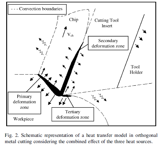
Shown below is a diagram of a tool cutting material. There are primary, secondary, and tertiary heat generation zones. In our common vernacular, we think of the primary zone as the shearing/cutting zone, the secondary zone as the friction/rubbing zone, and the tertiary is rarely mentioned in hobby machining at all. Heat generation into a chip happens in the primary and secondary deformation zones. The secondary deformation zone accounts for roughly 20-35% of the heat generation that the primary zone does, and given what we mentioned in section 1, most of that heat goes into the chip. Now, this is a substantial amount of heat that a small chip has to hold and not melt onto the endmill so the heat transferred into the chip must be less than what it will take to get the plastic to its glass transistion temperature (where it becomes very soft). If you are getting your flutes full of melted plastic, you need to speed up to increase the heat capacity of your chips to resist melting.
This is the last place the heat can go and accounts for the majority of heat generation in plastics especially. The heat generation happens in the primary and tertiary deformation zones, and given how plastics have much larger plastic deformation zones than metals, the shear-heating within the material is large since not only is the area by the chip being heated but material a few millimeters in is being heated as well due to thousands of deformations per second moving the polymers around. The heat generation here is at least 50% of the total heat generation and most certainly higher given the low material removal rates we run at and plastic material being cut.
The big importance to all this is that the amount of heat generated and put into the substrate (to contribute to heating and potential melting) is dependent on the material removal rate. The more material is removed and heat pulled away by chip removal rather than substrate heating, the less likely you will encounter a situation where your substrate begins to melt. This makes us hobby machinists need to push our comfort zones and actually take larger chiploads in plastics to avoid problematic situations.
Source: “Experimental study of the temperature field generated during orthogonal machining of an aluminium alloy.”
P.S. I didn’t touch on chip removal, friction affects from coatings, and more here. Please, look up published articles on these things. Nothing we are discussing here is new within the machining community and there is a lot of good science behind it all.
My comments above are in direct contradiction with @gmack’s comments a couple up where he says this:
It appears that early on in this discussion BW wisely gave up on his “deformation” argument. All of the heat is caused by friction. It tries to melt the cut edges but virtually none of it is conducted (goes) into the plastic. Any residual heat will be conducted into the endmill.
Not all the heat is caused by friction and in fact, most of it is not and most of it is caused by plastic deformation of the material and shear-heating and rubbing. Very little is transferred to the endmill. Take larger chiploads to reduce melting of the remaining substrate.
Yep, absolutely. Also, I did pull some information from the sources of my primary source, I just didn’t want to cite everything. There are some pretty fascinating articles out there on this subject and you can get lost in what they discover.
Thanks! Can you cite something that addresses end milling rather than orthogonal milling? How about something that address thermal insulators rather than conductors?